battery SSANGYONG KORANDO 2012 Manual PDF
[x] Cancel search | Manufacturer: SSANGYONG, Model Year: 2012, Model line: KORANDO, Model: SSANGYONG KORANDO 2012Pages: 1082, PDF Size: 96.1 MB
Page 710 of 1082

05-478010-01
Pin No.Message
Operating condition
Domestic Export
Smart key
warningThis message comes on for 10 seconds if incorrect
signal on vehicle power control, ignition switch or gear
shift position is received or the signal is not received from
the SKM after the smart key is verified.
This message comes on for approx. 10 seconds if the
low smart key battery is detected when the ignition
switch is pressed or the engine is started.
DoorThis message comes on to inform the driver that any of
the doors is open or closed.
While the door/tailgate is displayed in 4 steps, the hood
displayed in 3 steps.
Parking aid
systemIf any obstacle is detected in the rear of the vehicle when
the shift lever is moved to "R" position with IGN ON,
each sensor shows its position and distance.
If any error is detected during initial diagnosis, it is
displayed as "?". Other than that is operated in the same
way as the PAS distance measurement mode.
Cruise
controlThis message comes on when the cruise control system
is activated.
This message comes on when the cruise control system
is deactivated.
This message comes on when the cruise switch is
moved to the ECO position.Pin No. Message Operating condition
Page 723 of 1082

06-12
Door lock/unlock control by door LOCK switch ▶
When moving the driver or passenger door lock (knob) switch to LOCK from UNLOCK position, BCM
sends the LOCK signal for 0.5 seconds.
When moving the driver or passenger door lock (knob) switch to UNLOCK from LOCK position, BCM
sends the UNLOCK signal for 0.5 seconds.
The LOCK (UNLOCK) operation by the door lock (knob) switch is not available when sending the
LOCK (UNLOCK) signal by any other method such as remote control key.
When reconnecting the battery, the door lock (knob) switch is not operational regardless of the door
lock switch positions.
All doors stay unlocked when receiving the door lock signal in 0.5 seconds after closing the doors. 1.
2.
3.
4.
5.
Page 727 of 1082

06-16
Operation curve ▶
Folding/unfolding control ▶
When pressing the mirror folding/unfolding switch with IGN ON, the mirrors are folded or unfolded
according to the mirror condition. If the outside rearview mirror was folded, the mirror should be
<009c0095008d00960093008b008c008b0053004700880095008b0047009d0090008a008c0047009d008c0099009a008800550047006d00960093008b00900095008e0056009c0095008d00960093008b00900095008e00470096009c009b0097009c009b00
470090009a00470088008a009b0090009d0088009b008c008b> for 16±6 seconds.
This operation time should be completed even when the ignition switch is turned to OFF position
during its operation.
At first time pressing the mirror folding/unfolding switch after reconnecting the battery, the mirror
folding operation is performed.
You can control the mirror position within the first 30 sec. after turning the ignition OFF. In other
words, this control must be available for 30 seconds (time lag period) after turning the ignition switch
to OFF position. Folding/unfolding is completed when time lag of 30 seconds elapse during
operation.
When receiving the folding/unfolding signal during the mirror folding/unfolding operation, the output
should be activated after having time lag of 0.1 second.
The folding/unfolding operation is performed regardless of the vehicle speed.
Manual operation
<005400470074009000990099009600990047009c0095008d00960093008b008c008b004702e700470074009000990099009600990047008d00960093008b00900095008e0056009c0095008d00960093008b00900095008e0047009a0090008e0095008800
930047008d0099009600940047009a009e0090009b008a008f> → Mirror folding
<005400470074009000990099009600990047008d00960093008b008c008b004702e700470074009000990099009600990047008d00960093008b00900095008e0056009c0095008d00960093008b00900095008e0047009a0090008e009500880093004700
8d0099009600940047009a009e0090009b008a008f004702e7> Mirror unfolding 1.
2.
3.
4.
5.
Page 747 of 1082

06-36
4) Horn Switch
Horn switch
Two horns are installed in the radiator grille at the bottom of both sides (one on each side). There is
another horn installed at the bottom of the battery tray side in the engine compartment for theft alarm.
Operating the horn switch on the steering wheel applies the power to the horn relay to operate both
horns (Dual horn).
The theft deterrent horn is controlled by the BCM in armed mode regardless of the horn relay operation.
Page 767 of 1082

07-14
2) Operation
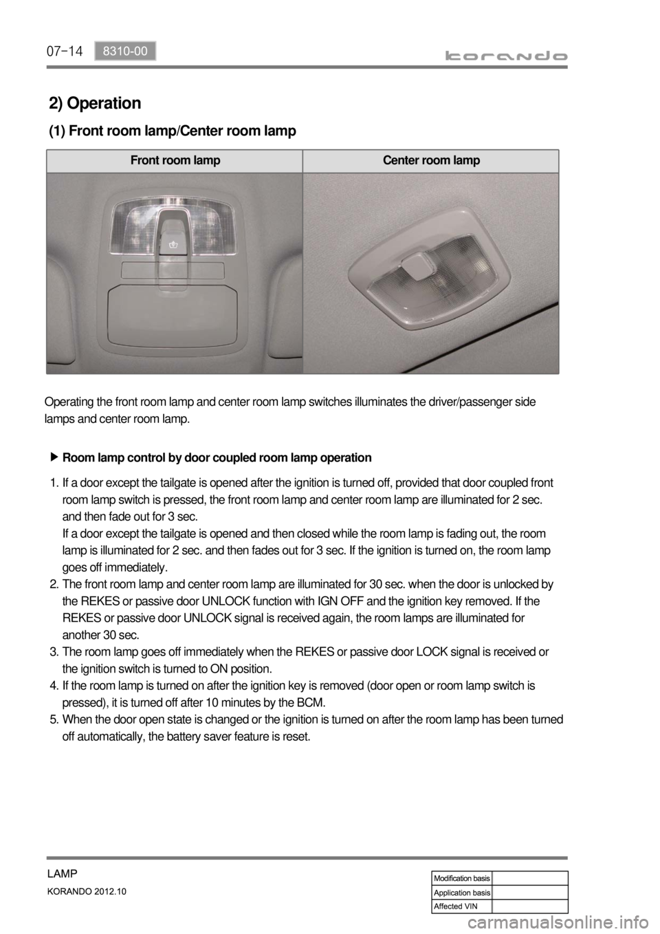
(1) Front room lamp/Center room lamp
Front room lamp Center room lamp
Operating the front room lamp and center room lamp switches illuminates the driver/passenger side
lamps and center room lamp.
Room lamp control by door coupled room lamp operation ▶
If a door except the tailgate is opened after the ignition is turned off, provided that door coupled front
room lamp switch is pressed, the front room lamp and center room lamp are illuminated for 2 sec.
and then fade out for 3 sec.
If a door except the tailgate is opened and then closed while the room lamp is fading out, the room
lamp is illuminated for 2 sec. and then fades out for 3 sec. If the ignition is turned on, the room lamp
goes off immediately.
The front room lamp and center room lamp are illuminated for 30 sec. when the door is unlocked by
the REKES or passive door UNLOCK function with IGN OFF and the ignition key removed. If the
REKES or passive door UNLOCK signal is received again, the room lamps are illuminated for
another 30 sec.
The room lamp goes off immediately when the REKES or passive door LOCK signal is received or
the ignition switch is turned to ON position.
If the room lamp is turned on after the ignition key is removed (door open or room lamp switch is
pressed), it is turned off after 10 minutes by the BCM.
When the door open state is changed or the ignition is turned on after the room lamp has been turned
off automatically, the battery saver feature is reset. 1.
2.
3.
4.
5.
Page 818 of 1082

01-8
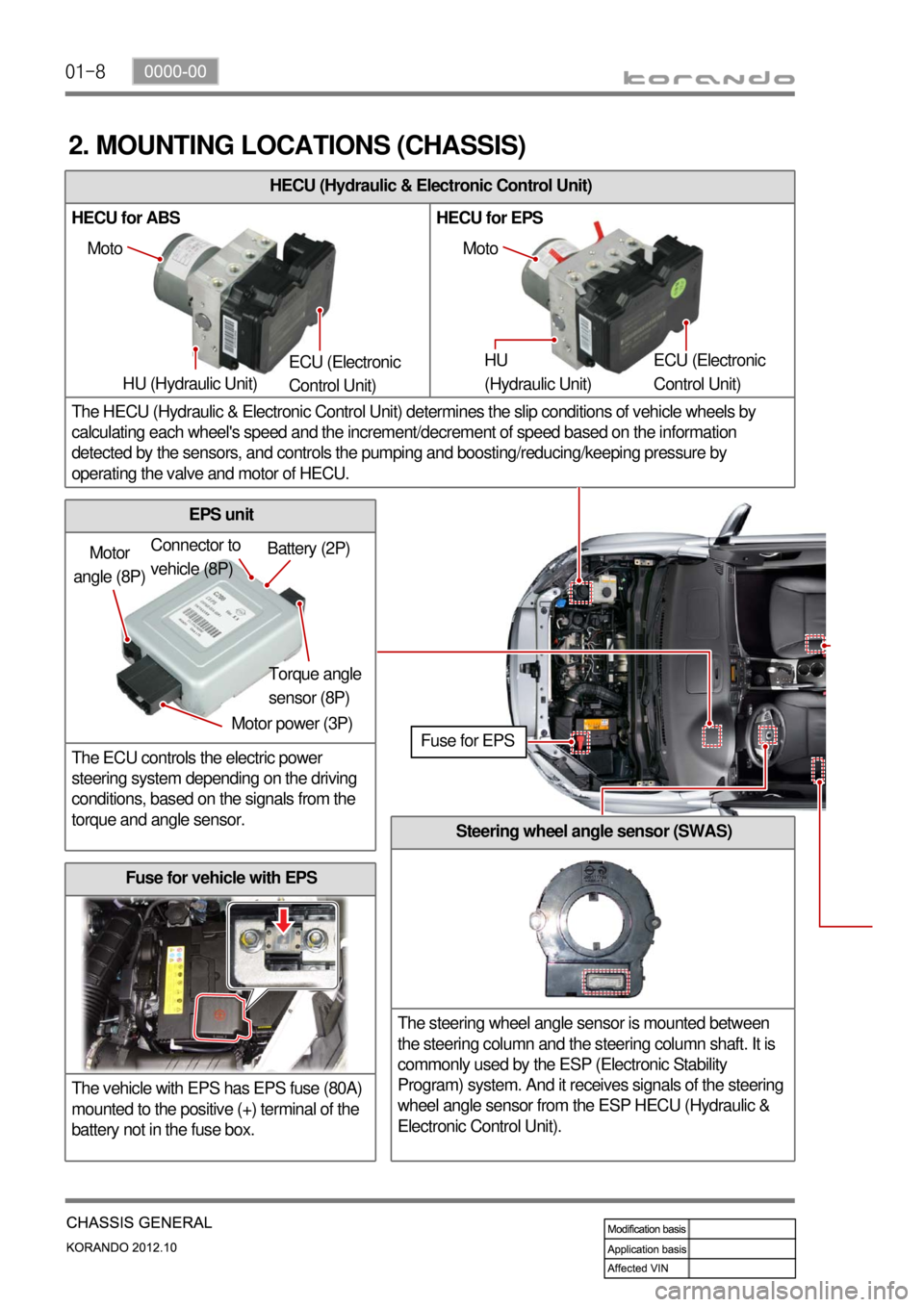
Fuse for vehicle with EPS
The vehicle with EPS has EPS fuse (80A)
mounted to the positive (+) terminal of the
battery not in the fuse box.
EPS unit
The ECU controls the electric power
steering system depending on the driving
conditions, based on the signals from the
torque and angle sensor.
HECU (Hydraulic & Electronic Control Unit)
HECU for ABS HECU for EPS
The HECU (Hydraulic & Electronic Control Unit) determines the slip conditions of vehicle wheels by
calculating each wheel's speed and the increment/decrement of speed based on the information
detected by the sensors, and controls the pumping and boosting/reducing/keeping pressure by
operating the valve and motor of HECU.
2. MOUNTING LOCATIONS (CHASSIS)
Moto
HU (Hydraulic Unit) ECU (Electronic
Control Unit) Moto
HU
(Hydraulic Unit) ECU (Electronic
Control Unit)
Motor
angle (8P)
Motor power (3P)Torque angle
sensor (8P) Battery (2P) Connector to
vehicle (8P)
Fuse for EPS
Steering wheel angle sensor (SWAS)
The steering wheel angle sensor is mounted between
the steering column and the steering column shaft. It is
commonly used by the ESP (Electronic Stability
Program) system. And it receives signals of the steering
wheel angle sensor from the ESP HECU (Hydraulic &
Electronic Control Unit).
Page 831 of 1082

01-210000-00
ECU
The ECU controls the electric
power steering system
depending on the driving
conditions, based on the
signals from the torque and
angle sensor.
2) EPS (Electric Power Steering)
Fuse
The vehicle with EPS has
EPS fuse (80A) mounted to
the positive (+) terminal of the
battery, and this fuse supplies
power to the EPS unit
directly..
Steering gear box assembly
When the driver turns the steering wheel, a torque is generated and the torque sensor and the steering
angle sensor in the EPS system detect the rotation of the steering column to run the electric motor. At
this time, the worm gear connected to the motor drives the helical gear mounted to the steering column
to generate the assist torque for the steering column. This allows the driver to operate the steering
wheel easier.
ECU
Tie rod end
Tie rod end Gear boxSteering cylinder
Steering wheel assembly
BLAC motor
Lower
shaft Column
shaft
Colum shaft assembly
The column shaft assembly consists
of BLAC motor, ECU, torque and
angle sensors. The electric power
steering (EPS) system uses the
electric motor to assist the steering
force. It functions independently
regardless of whether the engine is
running or not, unlike the existing
hydraulic power steering.
The lower shafts functions in the
same way as the hydraulic type.
Page 833 of 1082

01-230000-00
3) General Instructions
Before lifting up the vehicle with a lift, correctly support the lifting points.
When using a jack, park the vehicle on a level ground and place the wheel chocks under the tires.
Position the jack under the frame and lift up the vehicle and then support with chassis stand before
service work.
Make sure to disconnect the negative (-) cable from the battery to prevent any damage to electric
systems.
If you have to work on vehicle, cover the seats and floor with protection covers to avoid any
damage and contamination.
Brake fluid and anti-freeze can damage the painted surface of body. So carefully handle them
during service work.
To improve the efficiency of service work, use only recommended and specified tools.
Use only Ssangyong genuine spare parts.
Never reuse the cotter pin, gasket, O-ring, oil seal, lock washer and self-locking nut. Replace them
with new ones. If reused, normal functions cannot be maintained.
Store the disassembled parts as a set based on disassembly order and unit.
Pay particular attention not to miss or mix the fasteners.
If necessary, especially for inspection, clean the removed parts completely.
Apply the oil or grease on the running and sliding surfeces before installation. Use the specified
sealant and gasket to prevent leakage if necessary.
Tighten the fasteners to the specified tightening torque.
As a final stage of service work, check if the serviced system is working properly and the problem
has been eliminated clearly. (1)
(2)
(3)
(4)
(5)
(6)
(7)
(8)
(9)
(10)
(11)
(12)
(13)
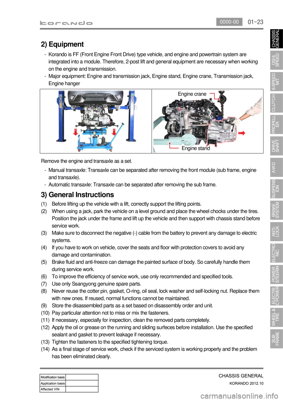
(14) Remove the engine and transaxle as a set.
Manual transaxle: Transaxle can be separated after removing the front module (sub frame, engine
and transaxle).
Automatic transaxle: Transaxle can be separated after removing the sub frame. -
-
2) Equipment
Korando is FF (Front Engine Front Drive) type vehicle, and engine and powertrain system are
integrated into a module. Therefore, 2-post lift and general equipment are necessary when working
on the engine and transmission.
Major equipment: Engine and transmission jack, Engine stand, Engine crane, Transmission jack,
Engine hanger -
-
Engine stand
Engine crane
Page 847 of 1082

02-133680-01
4. LIMP HOME MODE
When the transaxle is defective ▶
In the event of a system fault, the TCU also provides for failure mode effect control (FMEC) to maintain
maximum functional operation of the transaxle.
In the event of a total loss of control or electrical power, the basic transaxle functions (Park, Reverse,
Neutral and Drive) are retained. The 4th and reverse gear ratios with the torque converter clutch in the
unlocked state are the retained gear states the hydraulic system supports without any electrical
assistance.
The TCU communicates with other vehicle electronic control modules by the controller area network
(CAN). If a major fault develops, the transaxle may automatically operate in a "limp home" (failure)
mode to enable the vehicle to be driven to an authorized dealer for repair.
The TCU also provides for transaxle diagnostics, which meet the requirements of OBD II legislation,
monitoring all components which may effect vehicle emissions. 1.
2.
3.
4.
When the transaxle overheats ▶
Limp home mode may also be engaged if the battery charge falls below 8V.
If the transaxle overheats, the shift patterns will automatically change to enable improved transaxle
cooling.
During transaxle overheat, the instrument cluster transaxle selector position display and the over
<009b008c00940097008c00990088009b009c0099008c0047008a00960095008b0090009b00900096009500470090009a004700900095008b0090008a0088009b008c008b0047008900a00047008d00930088009a008f00900095008e0047009b008f008c00
4702c8007e004f007e00900095009b008c0099005002c90047>indicator on the instrument
cluster until normal transaxle operating temperature is reached. 1.
2.
3.
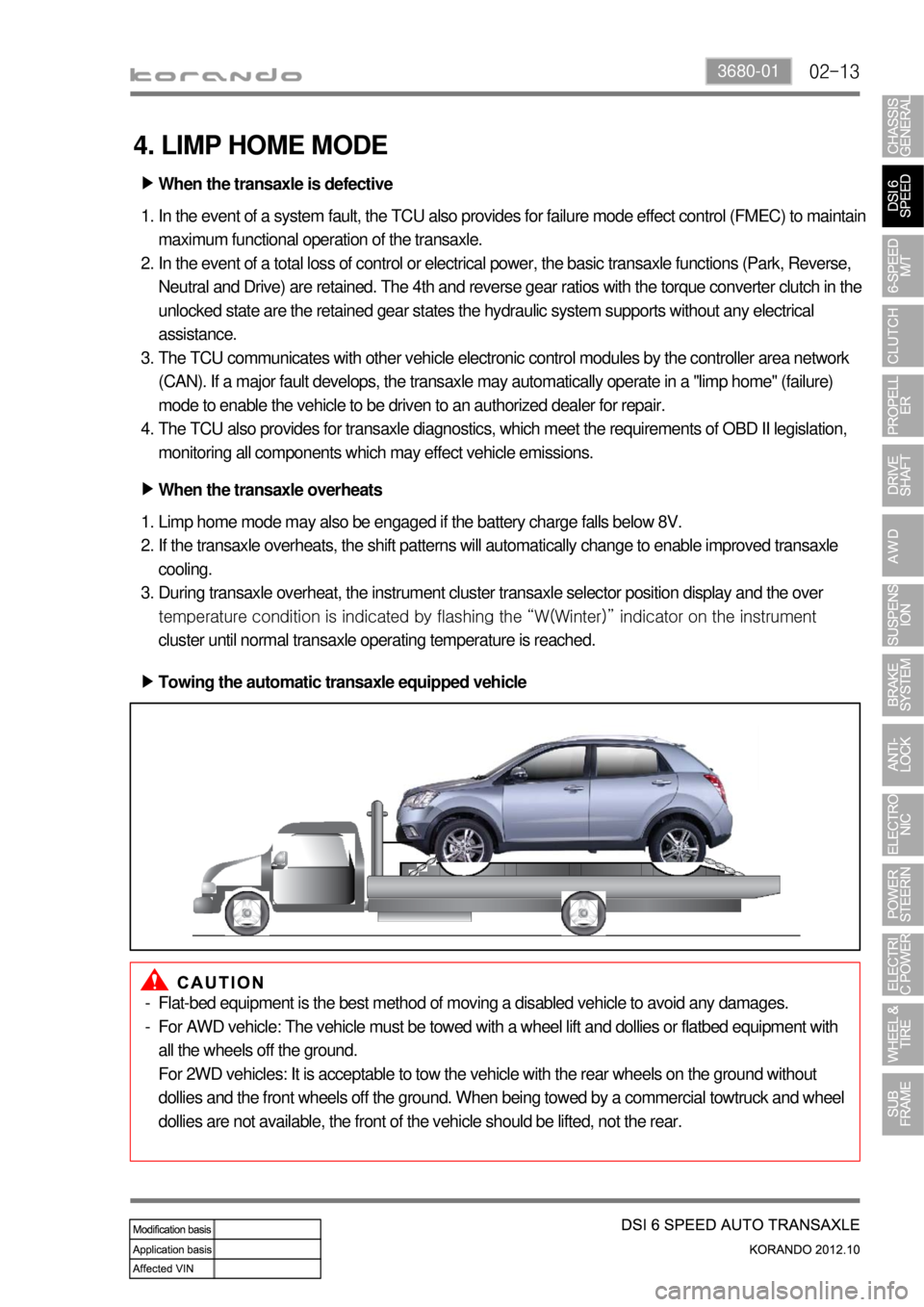
Towing the automatic transaxle equipped vehicle ▶
Flat-bed equipment is the best method of moving a disabled vehicle to avoid any damages.
For AWD vehicle: The vehicle must be towed with a wheel lift and dollies or flatbed equipment with
all the wheels off the ground.
For 2WD vehicles: It is acceptable to tow the vehicle with the rear wheels on the ground without
dollies and the front wheels off the ground. When being towed by a commercial towtruck and wheel
dollies are not available, the front of the vehicle should be lifted, not the rear. -
-
Page 956 of 1082

11-4
2) Specification of Steering Wheel Angle Sensor
Description Specification
Operating voltage 9 to 16 V
Maximum output current 10 mA
Maximum detection angle speed±100°/Sec
Operating temperature-30 to 75 ℃
Supplying voltage 9 to 16 V (battery voltage)
Output voltage (HI) approx. 3.50 V (3.0 to 4.1 V)
Output voltage (LO) approx. 1.50 V (1.3 to 2.0 V)
Pulses/rev 45 pulses/rev
3) Specification of Sensor Cluster
Description Specification
Supplying voltage approx. 12 V (8 to 16 V)
Current consumption below 250 mA -
Operating range Yaw rate sensor± 75 °/Sec
Lateral/longitudinal sensor± 14.7m/Sec²