Bearing SSANGYONG KORANDO 2012 Service Manual
[x] Cancel search | Manufacturer: SSANGYONG, Model Year: 2012, Model line: KORANDO, Model: SSANGYONG KORANDO 2012Pages: 1082, PDF Size: 96.1 MB
Page 111 of 1082
02-4
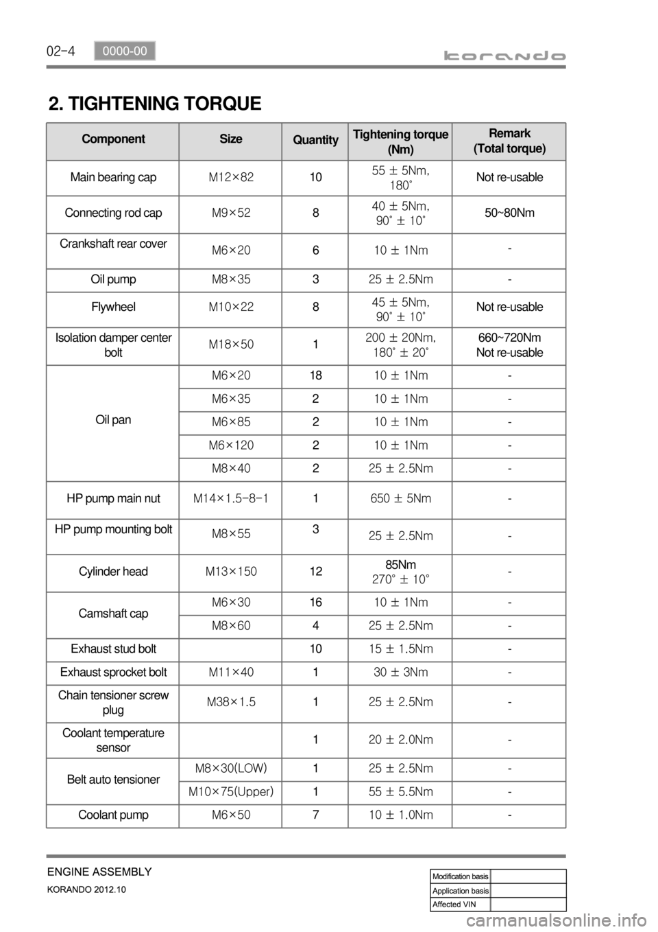
2. TIGHTENING TORQUE
Component Size
QuantityTightening torque
(Nm)Remark
(Total torque)
Main bearing capM12×821055 ± 5Nm,
180˚Not re-usable
Connecting rod capM9×52840 ± 5Nm,
90˚ ± 10˚50~80Nm
Crankshaft rear cover
M6×20610 ± 1Nm-
Oil pumpM8×35325 ± 2.5Nm-
FlywheelM10×22845 ± 5Nm,
90˚ ± 10˚Not re-usable
Isolation damper center
boltM18×501200 ± 20Nm,
180˚ ± 20˚660~720Nm
Not re-usable
Oil panM6×201810 ± 1Nm-
M6×35210 ± 1Nm-
M6×85210 ± 1Nm-
M6×120210 ± 1Nm-
M8×40225 ± 2.5Nm-
HP pump main nutM14×1.5-8-11650 ± 5Nm-
HP pump mounting bolt
M8×553
25 ± 2.5Nm-
Cylinder headM13×1501285Nm
270° ± 10°-
Camshaft capM6×301610 ± 1Nm-
M8×60425 ± 2.5Nm-
Exhaust stud bolt 1015 ± 1.5Nm-
Exhaust sprocket boltM11×40130 ± 3Nm-
Chain tensioner screw
plugM38×1.5125 ± 2.5Nm
-
Coolant temperature
sensor120 ± 2.0Nm-
Belt auto tensionerM8×30(LOW)125 ± 2.5Nm-
M10×75(Upper)155 ± 5.5Nm-
Coolant pumpM6×50710 ± 1.0Nm-
Page 136 of 1082
02-290000-00
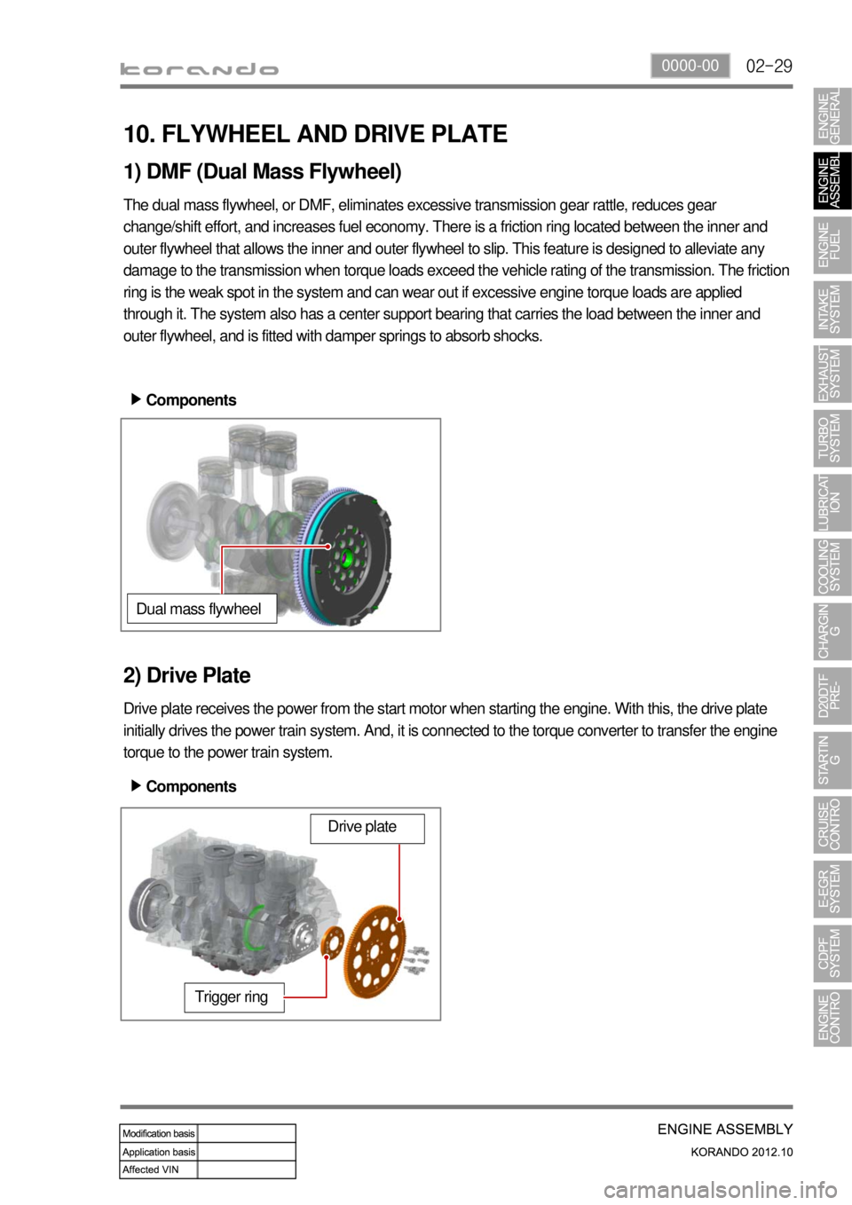
10. FLYWHEEL AND DRIVE PLATE
1) DMF (Dual Mass Flywheel)
The dual mass flywheel, or DMF, eliminates excessive transmission gear rattle, reduces gear
change/shift effort, and increases fuel economy. There is a friction ring located between the inner and
outer flywheel that allows the inner and outer flywheel to slip. This feature is designed to alleviate any
damage to the transmission when torque loads exceed the vehicle rating of the transmission. The friction
ring is the weak spot in the system and can wear out if excessive engine torque loads are applied
through it. The system also has a center support bearing that carries the load between the inner and
outer flywheel, and is fitted with damper springs to absorb shocks.
2) Drive Plate
Drive plate receives the power from the start motor when starting the engine. With this, the drive plate
initially drives the power train system. And, it is connected to the torque converter to transfer the engine
torque to the power train system.Components ▶
Dual mass flywheel
Trigger ring
Drive plate
Components ▶
Page 181 of 1082
06-4
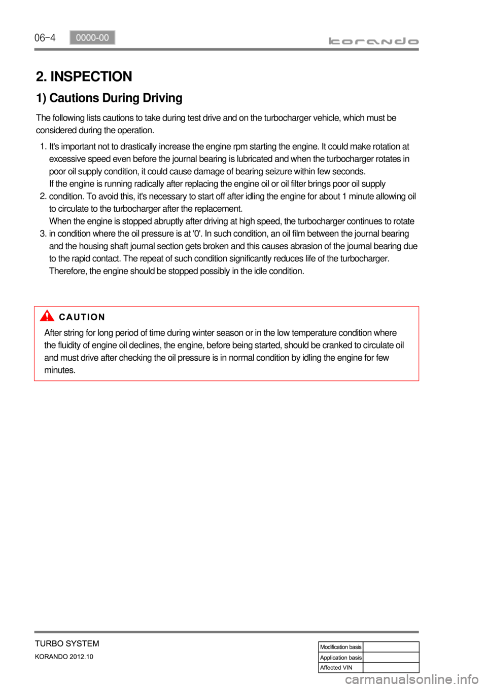
2. INSPECTION
1) Cautions During Driving
The following lists cautions to take during test drive and on the turbocharger vehicle, which must be
considered during the operation.
It's important not to drastically increase the engine rpm starting the engine. It could make rotation at
excessive speed even before the journal bearing is lubricated and when the turbocharger rotates in
poor oil supply condition, it could cause damage of bearing seizure within few seconds.
If the engine is running radically after replacing the engine oil or oil filter brings poor oil supply
condition. To avoid this, it's necessary to start off after idling the engine for about 1 minute allowing oil
to circulate to the turbocharger after the replacement.
When the engine is stopped abruptly after driving at high speed, the turbocharger continues to rotate
in condition where the oil pressure is at '0'. In such condition, an oil film between the journal bearing
and the housing shaft journal section gets broken and this causes abrasion of the journal bearing due
to the rapid contact. The repeat of such condition significantly reduces life of the turbocharger.
Therefore, the engine should be stopped possibly in the idle condition. 1.
2.
3.
After string for long period of time during winter season or in the low temperature condition where
the fluidity of engine oil declines, the engine, before being started, should be cranked to circulate oil
and must drive after checking the oil pressure is in normal condition by idling the engine for few
minutes.
Page 182 of 1082
06-50000-00
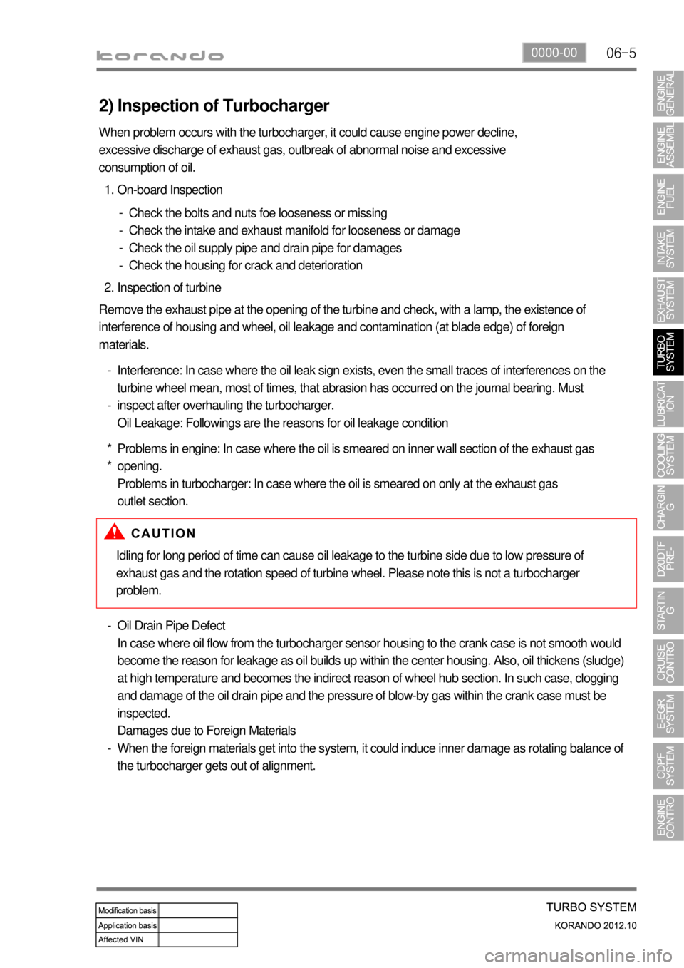
2) Inspection of Turbocharger
On-board Inspection 1.
Check the bolts and nuts foe looseness or missing
Check the intake and exhaust manifold for looseness or damage
Check the oil supply pipe and drain pipe for damages
Check the housing for crack and deterioration -
-
-
-
Inspection of turbine 2.
Remove the exhaust pipe at the opening of the turbine and check, with a lamp, the existence of
interference of housing and wheel, oil leakage and contamination (at blade edge) of foreign
materials.
Interference: In case where the oil leak sign exists, even the small traces of interferences on the
turbine wheel mean, most of times, that abrasion has occurred on the journal bearing. Must
inspect after overhauling the turbocharger.
Oil Leakage: Followings are the reasons for oil leakage condition -
-
Problems in engine: In case where the oil is smeared on inner wall section of the exhaust gas
opening.
Problems in turbocharger: In case where the oil is smeared on only at the exhaust gas
outlet section. *
* When problem occurs with the turbocharger, it could cause engine power decline,
excessive discharge of exhaust gas, outbreak of abnormal noise and excessive
consumption of oil.
Idling for long period of time can cause oil leakage to the turbine side due to low pressure of
exhaust gas and the rotation speed of turbine wheel. Please note this is not a turbocharger
problem.
Oil Drain Pipe Defect
In case where oil flow from the turbocharger sensor housing to the crank case is not smooth would
become the reason for leakage as oil builds up within the center housing. Also, oil thickens (sludge)
at high temperature and becomes the indirect reason of wheel hub section. In such case, clogging
and damage of the oil drain pipe and the pressure of blow-by gas within the crank case must be
inspected.
Damages due to Foreign Materials
When the foreign materials get into the system, it could induce inner damage as rotating balance of
the turbocharger gets out of alignment. -
-
Page 183 of 1082
06-6
3) Inspection of Turbine
Thoroughly check the followings.
Interference: In case where is trace of interference or smallest damage on the compressor wheel
means, most of times, that abrasion has occurred on the journal bearing. Must inspect after the
overhaul.
Oil Leakage: The reason for oil leakage at the compressor section is the air cleaner, clogged by
substances such as dust, causes the compressor inlet negative pressure. -
-
Rotating in high speed at no-load for extended period of time can cause oil leakage to the
compressor section as oil pressure within the center housing gets higher than pressure within the
compressor housing.
Overuse of engine break (especially in low gear) in down hill makes significantly low exhaust gas
energy compared to the time where great amount of air is required during idling conditions of the
engine. Therefore, amount of air in the compressor inlet increases but the turbocharge pressure
is not high, which makes negative pressure at the compressor section causing the oilleakage
within the center housing. a.
b.
No problem will occur with the turbocharger if above conditions are found in early stage but oil
leaked over long period of time will solidify at each section causing to breakout secondary
defects.
Damages by foreign materials: In case where the compressor wheel is damaged by foreign materials
requires having an overhaul. At this time, it's necessary to check whether the foreign materials have
contaminated intake/exhaust manifold or inside of engine.
Must absolutely not operate the turbocharger with the compressor outlet and inlet opened
as it could damage the turbocharger or be hazardous during inspection.
Page 188 of 1082
06-110000-00
3. TROUBLESHOOTING
The followings are cautions to take in handling defects of turbocharger, which must be fully aware of.
1) Cautions
After stopping the engine, check whether the bolts on pipe connecting section are
loose as well as the connecting condition of vacuum port and modulator, which is
connected to the actuator.
During idling of the engine, check for leakage in the connecting section of pipe (hoses
and pipes, duct connections, after the turbocharger) by applying soap water. The
leakage condition in the engine block and turbine housing opening can be determined
by the occurrence of abnormal noise of exhaust.
By running the engine at idle speed, abnormal vibration and noise can be checked.
Immediately stop the engine when abnormal vibration and noise is detected and make
thorough inspection whether the turbocharger shaft wheel has any damages as well as
checking the condition of connections between pipes.
In case where the noise of engine is louder than usual, there is possibility of dampness
in the areas related with air cleaner and engine or engine block and turbocharger. And
it could affect the smooth supply of engine oil and discharge.
Check for damp condition in exhaust gas when there is sign of thermal discoloration or
discharge of carbon in connecting area of the duct.
When the engine rotates or in case where there is change in noise level, check for
clogging of air cleaner or air cleaner duct or if there is any significant amount of dust in
the compressor housing.
During the inspection of center housing, inspect inside of the housing by removing the
oil drain pipe to check for sludge generation and its attachment condition at shaft area
or turbine side.
Inspect or replace the air cleaner when the compressor wheel is damaged by inflow of
foreign materials.
Inspect both side of the turbocharger wheel after removing inlet and outlet pipe of the
turbocharger.
- Is the rotation smooth when the rotor is rotated by hand?
- Is the movement of bearing normal?
- Inspect whether there has been any signs of interference between two wheels. 1.
2.
3.
4.
5.
6.
7.
8.
9.
It's important not to drive the engine when the intake manifold hose has been removed.
Page 202 of 1082
07-50000-00
1. SYSTEM DESCRIPTION
1) Overview
The lubrication system supplies oil to each lubrication section to prevent friction and wear and to remove
heat from the friction part. As the engine runs, frictional heat is generated on each lubrication section. If
this condition persists, the bearing can be burned and stuck.
In other words, it creates an oil film on each sliding surface to convert solid friction to liquid friction in
order to minimize wear and prevent temperature increasing on the friction part.
For the D20DTF engine with no oil pressure switch, the engine ECU receives the low engine oil level
signal from the oil level sensor and communicates with the instrument cluster through the CAN
communication to turn on the warning lamp.
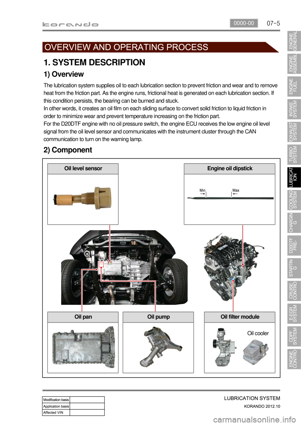
2) Component
Oil level sensorEngine oil dipstick
Oil panOil pumpOil filter module
Oil cooler
Page 349 of 1082
02-31116-01
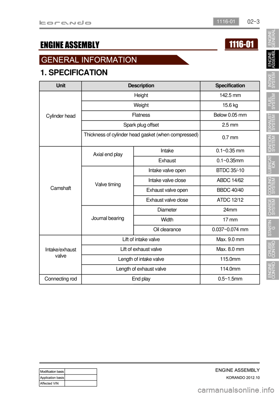
1. SPECIFICATION
Unit Description Specification
Cylinder headHeight 142.5 mm
Weight 15.6 kg
Flatness Below 0.05 mm
Spark plug offset 2.5 mm
Thickness of cylinder head gasket (when compressed)
0.7 mm
CamshaftAxial end playIntake 0.1~0.35 mm
Exhaust 0.1~0.35mm
Valve timingIntake valve open BTDC 35/-10
Intake valve close ABDC 14/62
Exhaust valve open BBDC 40/40
Exhaust valve close ATDC 12/12
Journal bearingDiameter 24mm
Width 17 mm
Oil clearance 0.037~0.074 mm
Intake/exhaust
valveLift of intake valve Max. 9.0 mm
Lift of exhaust valve Max. 8.0 mm
Length of intake valve 115.0mm
Length of exhaust valve 114.0mm
Connecting rod End play 0.5~1.5mm
Page 350 of 1082
02-4
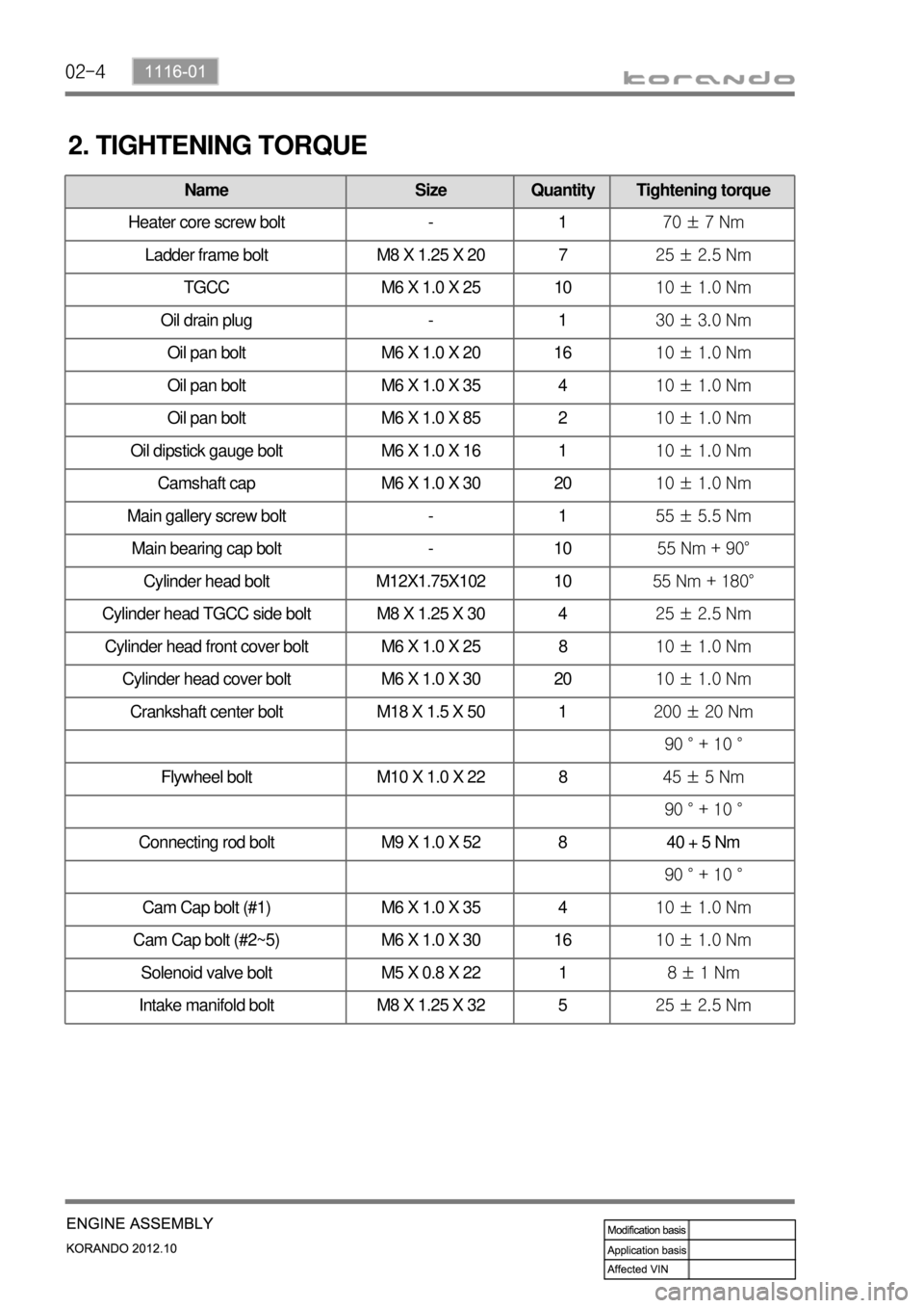
2. TIGHTENING TORQUE
Name Size Quantity Tightening torque
Heater core screw bolt - 170 ± 7 Nm
Ladder frame bolt M8 X 1.25 X 20 725 ± 2.5 Nm
TGCC M6 X 1.0 X 25 1010 ± 1.0 Nm
Oil drain plug - 130 ± 3.0 Nm
Oil pan bolt M6 X 1.0 X 20 1610 ± 1.0 Nm
Oil pan bolt M6 X 1.0 X 35 410 ± 1.0 Nm
Oil pan bolt M6 X 1.0 X 85 210 ± 1.0 Nm
Oil dipstick gauge bolt M6 X 1.0 X 16 110 ± 1.0 Nm
Camshaft cap M6 X 1.0 X 30 2010 ± 1.0 Nm
Main gallery screw bolt - 155 ± 5.5 Nm
Main bearing cap bolt - 1055 Nm + 90°
Cylinder head bolt M12X1.75X102 1055 Nm + 180°
Cylinder head TGCC side bolt M8 X 1.25 X 30 425 ± 2.5 Nm
Cylinder head front cover bolt M6 X 1.0 X 25 810 ± 1.0 Nm
Cylinder head cover bolt M6 X 1.0 X 30 2010 ± 1.0 Nm
Crankshaft center bolt M18 X 1.5 X 50 1200 ± 20 Nm
90 ° + 10 °
Flywheel bolt M10 X 1.0 X 22 845 ± 5 Nm
90 ° + 10 °
Connecting rod bolt M9 X 1.0 X 52 8 40 + 5 Nm
90 ° + 10 °
Cam Cap bolt (#1) M6 X 1.0 X 35 410 ± 1.0 Nm
Cam Cap bolt (#2~5) M6 X 1.0 X 30 1610 ± 1.0 Nm
Solenoid valve bolt M5 X 0.8 X 22 18 ± 1 Nm
Intake manifold bolt M8 X 1.25 X 32 525 ± 2.5 Nm
Page 379 of 1082
02-331130-25
Components
Overview ▶
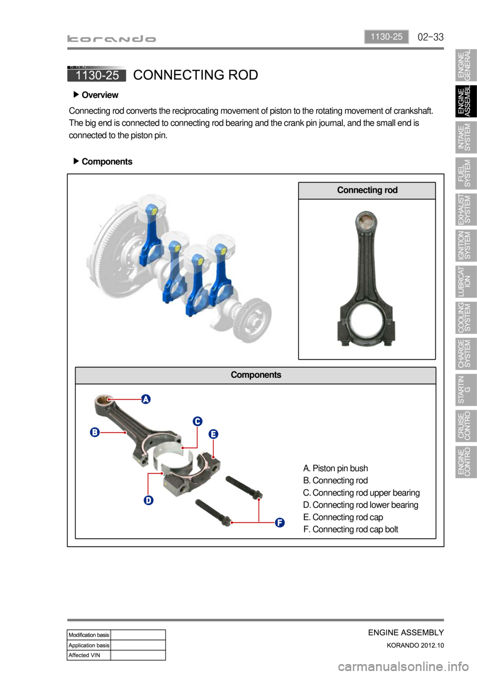
Connecting rod converts the reciprocating movement of piston to the rotating movement of crankshaft.
The big end is connected to connecting rod bearing and the crank pin journal, and the small end is
connected to the piston pin.
Components ▶
Connecting rod
Piston pin bush
Connecting rod
Connecting rod upper bearing
Connecting rod lower bearing
Connecting rod cap
Connecting rod cap bolt A.
B.
C.
D.
E.
F.