relay SSANGYONG KORANDO 2012 Service Manual
[x] Cancel search | Manufacturer: SSANGYONG, Model Year: 2012, Model line: KORANDO, Model: SSANGYONG KORANDO 2012Pages: 1082, PDF Size: 96.1 MB
Page 242 of 1082
11-6
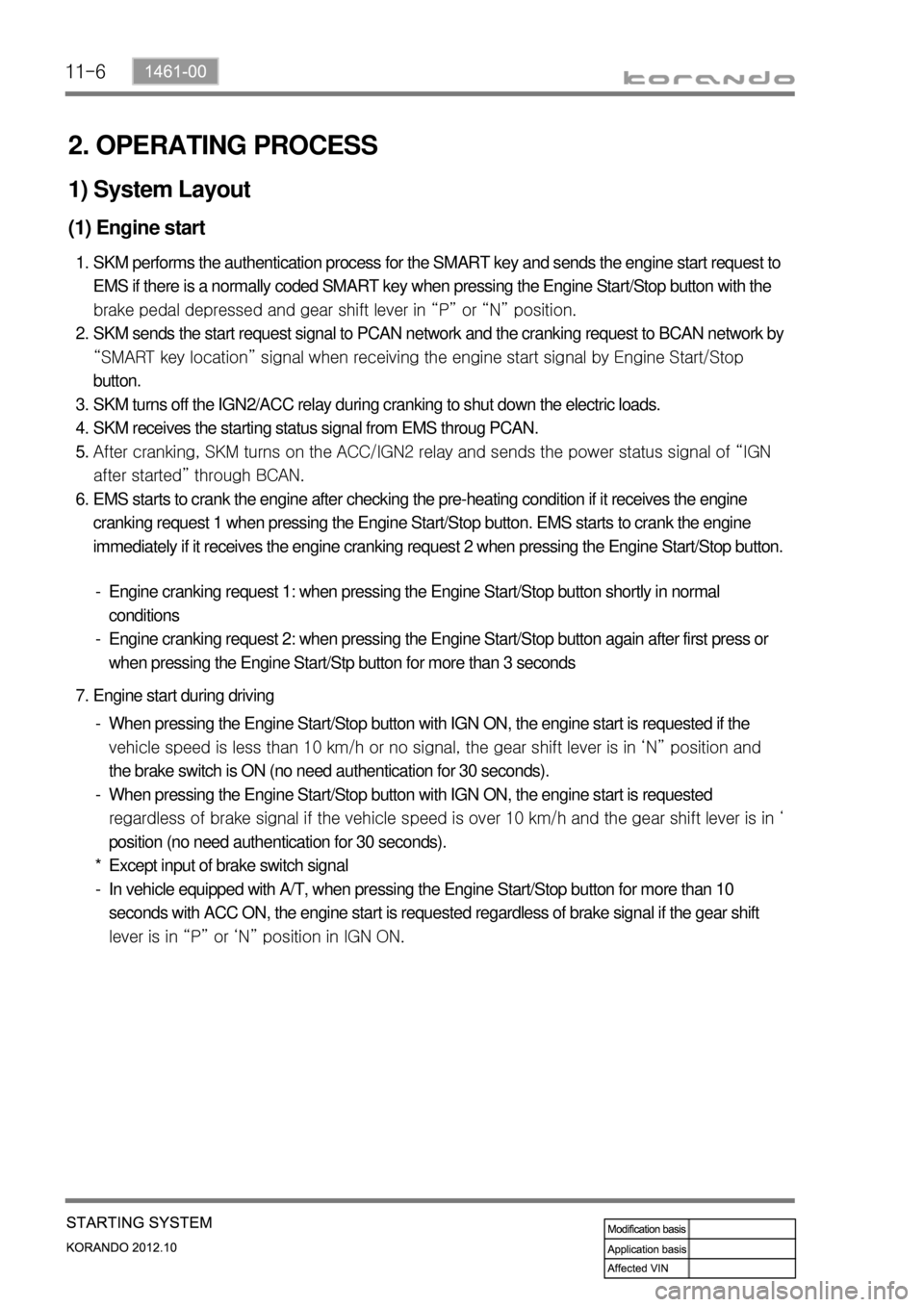
2. OPERATING PROCESS
1) System Layout
(1) Engine start
SKM performs the authentication process for the SMART key and sends the engine start request to
EMS if there is a normally coded SMART key when pressing the Engine Start/Stop button with the
<0089009900880092008c00470097008c008b008800930047008b008c00970099008c009a009a008c008b004700880095008b0047008e008c008800990047009a008f0090008d009b00470093008c009d008c0099004700900095004702c8007702c9004700
960099004702c8007502c9004700970096009a0090009b0090>on.
SKM sends the start request signal to PCAN network and the cranking request to BCAN network by
“SMART key location” signal when receiving the engine start signal by Engine Start/Stop
button.
SKM turns off the IGN2/ACC relay during cranking to shut down the electric loads.
SKM receives the starting status signal from EMS throug PCAN.
<0068008d009b008c00990047008a009900880095009200900095008e00530047007a007200740047009b009c00990095009a0047009600950047009b008f008c00470068006a006a00560070006e0075005900470099008c0093008800a000470088009500
8b0047009a008c0095008b009a0047009b008f008c00470097>ower status signal of “IGN
after started” through BCAN.
EMS starts to crank the engine after checking the pre-heating condition if it receives the engine
cranking request 1 when pressing the Engine Start/Stop button. EMS starts to crank the engine
immediately if it receives the engine cranking request 2 when pressing the Engine Start/Stop button. 1.
2.
3.
4.
5.
6.
Engine cranking request 1: when pressing the Engine Start/Stop button shortly in normal
conditions
Engine cranking request 2: when pressing the Engine Start/Stop button again after first press or
when pressing the Engine Start/Stp button for more than 3 seconds -
-
Engine start during driving 7.
When pressing the Engine Start/Stop button with IGN ON, the engine start is requested if the
<009d008c008f0090008a0093008c0047009a0097008c008c008b00470090009a00470093008c009a009a0047009b008f008800950047005800570047009200940056008f0047009600990047009500960047009a0090008e00950088009300530047009b00
8f008c0047008e008c008800990047009a008f0090008d009b> lever is in ‘N” position and
the brake switch is ON (no need authentication for 30 seconds).
When pressing the Engine Start/Stop button with IGN ON, the engine start is requested
regardless of brake signal if the vehicle s
p<008c008c008b00470090009a00470096009d008c00990047005800570047009200940056008f004700880095008b0047009b008f008c0047008e008c008800990047009a008f0090008d009b00470093008c009d008c009900470090009a00470090009500
47>‘
position (no need authentication for 30 seconds).
Except input of brake switch signal
In vehicle equipped with A/T, when pressing the Engine Start/Stop button for more than 10
seconds with ACC ON, the engine start is requested regardless of brake signal if the gear shift
lever is in “P” or ‘N” position in IGN ON. -
-
*
-
Page 284 of 1082

15-8
Engine room
relay box
E-EGR valve
Cooling fan
E-EGR cooler
bypass valveE-VGT
actuator
IMV
Throttle posi.
sensor
InjectorA/C
compressorStart motor
Variable swirl
valve
(3) Components for ECU Input
PTC heater
CAN
- Glow plug unit
- ABS & ESP unit
- BCM
- E-coupling unit
- EPS
- GCU
- Meter cluster
- SKM
- TCU
- Self diagnosis
Page 310 of 1082
15-34
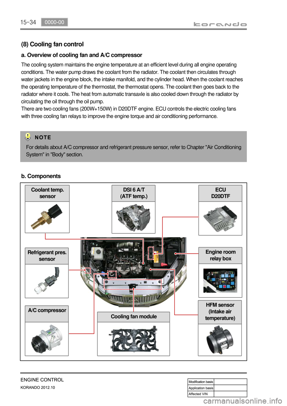
Coolant temp.
sensor
(8) Cooling fan control
a. Overview of cooling fan and A/C compressor
The cooling system maintains the engine temperature at an efficient level during all engine operating
conditions. The water pump draws the coolant from the radiator. The coolant then circulates through
water jackets in the engine block, the intake manifold, and the cylinder head. When the coolant reaches
the operating temperature of the thermostat, the thermostat opens. The coolant then goes back to the
radiator where it cools. The heat from automatic transaxle is also cooled down through the radiator by
circulating the oil through the oil pump.
There are two cooling fans (200W+150W) in D20DTF engine. ECU controls the electric cooling fans
with three cooling fan relays to improve the engine torque and air conditioning performance.
For details about A/C compressor and refrigerant pressure sensor, refer to Chapter "Air Conditioning
System" in "Body" section.
b. Components
Refrigerant pres.
sensor
A/C compressor
ECU
D20DTF DSI 6 A/T
(ATF temp.)
Cooling fan module
HFM sensor
(Intake air
temperature)
Engine room
relay box
Page 312 of 1082
15-36
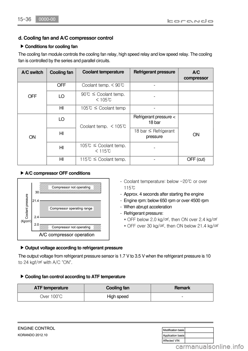
d. Cooling fan and A/C compressor control
Conditions for cooling fan ▶
The cooling fan module controls the cooling fan relay, high speed relay and low speed relay. The cooling
fan is controlled by the series and parallel circuits.
A/C switch Cooling fanCoolant temperature Refrigerant pressure
A/C
compressor
OFF OFF Coolant temp. < 90℃-
LO 90℃ ≤ Coolant temp.
< 105℃-
HI105℃ ≤ Coolant temp-
ONLO
Coolant temp. < 105℃Refrigerant pressure <
18 bar
ON HI18 bar ≤ Refrigerant
pressure
HI105℃ ≤ Coolant temp.
< 115℃-
HI115℃ ≤ Coolant temp. - OFF (cut)
A/C compressor OFF conditions ▶
Coolant temperature: below -20℃ or over
115℃
Approx. 4 seconds after starting the engine
Engine rpm: below 650 rpm or over 4500 rpm
When abrupt acceleration
Refrigerant pressure:
* OFF below 2.0 kg/㎠, then ON over 2.4 kg/㎠
* OFF over 30 kg/㎠, then ON below 21.4 kg/㎠ -
-
-
-
-
The output voltage from refrigerant pressure sensor is 1.7 V to 3.5 V when the refrigerant pressure is 10
to 24 kgf/㎠ with A/C "ON".Output voltage according to refrigerant pressure ▶
Cooling fan control according to ATF temperature ▶
ATF temperature Cooling fan Remark
Over 100˚CHigh speed -
Page 313 of 1082
15-370000-00
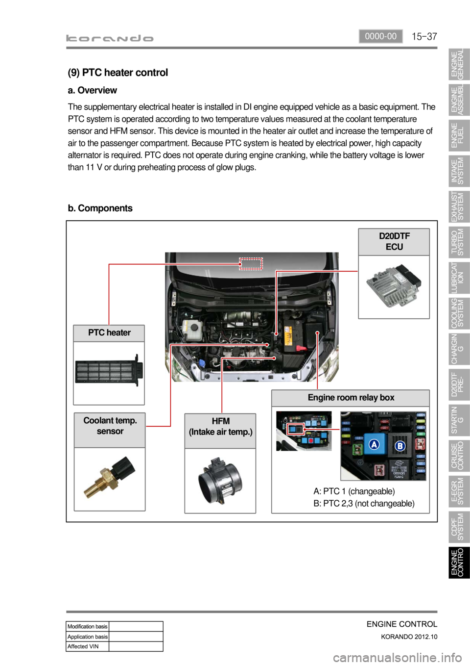
HFM
(Intake air temp.)Coolant temp.
sensor
(9) PTC heater control
a. Overview
The supplementary electrical heater is installed in DI engine equipped vehicle as a basic equipment. The
PTC system is operated according to two temperature values measured at the coolant temperature
sensor and HFM sensor. This device is mounted in the heater air outlet and increase the temperature of
air to the passenger compartment. Because PTC system is heated by electrical power, high capacity
alternator is required. PTC does not operate during engine cranking, while the battery voltage is lower
than 11 V or during preheating process of glow plugs.
b. Components
PTC heater
D20DTF
ECU
Engine room relay box
A: PTC 1 (changeable)
B: PTC 2,3 (not changeable)
Page 314 of 1082

15-38
c. Operation process
The ceramic PTC has a feature that the resistance goes up very high at a certain temperature. There
are three circuits in PTC heater. Only one circuit is connected when PTC1 relay is ON, and two circuits
are connected when PTC2 relay is ON.
<00760097008c00990088009b0090009600950047009700990096008a008c009a009a006100470099008c0088008a008f008c009a00470088009b004700880047008a008c0099009b0088009000950047009b008c00940097008c00990088009b009c009900
8c02e7008f0090008e008f00470099008c009a0090009a009b>ance→low current→less heat
<00990088008b00900088009b00900096009502e7009b008c00940097008c00990088009b009c0099008c0047008b0096009e009502e7008f0090008e008f00470099008c009a0090009a009b00880095008a008c02e7008f0090008e008f0047008a009c00
990099008c0095009b02e7009b008c00940097008c00990088>ture up
Page 325 of 1082
15-490000-00
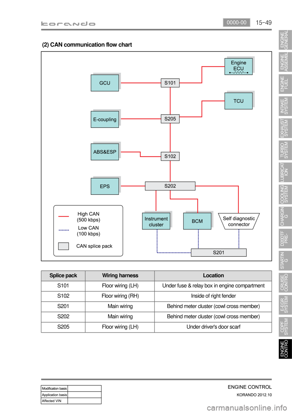
(2) CAN communication flow chart
Splice pack Wiring harness Location
S101 Floor wiring (LH) Under fuse & relay box in engine compartment
S102 Floor wiring (RH) Inside of right fender
S201 Main wiring Behind meter cluster (cowl cross member)
S202 Main wiring Behind meter cluster (cowl cross member)
S205 Floor wiring (LH) Under driver's door scarf
Page 336 of 1082

01-12
4. CODING AND SETUP
1) Engine Variant Coding
Description Coding
Vehicle speed input to ECUCAN
with ABS or ESP: CAN
WIRE
Fan3 Relays
3 Relays
PWM fan
Auto cruiseNO
with Auto cruise system: YES
YES
Engine level controlNO
without Engine level control system: NO
(Korando)
YES
G-sensorNO
with 2WD ABS and non-ABS: NO
with 4WD ABS and ESP: YES
YES
Smart keyNO
with Smart key: YES
YES
Page 483 of 1082
15-18
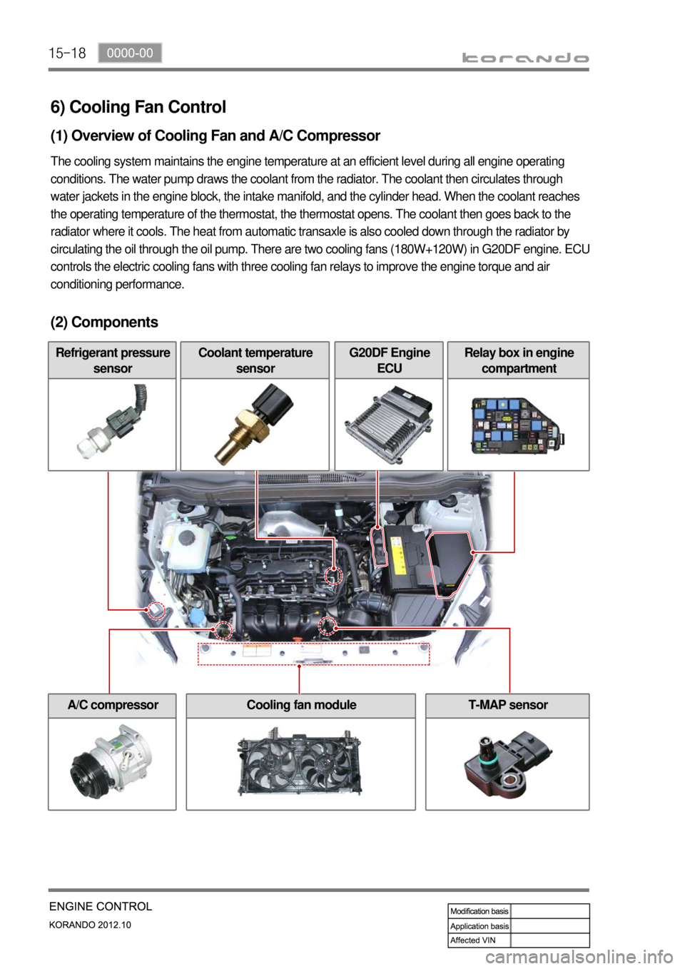
6) Cooling Fan Control
(1) Overview of Cooling Fan and A/C Compressor
The cooling system maintains the engine temperature at an efficient level during all engine operating
conditions. The water pump draws the coolant from the radiator. The coolant then circulates through
water jackets in the engine block, the intake manifold, and the cylinder head. When the coolant reaches
the operating temperature of the thermostat, the thermostat opens. The coolant then goes back to the
radiator where it cools. The heat from automatic transaxle is also cooled down through the radiator by
circulating the oil through the oil pump. There are two cooling fans (180W+120W) in G20DF engine. ECU
controls the electric cooling fans with three cooling fan relays to improve the engine torque and air
conditioning performance.
(2) Components
Refrigerant pressure
sensorCoolant temperature
sensorG20DF Engine
ECURelay box in engine
compartment
A/C compressorCooling fan moduleT-MAP sensor
Page 485 of 1082
15-20
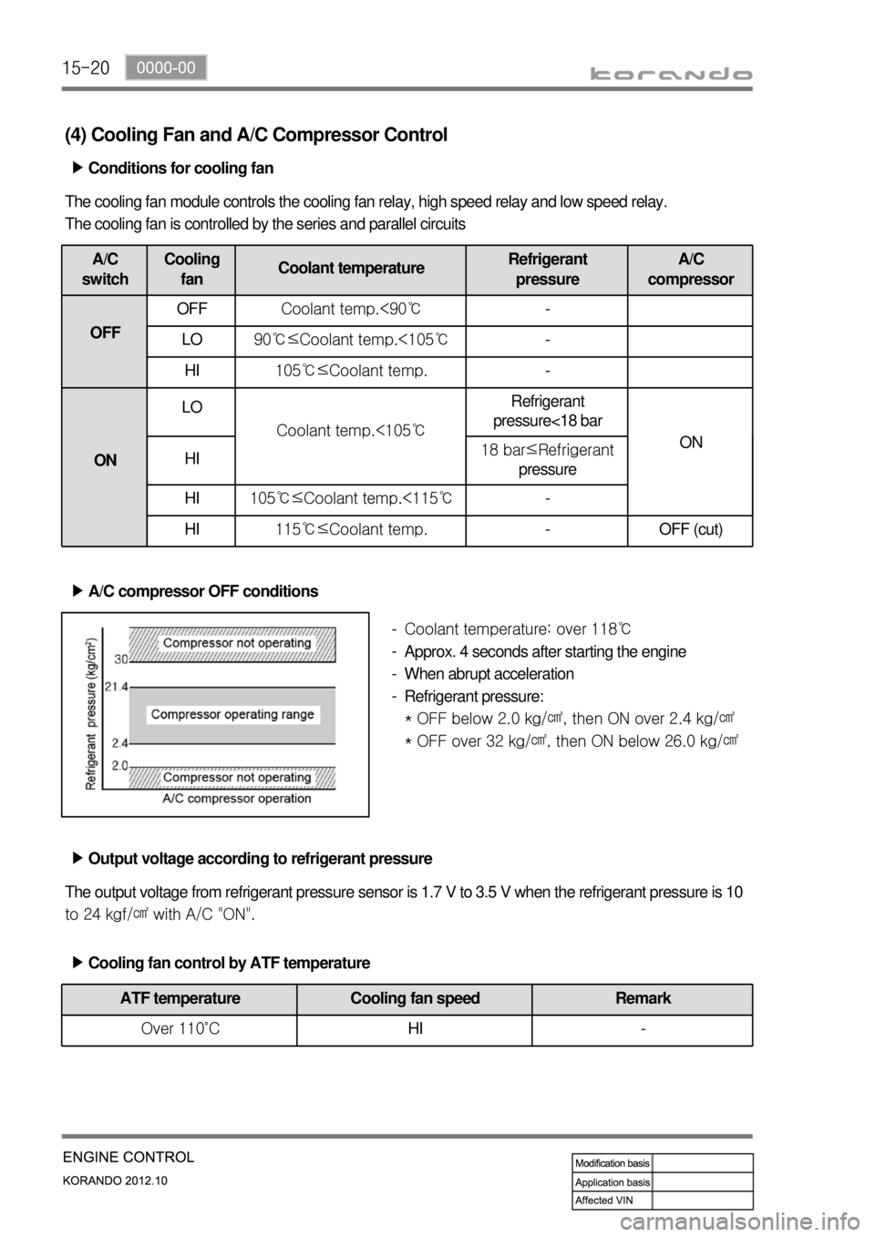
(4) Cooling Fan and A/C Compressor Control
Conditions for cooling fan ▶
The cooling fan module controls the cooling fan relay, high speed relay and low speed relay.
The cooling fan is controlled by the series and parallel circuits
A/C
switchCooling
fanCoolant temperatureRefrigerant
pressureA/C
compressor
OFFOFFCoolant temp.<90℃-
LO90℃≤Coolant temp.<105℃-
HI105℃≤Coolant temp.-
ONLO
Coolant temp.<105℃Refrigerant
pressure<18 bar
ON
HI18 bar≤Refrigerant
pressure
HI105℃≤Coolant temp.<115℃-
HI115℃≤Coolant temp.- OFF (cut)
A/C compressor OFF conditions ▶
Coolant temperature: over 118℃
Approx. 4 seconds after starting the engine
When abrupt acceleration
Refrigerant pressure:
* OFF below 2.0 kg/㎠, then ON over 2.4 kg/㎠
* OFF over 32 kg/㎠, then ON below 26.0 kg/㎠ -
-
-
-
Output voltage according to refrigerant pressure ▶
The output voltage from refrigerant pressure sensor is 1.7 V to 3.5 V when the refrigerant pressure is 10
to 24 kgf/㎠ with A/C "ON".
Cooling fan control by ATF temperature ▶
ATF temperature Cooling fan speed Remark
Over 110˚CHI -