reset SSANGYONG KORANDO 2012 Service Manual
[x] Cancel search | Manufacturer: SSANGYONG, Model Year: 2012, Model line: KORANDO, Model: SSANGYONG KORANDO 2012Pages: 1082, PDF Size: 96.1 MB
Page 260 of 1082
12-138530-00
Do not move the shift lever to Neutral position while driving with the cruise control turned on.
Otherwise, it may result in system malfunction or accidents.
Always be prepared to use the brake or accelerator pedal for safe driving while the cruise control
system is running.
The actual speed can be different from the set speed momentarily when driving on a uphill or
downhill. So, it is recommended to disable the cruise control function on a uphill or downhill. hen
driving on a steep hill use the engine brake and foot brake properly to protect the vehicle system
and for a safe driving.
Ensure that the safe distance is maintained and use the brake pedal if needed. 1.
2.
3.
4.
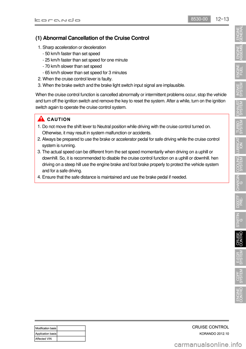
(1) Abnormal Cancellation of the Cruise Control
Sharp acceleration or deceleration
- 50 km/h faster than set speed
- 25 km/h faster than set speed for one minute
- 70 km/h slower than set speed
- 65 km/h slower than set speed for 3 minutes
When the cruise control lever is faulty.
When the brake switch and the brake light switch input signal are implausible. 1.
2.
3.
When the cruise control function is cancelled abnormally or intermittent problems occur, stop the vehicle
and turn off the ignition switch and remove the key to reset the system. After a while, turn on the ignition
switch again to operate the cruise control system.
Page 293 of 1082

15-170000-00
(3) Accelerometer Control
a. Resetting the pilot injection
The accelerometer is used to reset the pilot injection flow in closed loop for each injector. This method
allows the correction of any injector deviations over a period of time. The principle of use of the
accelerometer is based on the detection of the combustion noises.
The sensor is positioned in such a way as to receive the maximum signal for all the cylinders. The raw
signals from the accelerometer are processed to obtain a variable which quantifies the intensity of the
combustion. This variable, known as the ratio, consists of the ratio between the intensity of the
background noise and the combustion noise.
A first window is used to establish the background noise level of the accelerometer signal for each
cylinder. This window must therefore be positioned at a moment when there cannot be any
combustion.
The second window is used to measure the intensity of the pilot combustion. Its position is such that
only the combustion noises produced by the pilot injection are measured . It is therefore placed just
before the main injection. 1.
2.
The accelerometer does not allow any evaluation of the quantity injected. However, the pulse value will
be measured when the injector starts injection and this pulse value is called the MDP (Minimum Drive
Pulse). On the basis of this information, it is possible to efficiently correct the pilot flows. The pilot
injection resetting principle therefore consists of determining the MDP, in other words the pulse
corresponding to the start of the increase in value of the ratio (increase of vibration due to fuel
combustion).
Page 294 of 1082
15-18
This is done periodically under certain operating conditions. When the resetting is finished, the new
minimum pulse value replaces the value obtained during the previous resetting. The first MDP value is
provided by the C3I. Each resetting then allows the closed loop of the MDP to be updated according to
the deviation of the injector.
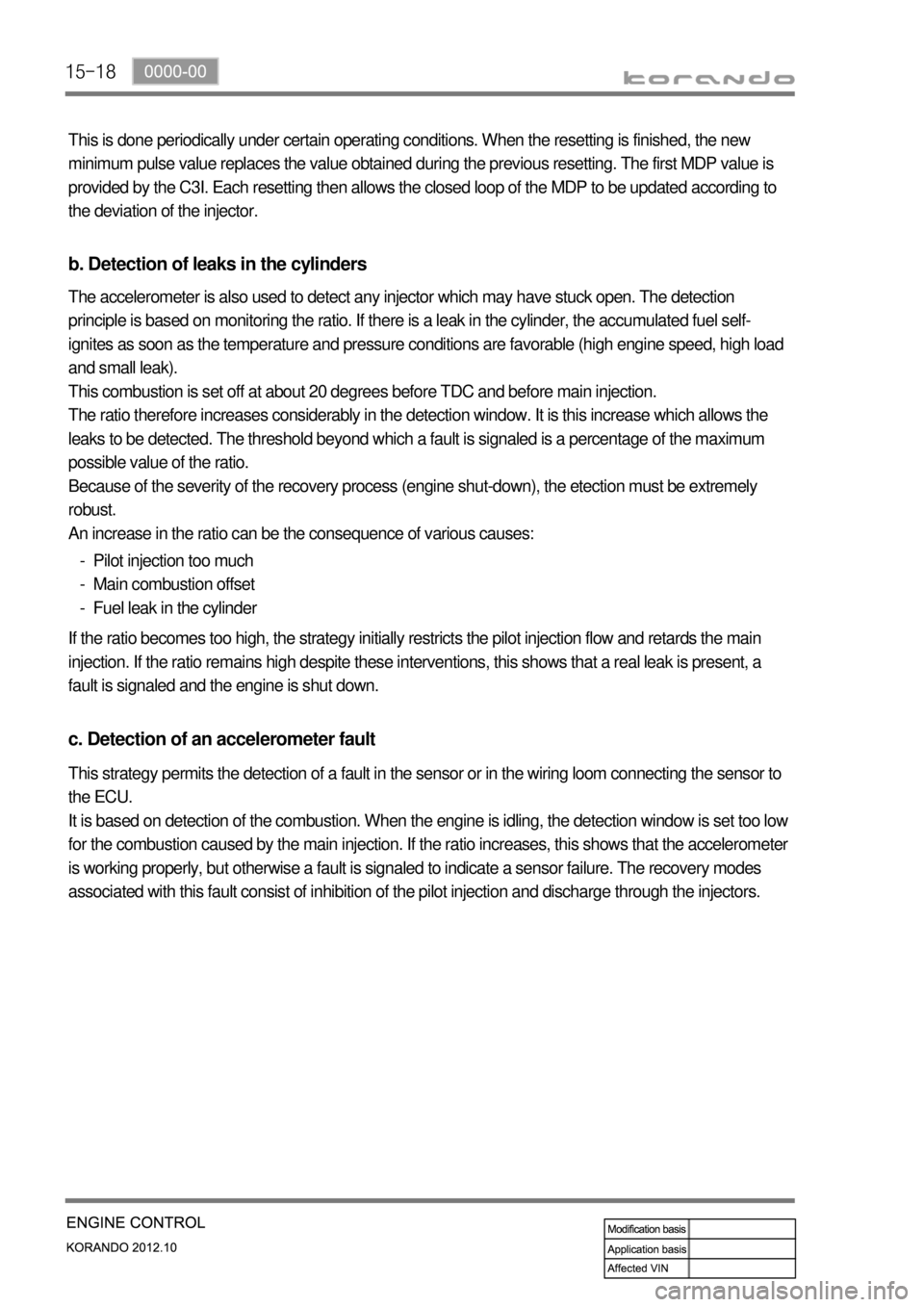
b. Detection of leaks in the cylinders
The accelerometer is also used to detect any injector which may have stuck open. The detection
principle is based on monitoring the ratio. If there is a leak in the cylinder, the accumulated fuel self-
ignites as soon as the temperature and pressure conditions are favorable (high engine speed, high load
and small leak).
This combustion is set off at about 20 degrees before TDC and before main injection.
The ratio therefore increases considerably in the detection window. It is this increase which allows the
leaks to be detected. The threshold beyond which a fault is signaled is a percentage of the maximum
possible value of the ratio.
Because of the severity of the recovery process (engine shut-down), the etection must be extremely
robust.
An increase in the ratio can be the consequence of various causes:
Pilot injection too much
Main combustion offset
Fuel leak in the cylinder -
-
-
If the ratio becomes too high, the strategy initially restricts the pilot injection flow and retards the main
injection. If the ratio remains high despite these interventions, this shows that a real leak is present, a
fault is signaled and the engine is shut down.
c. Detection of an accelerometer fault
This strategy permits the detection of a fault in the sensor or in the wiring loom connecting the sensor to
the ECU.
It is based on detection of the combustion. When the engine is idling, the detection window is set too low
for the combustion caused by the main injection. If the ratio increases, this shows that the accelerometer
is working properly, but otherwise a fault is signaled to indicate a sensor failure. The recovery modes
associated with this fault consist of inhibition of the pilot injection and discharge through the injectors.
Page 467 of 1082
12-138530-00
Do not move the shift lever to Neutral position while driving with the cruise control turned on.
Otherwise, it may result in system malfunction or accidents.
Always be prepared to use the brake or accelerator pedal for safe driving while the cruise control
system is running.
The actual speed can be different from the set speed momentarily when driving on a uphill or
downhill. So, it is recommended to disable the cruise control function on a uphill or downhill. hen
driving on a steep hill use the engine brake and foot brake properly to protect the vehicle system
and for a safe driving.
Ensure that the safe distance is maintained and use the brake pedal if needed. 1.
2.
3.
4.
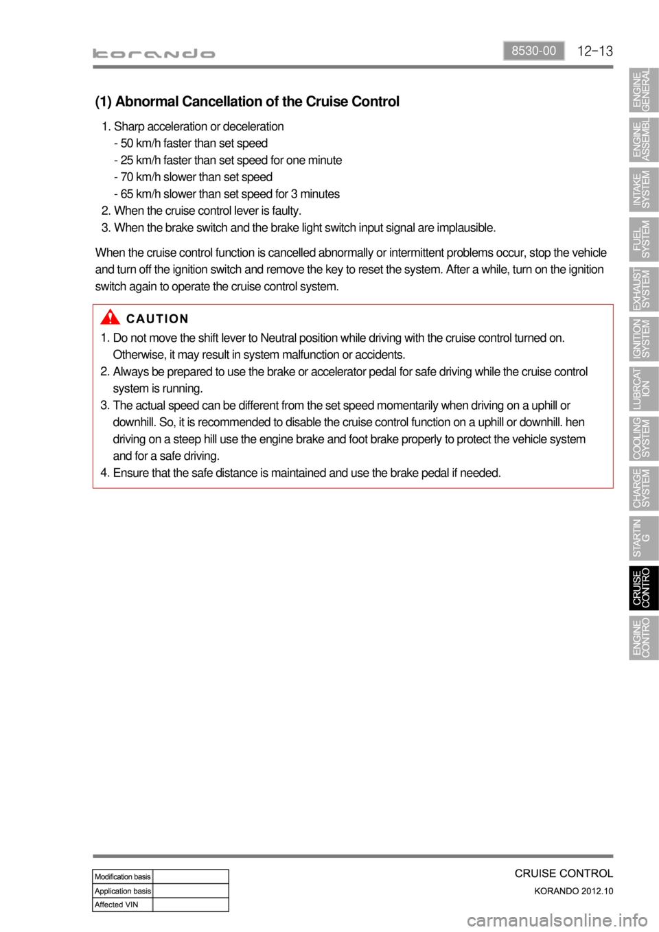
(1) Abnormal Cancellation of the Cruise Control
Sharp acceleration or deceleration
- 50 km/h faster than set speed
- 25 km/h faster than set speed for one minute
- 70 km/h slower than set speed
- 65 km/h slower than set speed for 3 minutes
When the cruise control lever is faulty.
When the brake switch and the brake light switch input signal are implausible. 1.
2.
3.
When the cruise control function is cancelled abnormally or intermittent problems occur, stop the vehicle
and turn off the ignition switch and remove the key to reset the system. After a while, turn on the ignition
switch again to operate the cruise control system.
Page 610 of 1082
03-44
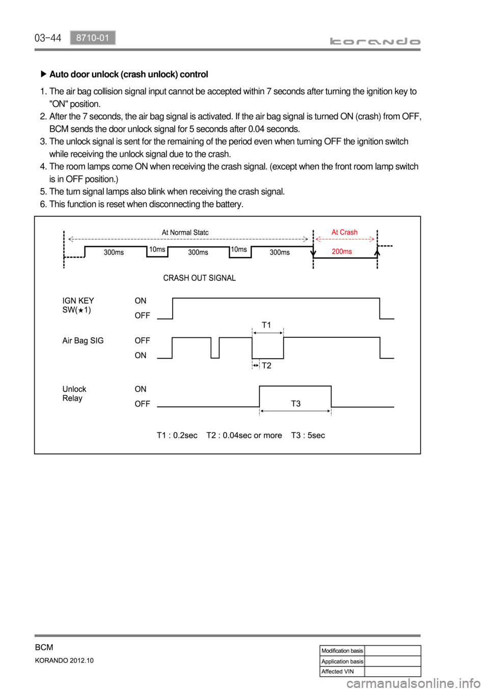
Auto door unlock (crash unlock) control ▶
The air bag collision signal input cannot be accepted within 7 seconds after turning the ignition key to
"ON" position.
After the 7 seconds, the air bag signal is activated. If the air bag signal is turned ON (crash) from OFF,
BCM sends the door unlock signal for 5 seconds after 0.04 seconds.
The unlock signal is sent for the remaining of the period even when turning OFF the ignition switch
while receiving the unlock signal due to the crash.
The room lamps come ON when receiving the crash signal. (except when the front room lamp switch
is in OFF position.)
The turn signal lamps also blink when receiving the crash signal.
This function is reset when disconnecting the battery. 1.
2.
3.
4.
5.
6.
Page 649 of 1082

04-158712-03
(5) Puddle (approach) lamp control
Operating condition ▶
When the driver approaches the vehicle in theft deterrent mode (within 1 m), the SKM sends the
puddle lamp operation signal through the BCAN if a smart key is identified.
The SKM starts to search for a smart key 30 sec. after the vehicle has entered the theft deterrent
mode. -
-
Continuous operation ▶
Reset conditions ▶
Standby mode operation ▶When a smart key is identified within 1 m from the vehicle in theft deterrent mode, the SKM sends the
puddle lamp operation signal (10 min. timer activated) through the BCAN. If a smart key is
continuously found within 10 min. the SKM sends the puddle lamp signal again for continuous
operation (up to 2 times within 10 min.)
The SKM starts to search for a smart key 30 sec. after sending the 1st puddle lamp operation signal.
If a smart key is found, the SKM sends the 2nd operation signal. -
-
10 min. timer terminated
Re-entering theft deterrent mode after deactivation -
-
Duration Function Time (s)
1st within 5 days Normal monitoring time 1.25
2nd within 5 to 14 days Increasing monitoring time 1.5
3rd 14 days or more Vehicle is stationary.
The SKM sends the signals for [AUTO approach], [REKES UNLOCK] and [Passive UNLOCK] through
the BCAN to control the puddle (approach) lamp by AUTO puddle (approach) lamp ON, REKES
UNLOCK and Passive entry UNLOCK.
Default setting is AUTO approach.
The AUTO approach function can be turned ON or OFF using a diagnostic device.AUTO puddle (approach) lamp ON ▶
REKES or Passive door LOCK/UNLOCKStop/Standby operation reset condition: ▶
The SKM sends the signals for [REKES UNLOCK] and [Passive UNLOCK] to control the puddle
(approach) lamp ON function by REKES UNLOCK and Passive entry UNLOCK in theft deterrent mode. Puddle (approach) lamp ON by REKES UNLOCK & Puddle (approach) lamp ON by Passive
entry UNLOCK ▶
Page 653 of 1082

04-198712-03
4) Smart Key Verification Time Control
(1) Pre-verification timer
When the operation signal from the START switch is received, the START & power control functions can
be performed without smart key verification.
(2) Immobilizer verification timer
The immobilizer verification status indicates that it is possible to respond to the request message sent
from the EMS to deactivate the immobilizer. The SKM verified a smart key and the engine can be
started.
The 30-second immobilizer verification time is started when:
the ignition status is changed to IGN by the START switch while the pre-verification timer is activated.
the ignition status is changed to IGN by the smart key verification while the pre-verification timer is
stopped; the SKM verified a smart key by the brake switch signal while the immobilizer verification
timer is stopped or the ignition status is IGN ON.
the SKM verified a smart key successfully if the immobilizer verification timer is stopped with IGN
ON/immobilizer verification /brake switch ON. -
-
-
Condition SKM operation
- when door closed signal is input with - B+ or ACC ON
- when brake is applied with - B+ or ACC ON
- when START switch is operated with - B+
- when smart key is inserted into slot & brake switch is
operated or START switch is operated with - B+Once the vehicle interior verification
is completed, 30 sec. pre-verification
timer is started
when the ignition is turned OFF with IGN ON and engine
running 30 sec. pre-verification timer is
started without re-verification
Timer deactivation conditions: after 30 sec. has passed, IGN ON, Outside door handle switch ON,
entering theft deterrent mode when door condition is changed
IGN1 OFF
30 sec. has passed after immobilizer verification
Any door is opened and then closed when all doors are closed & smart key out
When the engine starts to run, the immobilizer verification status is determined, and the immobilizer will
not be deactivated until the ignition status is changed to IGN/ACC/OFF.
The immobilizer is not deactivated when the key out warning condition is met while the engine is
running. (when the RND is received by the EMS reset while the engine is running)
When attempting to start the engine without immobilizer verification, the system performs smart key
verification procedures, and sends the engine start request to EMS only when the verification result is
normal. -
-
-
*
*
*Entry conditions ▶
Deactivation condition ▶
Page 660 of 1082

04-26
7) START Switch Control
Status Turning on conditions
OFF IGN OFF, IGN ON & engine ON
Green Engine can be started by START switch operation/Engine is cranking (IGN OFF &
brake switch ON, ACC ON & brake switch ON, IGN ON & brake switch ON, etc.)
Yellow ACC ON
Red IGN ON & engine OFF or error
Ignition status indicator on START switch ▶
(1) START switch indicator
START switch indicator output ▶
* When an error occurs, the indicator is illuminated for 0.5 sec. and goes off for 0.5 sec., and
then flashes for 10 sec.
* When all the doors are closed with B+, the LED does not flash.
Start switch indicator control ▶
Door coupled function -
1. When the driver's door is opened, the switch indicator comes on (the indicator remains on
while the door is open).
2. The indicator goes off immediately when the interior lamps are turned off.
3. The indicator goes off after the driver's door is closed and 10 sec. ON timer is activated.
4. The indicator is reset when the driver's door is opened.
Tail lamp coupled function -
Ignition
statusPower OFF
ACC ON IGN ON
(STOP)IGN ON
START ErrorRemark
Door
CloseDoor
Open
Indica-
tion
Indicator
statusOFF OFF Orange Red OFF Green Red
OFF OFF ON ON OFF ON Flashing
Illumina-
tionOFF TIME
Controlled by SKMLED
Engine START/STOP
Page 665 of 1082
04-318712-03
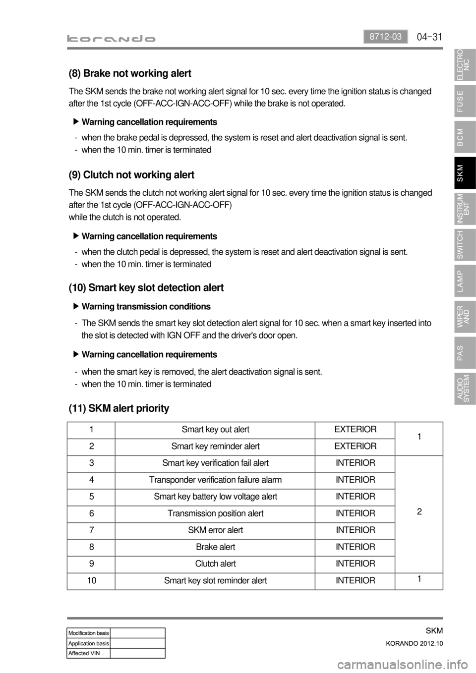
(8) Brake not working alert
The SKM sends the brake not working alert signal for 10 sec. every time the ignition status is changed
after the 1st cycle (OFF-ACC-IGN-ACC-OFF) while the brake is not operated.
when the brake pedal is depressed, the system is reset and alert deactivation signal is sent.
when the 10 min. timer is terminated -
-
(9) Clutch not working alert
The SKM sends the clutch not working alert signal for 10 sec. every time the ignition status is changed
after the 1st cycle (OFF-ACC-IGN-ACC-OFF)
while the clutch is not operated.
when the clutch pedal is depressed, the system is reset and alert deactivation signal is sent.
when the 10 min. timer is terminated -
-
(10) Smart key slot detection alert
The SKM sends the smart key slot detection alert signal for 10 sec. when a smart key inserted into
the slot is detected with IGN OFF and the driver's door open. -
(11) SKM alert priority
1 Smart key out alert EXTERIOR
1
2 Smart key reminder alert EXTERIOR
3 Smart key verification fail alert INTERIOR
2 4 Transponder verification failure alarm INTERIOR
5 Smart key battery low voltage alert INTERIOR
6 Transmission position alert INTERIOR
7 SKM error alert INTERIOR
8 Brake alert INTERIOR
9 Clutch alert INTERIOR
10 Smart key slot reminder alert INTERIOR1
Warning cancellation requirements ▶
Warning cancellation requirements ▶
Warning transmission conditions ▶
Warning cancellation requirements ▶
when the smart key is removed, the alert deactivation signal is sent.
when the 10 min. timer is terminated -
-
Page 669 of 1082

05-6
SVC class
Previous Current
Changed from figure type to bar graph type.
6) Average fuel economy reset and calibrated automatically when
refilling
7) Instant fuel consumption display changed
8) Pre-warning indicator for engine overheat removed
Both SVC and STD class
Previous Current
Reset by user Reset by user and automatic reset when refilling
9) TDMS logic changed
SVC class
Current
TDMS (Tier Direction Management System) is not displayed when EPS warning lamp comes on.
SVC class STD class
Pre-warning indicator for engine overheat is removed.
EPS warning lampTDMS displayLCD not displayed
EPS warning lamp
comes onLCD screen is not
displayed.