SSANGYONG KORANDO 2013 Service Manual
KORANDO 2013
SSANGYONG
SSANGYONG
https://www.carmanualsonline.info/img/67/57503/w960_57503-0.png
SSANGYONG KORANDO 2013 Service Manual
Trending: driver seat adjustment, engine overheat, remove seats, oil, headlamp, cruise control, pairing phone
Page 1031 of 1336
3660-01
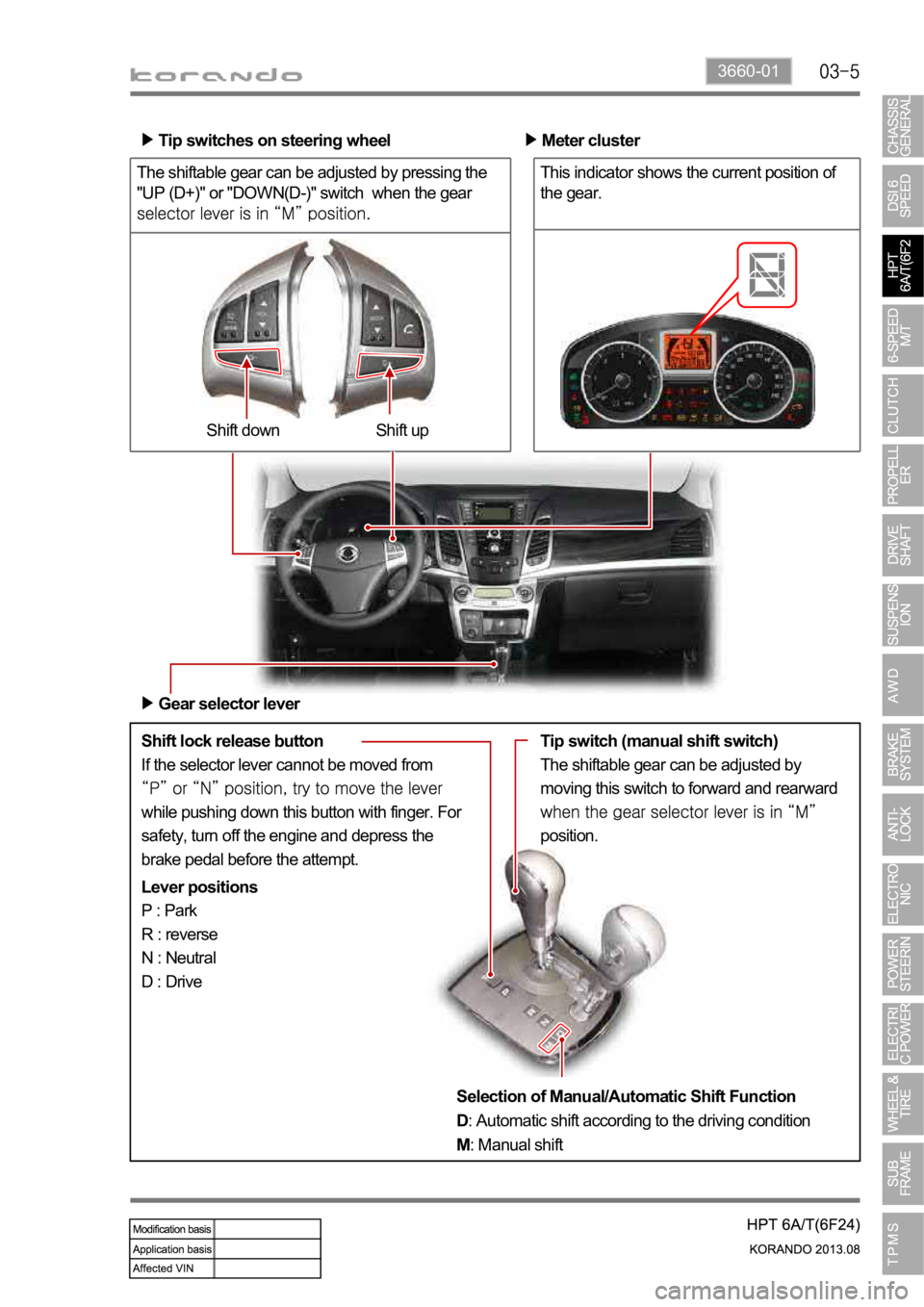
The shiftable gear can be adjusted by pressing the
"UP (D+)" or "DOWN(D-)" switch when the gear
Shift lock release button
If the selector lever cannot be moved from
while pushing down this button with finger. For
safety, turn off the engine and depress the
brake pedal before the attempt.Shift up Shift down Tip switches on steering wheel
Meter cluster
This indicator shows the current position of
the gear.
Gear selector lever
Lever positions
P : Park
R : reverse
N : Neutral
D : DriveTip switch (manual shift switch)
The shiftable gear can be adjusted by
moving this switch to forward and rearward
position.
Selection of Manual/Automatic Shift Function
D: Automatic shift according to the driving condition
M: Manual shift
Page 1032 of 1336
3. SPECIFICATIONS
1) Specifications
Type/Weight 6F24 6-speed automatic transaxle /
approx. 86 kg (including ATF)
TORQUE 230 Nm
Overall length / Center length 373.1 mm / 204 mm
Descriptions Specification
Gear ratio 1st gear 4.212
2nd gear 2.637
3rd gear 1.800
4th gear 1.386
5th gear 1.000
6th gear 0.772
Reverse gear 3.385
Shift pattern Variable
Shift range 4 Range (P-R-N-D) + Manual mode
Shift range valve VFS : 6EA
Planetary gear 3EA (Front, Middle, Rear)
Clutch 2EA
Brake 3EA
O.W.C 1EA
Oil Type ATF SP-IV M
Capacity approx. 7.1 L
Change interval Maintenance free. However, under the severe
conditions or commercially used, change the oil at
every 100,000 km (EU: 90,000 km).
Resistance of oil
temperature sensor-20
0
20
100
Weight 2WD 87.5kg
4WD 88.5kg
Page 1033 of 1336
3660-01
4. COMPONENTS
HPT 6A/T (6F24)
One-way clutchTorque converter
(with slip lockup)
Oil pumpHarness
Valve bodySide gearDriven gear
Page 1034 of 1336

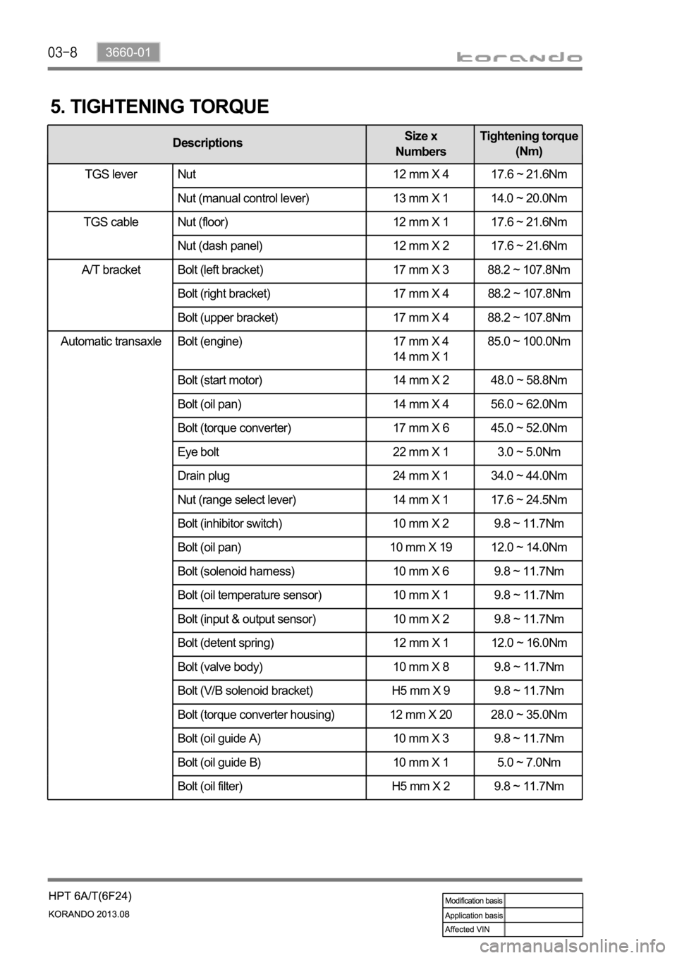
Automatic transaxle Bolt (engine) 17 mm X 4
14 mm X 1 85.0 ~ 100.0Nm
Bolt (start motor) 14 mm X 2 48.0 ~ 58.8Nm
Bolt (oil pan) 14 mm X 4 56.0 ~ 62.0Nm
Bolt (torque converter) 17 mm X 6 45.0 ~ 52.0Nm
Eye bolt 22 mm X 1 3.0 ~ 5.0Nm
Drain plug 24 mm X 1 34.0 ~ 44.0Nm
Nut (range select lever) 14 mm X 1 17.6 ~ 24.5Nm
Bolt (inhibitor switch) 10 mm X 2 9.8 ~ 11.7Nm
Bolt (oil pan) 10 mm X 19 12.0 ~ 14.0Nm
Bolt (solenoid harness) 10 mm X 6 9.8 ~ 11.7Nm
Bolt (oil temperature sensor) 10 mm X 1 9.8 ~ 11.7Nm
Bolt (input & output sensor) 10 mm X 2 9.8 ~ 11.7Nm
Bolt (detent spring) 12 mm X 1 12.0 ~ 16.0Nm
Bolt (valve body) 10 mm X 8 9.8 ~ 11.7Nm
Bolt (V/B solenoid bracket) H5 mm X 9 9.8 ~ 11.7Nm
Bolt (torque converter housing) 12 mm X 20 28.0 ~ 35.0Nm
Bolt (oil guide A) 10 mm X 3 9.8 ~ 11.7Nm
Bolt (oil guide B) 10 mm X 1 5.0 ~ 7.0Nm
Bolt (oil filter) H5 mm X 2 9.8 ~ 11.7Nm
5. TIGHTENING TORQUE
DescriptionsSize x
NumbersTightening torque
(Nm)
TGS lever Nut 12 mm X 4 17.6 ~ 21.6Nm
Nut (manual control lever) 13 mm X 1 14.0 ~ 20.0Nm
Nut (floor) 12 mm X 1 17.6 ~ 21.6Nm
Nut (dash panel) 12 mm X 2 17.6 ~ 21.6Nm
A/T bracket Bolt (left bracket) 17 mm X 3 88.2 ~ 107.8Nm
Bolt (right bracket) 17 mm X 4 88.2 ~ 107.8Nm
Bolt (upper bracket) 17 mm X 4 88.2 ~ 107.8Nm
TGS lever
TGS cable
Page 1035 of 1336
3660-01
DescriptionsSize x
NumbersTightening torque
(Nm)
Automatic
transaxleBolt (oil lubrication pipe) 10 mm X 1 9.8 ~ 11.7Nm
Bolt (oil pump) 12 mm X 7 20.0 ~ 26.0Nm
Bolt (parking rod guide) 10 mm X 2 9.8 ~ 11.7Nm
Bolt (U/D brake retainer) T40 X 6 31.0 ~ 36.0Nm
Bolt (U/D brake chamber) T30 X 2 4.9 ~ 9.8Nm
Bolt (rear cover) 12 mm X 13 28.0 ~ 35.0Nm
Page 1036 of 1336
6. SPECIAL SERVICE TOLLS
Part number Name Tool How to use
00104-001(UD) Remover &
Installer - U/D
brake return sprin
00104-002(OD) Remover&
Installer - O/D
clutch return
spring
00104-003(LR)
(use with 00104-001)Remover&
Installer - L/R
brake return
spring
* Special service tool Supplier: Tool & Tech
Page 1037 of 1336

3660-01
1. OVERVIEW
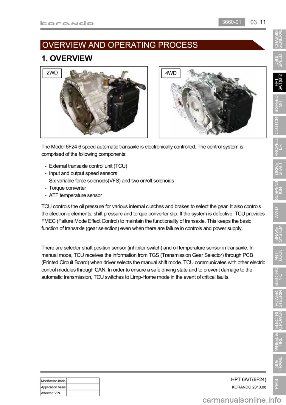
2WD4WD
The Model 6F24 6 speed automatic transaxle is electronically controlled. The control system is
comprised of the following components:
External transaxle control unit (TCU)
Input and output speed sensors
Six variable force solenoids(VFS) and two on/off solenoids
Torque converter
ATF temperature sensor -
-
-
-
-
TCU controls the oil pressure for various internal clutches and brakes to select the gear. It also controls
the electronic elements, shift pressure and torque converter slip. If the system is defective, TCU provides
FMEC (Failure Mode Effect Control) to maintain the functionality of transaxle. This keeps the basic
function of transaxle (gear selection) even when there are failure in controls and power supply.
There are selector shaft position sensor (inhibitor switch) and oil temperature sensor in transaxle. In
manual mode, TCU receives the information from TGS (Transmission Gear Selector) through PCB
(Printed Circuit Board) when driver selects the manual shift mode. TCU communicates with other electric
control modules through CAN. In order to ensure a safe driving state and to prevent damage to the
automatic transmission, TCU switches to Limp-Home mode in the event of critical faults.
Page 1038 of 1336

2. FEATURES
1) Advantages
Early Downshift with Hard Braking and Skip Shifts
When heavy braking is detected, the transaxle downshifts early and skips gears to provide increased
engine braking to provide gear selection for tip-in.
Gear Hold going Uphill/Downhill
If the accelerator pedal is released when traveling uphill, upshifts are prevented to reduce busyness on
grades. If the accelerator pedal is released when traveling downhill, upshifts are prevented to enhance
engine braking.
Drive and Reverse Engagement
A soft engagement feature avoids harsh take up of drive when selecting Drive or Reverse. This is
achieved by limiting engine speed and engine torque which results in a rapid, but progressive
engagement of either Drive or Reverse when moving from the Park or Neutral positions. Drive and
Reverse engagements from either Park or Neutral are performed in less than 2.2 seconds. There is no
drive engagement prevention strategy implemented on the transaxle system as there is sufficient engine
strategy to protect the system. However, reverse engagement is prevented until vehicle speed is less
than 7 km/h.
Page 1039 of 1336
3660-01
2) Transaxle Cooling
The transaxle cooling system ensures rapid warm-up and constant operating temperature resulting in
reduced fuel consumption and refined shift quality.
It also includes a cooler by-pass within the hydraulic system to allow sufficient lubrication to the transaxle
drivetrain in the event of a blockage in the transaxle cooler.
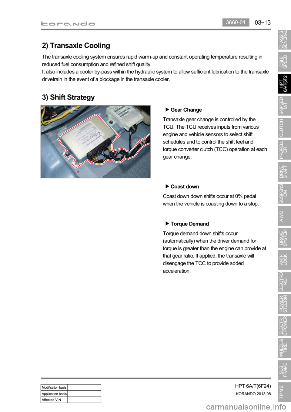
3) Shift Strategy
Gear Change
Transaxle gear change is controlled by the
TCU. The TCU receives inputs from various
engine and vehicle sensors to select shift
schedules and to control the shift feel and
torque converter clutch (TCC) operation at each
gear change.
Coast down
Coast down down shifts occur at 0% pedal
when the vehicle is coasting down to a stop.
Torque Demand
Torque demand down shifts occur
(automatically) when the driver demand for
torque is greater than the engine can provide at
that gear ratio. If applied, the transaxle will
disengage the TCC to provide added
acceleration.
Page 1040 of 1336
3. MODES AND FUNCTIONS
This allows the driver to define the highest
position. When the lever is first moved to the
one lower gear than current gear.
When driving on a slippery road, push the tip switch forward into the "+" position in "M" position.
This causes the transaxle to shift into the 2nd gear which is better for smooth driving on a slippery
road.
Trending: fuel filter, brakes, glove box, stop start, turn signal, fuel cap release, maintenance schedule


