SSANGYONG KORANDO 2013 Service Manual
KORANDO 2013
SSANGYONG
SSANGYONG
https://www.carmanualsonline.info/img/67/57503/w960_57503-0.png
SSANGYONG KORANDO 2013 Service Manual
Page 1112 of 1336
3) Basic ABS Control
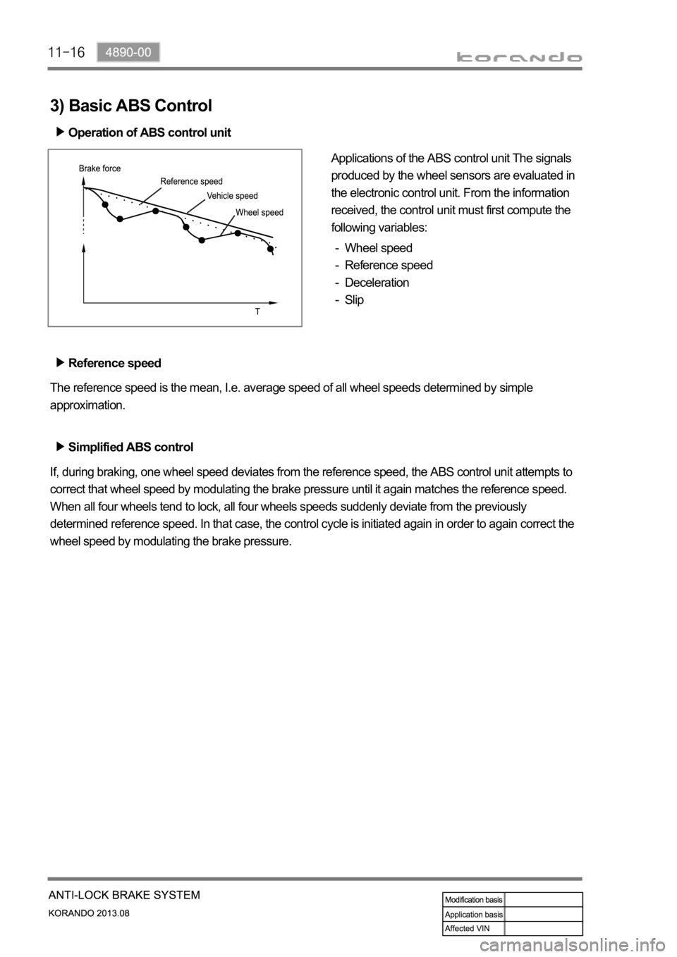
Operation of ABS control unit
Applications of the ABS control unit The signals
produced by the wheel sensors are evaluated in
the electronic control unit. From the information
received, the control unit must first compute the
following variables:
Wheel speed
Reference speed
Deceleration
Slip -
-
-
-
Reference speed
The reference speed is the mean, I.e. average speed of all wheel speeds determined by simple
approximation.
Simplified ABS control
If, during braking, one wheel speed deviates from the reference speed, the ABS control unit attempts to
correct that wheel speed by modulating the brake pressure until it again matches the reference speed.
When all four wheels tend to lock, all four wheels speeds suddenly deviate from the previously
determined reference speed. In that case, the control cycle is initiated again in order to again correct the
wheel speed by modulating the brake pressure.
Page 1116 of 1336
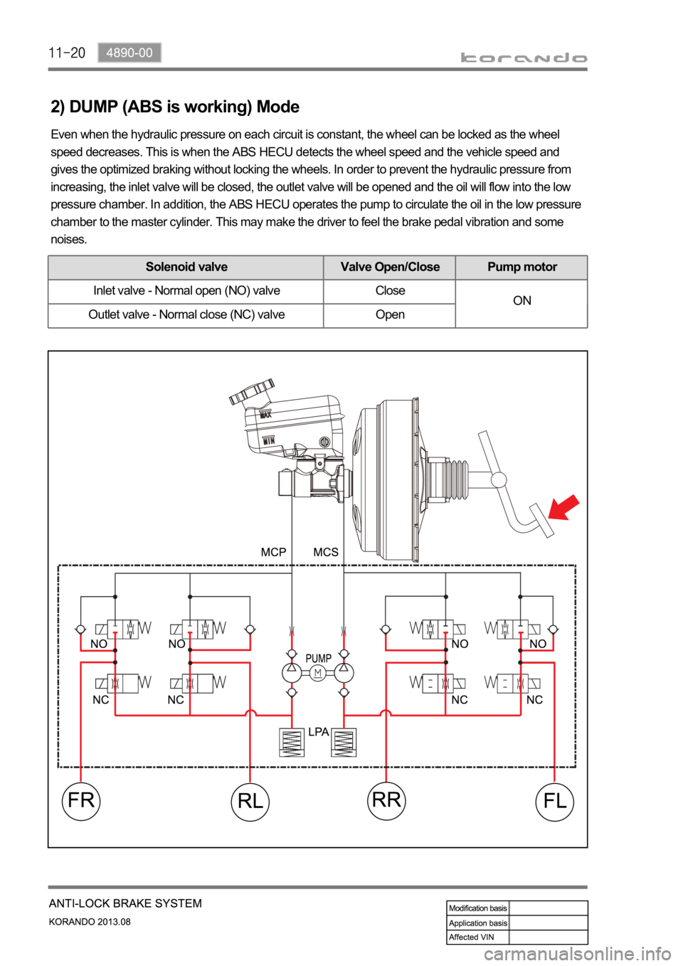
2) DUMP (ABS is working) Mode
Even when the hydraulic pressure on each circuit is constant, the wheel can be locked as the wheel
speed decreases. This is when the ABS HECU detects the wheel speed and the vehicle speed and
gives the optimized braking without locking the wheels. In order to prevent the hydraulic pressure from
increasing, the inlet valve will be closed, the outlet valve will be opened and the oil will flow into the low
pressure chamber. In addition, the ABS HECU operates the pump to circulate the oil in the low pressure
chamber to the master cylinder. This may make the driver to feel the brake pedal vibration and some
noises.
Solenoid valve Valve Open/Close Pump motor
Inlet valve - Normal open (NO) valve Close
ON
Outlet valve - Normal close (NC) valve Open
Page 1117 of 1336
4890-00
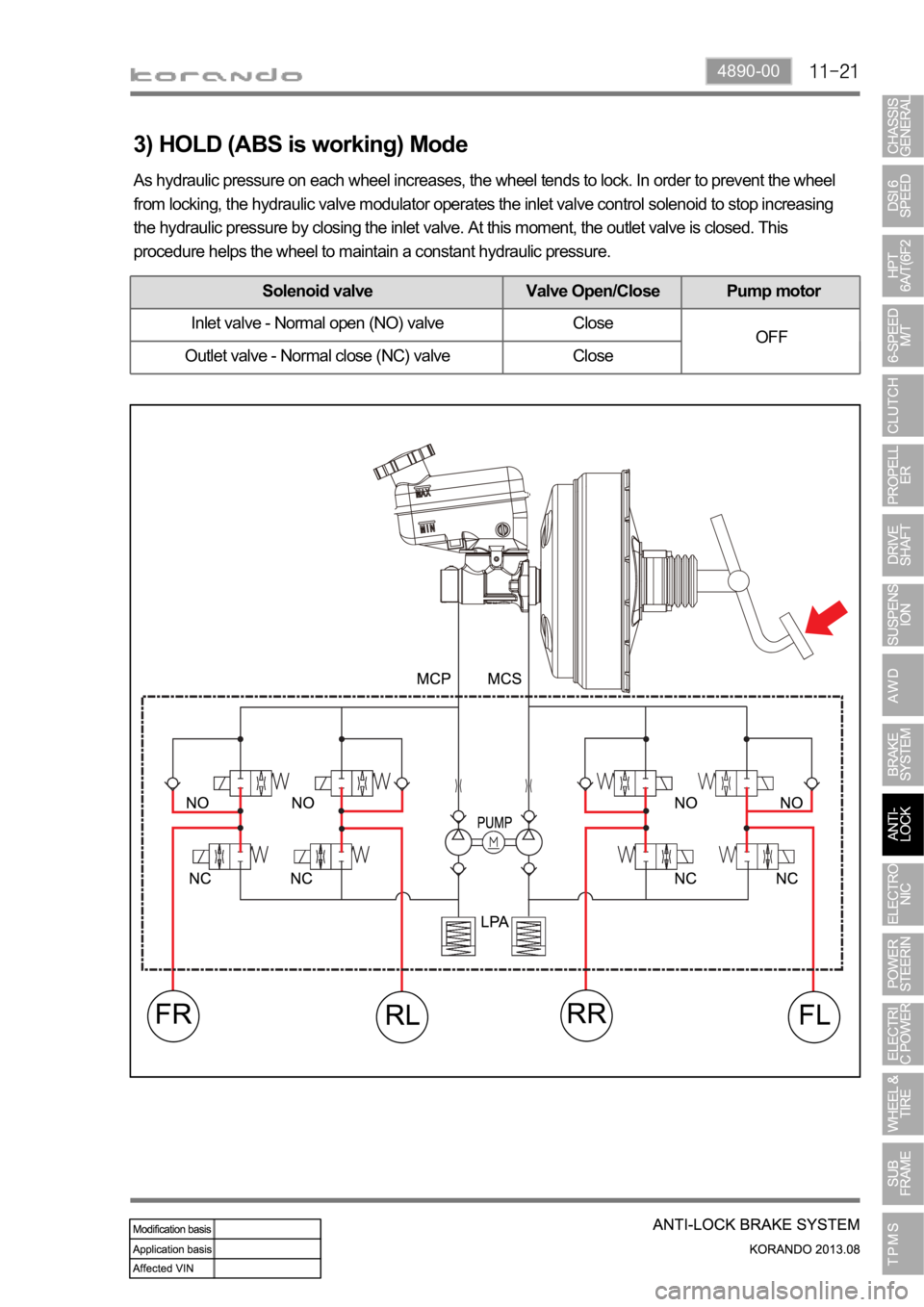
3) HOLD (ABS is working) Mode
As hydraulic pressure on each wheel increases, the wheel tends to lock. In order to prevent the wheel
from locking, the hydraulic valve modulator operates the inlet valve control solenoid to stop increasing
the hydraulic pressure by closing the inlet valve. At this moment, the outlet valve is closed. This
procedure helps the wheel to maintain a constant hydraulic pressure.
Solenoid valve Valve Open/Close Pump motor
Inlet valve - Normal open (NO) valve Close
OFF
Outlet valve - Normal close (NC) valve Close
Page 1118 of 1336
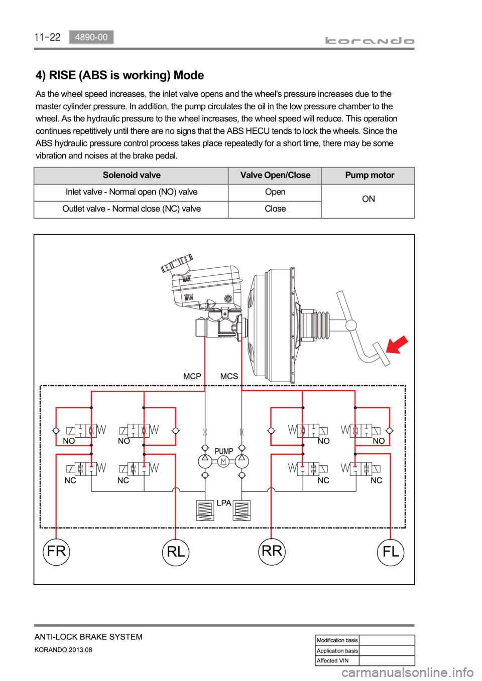
4) RISE (ABS is working) Mode
As the wheel speed increases, the inlet valve opens and the wheel's pressure increases due to the
master cylinder pressure. In addition, the pump circulates the oil in the low pressure chamber to the
wheel. As the hydraulic pressure to the wheel increases, the wheel speed will reduce. This operation
continues repetitively until there are no signs that the ABS HECU tends to lock the wheels. Since the
ABS hydraulic pressure control process takes place repeatedly for a short time, there may be some
vibration and noises at the brake pedal.
Solenoid valve Valve Open/Close Pump motor
Inlet valve - Normal open (NO) valve Open
ON
Outlet valve - Normal close (NC) valve Close
Page 1120 of 1336
0000-00
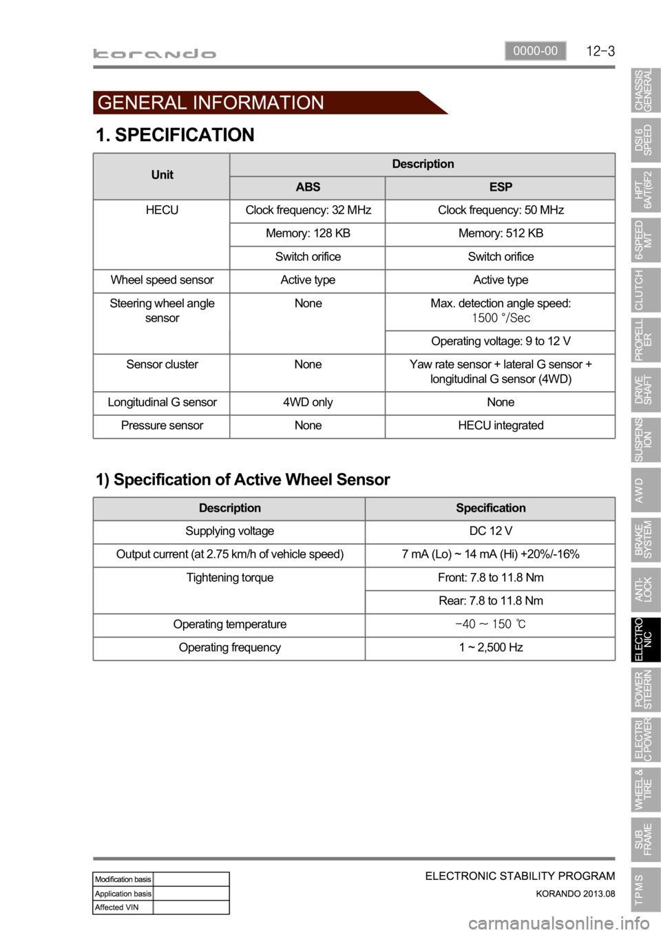
1. SPECIFICATION
1) Specification of Active Wheel Sensor
Description Specification
Supplying voltage DC 12 V
Output current (at 2.75 km/h of vehicle speed) 7 mA (Lo) ~ 14 mA (Hi) +20%/-16%
Tightening torque Front: 7.8 to 11.8 Nm
Rear: 7.8 to 11.8 Nm
Operating temperature
Operating frequency 1 ~ 2,500 Hz
UnitDescription
ABS ESP
HECU Clock frequency: 32 MHz Clock frequency: 50 MHz
Memory: 128 KB Memory: 512 KB
Switch orifice Switch orifice
Wheel speed sensor Active type Active type
Steering wheel angle
sensorNone Max. detection angle speed:
Operating voltage: 9 to 12 V
Sensor cluster None Yaw rate sensor + lateral G sensor +
longitudinal G sensor (4WD)
Longitudinal G sensor 4WD only None
Pressure sensor None HECU integrated
Page 1127 of 1336
5. SYSTEM DESCRIPTION
1) Block Diagram of ESP HECU
Page 1139 of 1336
2) DUMP (ESP is working) Mode
The pressure decreases just before the wheel speed drops and the wheels are locked.
The inlet valve closes and the outlet valve opens as in the ABS HECU and the oil is gathered at the low
pressure chamber while no additional oil is being supplied. Then the pump operates to allow fast oil
drainage. The shuttle valve and the separation valve do not operate while decompression.
Page 1141 of 1336
4) RISE (ESP is working) Mode
The shuttle valve and inlet valve will be open and the separation valve and outlet valve will be closed.
Then, the pump is operated. When ESP operates while the ABS is operating, the pressure will be
increased continuously until just before the corresponding wheel gets locked.
Page 1142 of 1336
0000-00
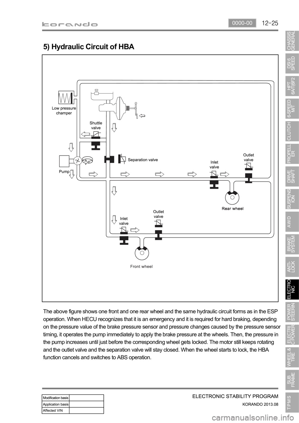
5) Hydraulic Circuit of HBA
The above figure shows one front and one rear wheel and the same hydraulic circuit forms as in the ESP
operation. When HECU recognizes that it is an emergency and it is required for hard braking, depending
on the pressure value of the brake pressure sensor and pressure changes caused by the pressure sensor
timing, it operates the pump immediately to apply the brake pressure at the wheels. Then, the pressure in
the pump increases until just before the corresponding wheel gets locked. The motor still keeps rotating
and the outlet valve and the separation valve will stay closed. When the wheel starts to lock, the HBA
function cancels and switches to ABS operation.
Page 1146 of 1336
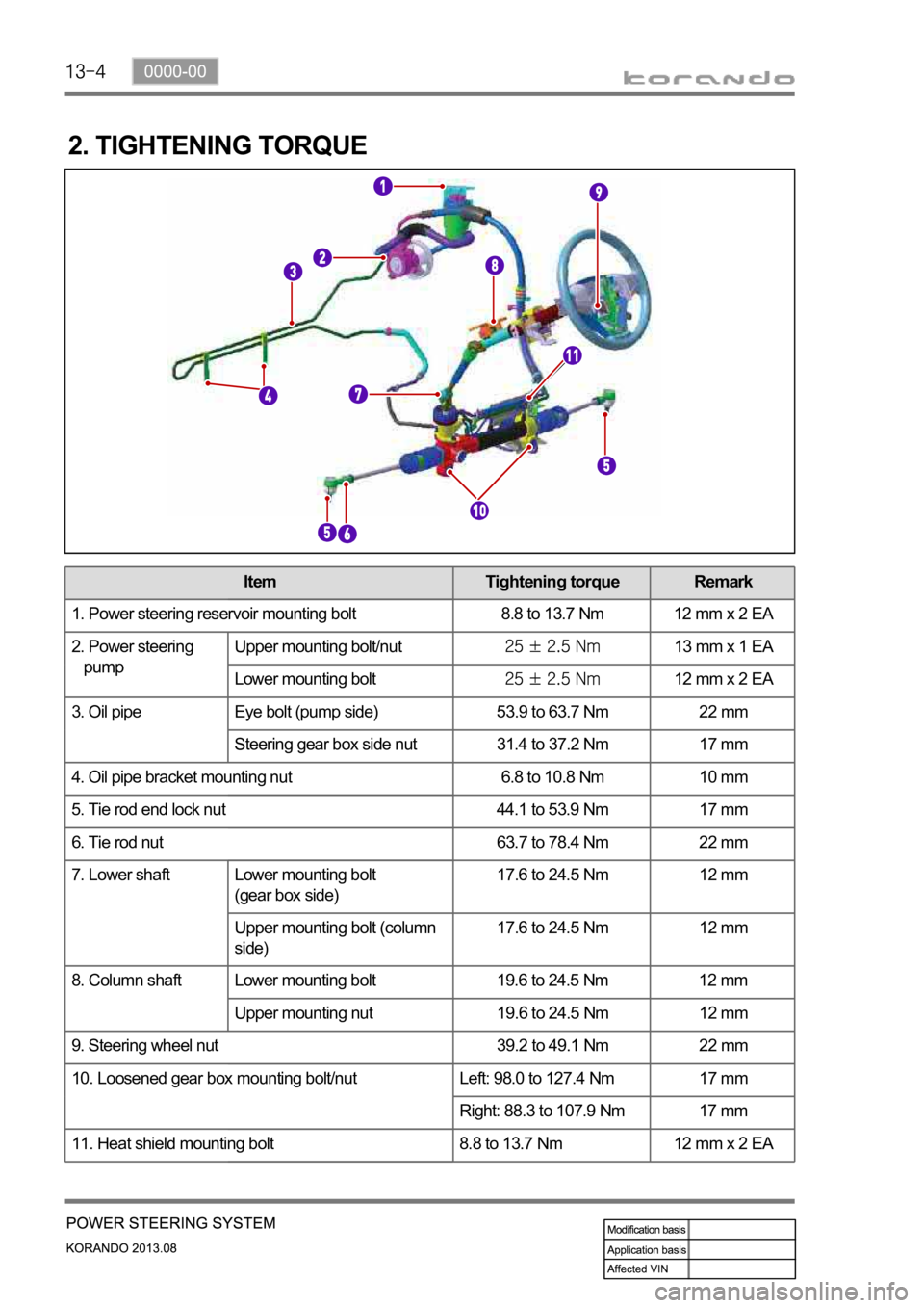
2. TIGHTENING TORQUE
Item Tightening torque Remark
1. Power steering reservoir mounting bolt 8.8 to 13.7 Nm 12 mm x 2 EA
2. Power steering
pumpUpper mounting bolt/nut
13 mm x 1 EA
Lower mounting bolt
12 mm x 2 EA
3. Oil pipe Eye bolt (pump side) 53.9 to 63.7 Nm 22 mm
Steering gear box side nut 31.4 to 37.2 Nm 17 mm
4. Oil pipe bracket mounting nut 6.8 to 10.8 Nm 10 mm
5. Tie rod end lock nut 44.1 to 53.9 Nm 17 mm
6. Tie rod nut 63.7 to 78.4 Nm 22 mm
7. Lower shaft Lower mounting bolt
(gear box side)17.6 to 24.5 Nm 12 mm
Upper mounting bolt (column
side)17.6 to 24.5 Nm 12 mm
8. Column shaft Lower mounting bolt 19.6 to 24.5 Nm 12 mm
Upper mounting nut 19.6 to 24.5 Nm 12 mm
9. Steering wheel nut 39.2 to 49.1 Nm 22 mm
10. Loosened gear box mounting bolt/nut Left: 98.0 to 127.4 Nm 17 mm
Right: 88.3 to 107.9 Nm 17 mm
11. Heat shield mounting bolt 8.8 to 13.7 Nm 12 mm x 2 EA
