turn signal SSANGYONG KORANDO 2013 User Guide
[x] Cancel search | Manufacturer: SSANGYONG, Model Year: 2013, Model line: KORANDO, Model: SSANGYONG KORANDO 2013Pages: 1336, PDF Size: 92.18 MB
Page 571 of 1336
0000-00
(2) Warm-up Control Function
Low voltage
If low voltage is detected by the ECU, the idle speed increases up to 100 rpm selectively under the
driving mode until the ignition switch is turned off. Idle speed control
The idle speed is controlled according to the fuel/air mixture when the engine load is changed, the
power steering wheel is turned to its end, the selector lever is in the "D" position and the A/C compresso
r
is in operation. It is also controlled according to the charge level during the purge control operation.
Ignition timing
The idle speed is controlled according to the fuel/air mixture when the engine load is changed, The
Air conditioner compressor operation
The air conditioner control unit sends the air conditioner operation signal to the ECU to increase the
throttle valve opening amount in order to prevent reduction of the engine speed when the air conditioner
compressor is in operation at idling.
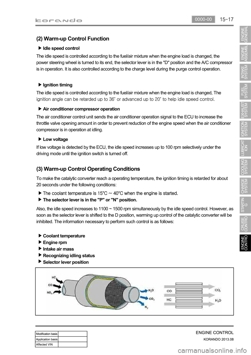
(3) Warm-up Control Operating Conditions
To make the catalytic converter reach a operating temperature, the ignition timing is retarded for about
20 seconds under the following conditions:
The selector lever is in the "P" or "N" position.
Also, the idle speed increases to 1100 ~ 1500 rpm simultaneously by the idle speed control. However, as
soon as the selector lever is shifted to the D position, warming up control of the catalytic converter will be
inhibited. The information necessary to perform such control is as follows:
Coolant temperature
Engine rpm
Intake air mass
Recognizing idling status
Selector lever position
Page 595 of 1336

Swirl control valve
It operates variably in accordance with the
engine load and rpm.
Intake manifold
It is the passage for intake air when the swirl
vale is operating. The T-MAP sensor for
measuring the pressure and temperature of
pressurized air in turbocharger is installed on
the left top of intake manifold.
3. LAYOUT OF INTAKE SYSTEM
1) Overview
The intake system for D20DTF(Low CO2) engine is equipped with a throttle body which includes a flap.
This flap is controlled by an electrical signal to cut off the intake air entering to the engine when the
ignition switch is turned off. The intake manifold contains the swirl control valve and dual port system to
make the optimum turbulence. The T-MAP sensor is located on the left top of the intake manifold and
the HFM sensor for precise control is located at the rear side of air cleaner. To reduce the intake noise
and to improve the intake efficiency, the volume of air cleaner has been increased.
2) Components
Electric throttle body
Page 609 of 1336

0000-00
8. DTC SETTING CONDITIONS
Charge warning lamp ON condition
Turn the ignition ON (Engine stopped)
Open or short circuit of L terminal wiring, open or short internal circuit of alternator (fixed control of
13.8V)
Open or short circuit of F terminal wiring, no feedback output signal 1.
2.
3.
Page 615 of 1336
0000-00
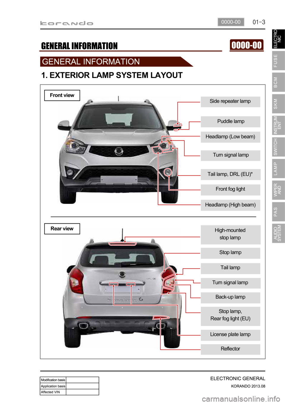
Turn signal lamp
Side repeater lamp
Puddle lamp
1. EXTERIOR LAMP SYSTEM LAYOUT
Headlamp (High beam)
Tail lamp, DRL (EU)*
Front fog light
Tail lamp
High-mounted
stop lamp
Stop lamp
License plate lamp
Turn signal lamp
Stop lamp,
Rear fog light (EU)
Reflector
Front view
Rear view
Headlamp (Low beam)
Back-up lamp
Page 616 of 1336
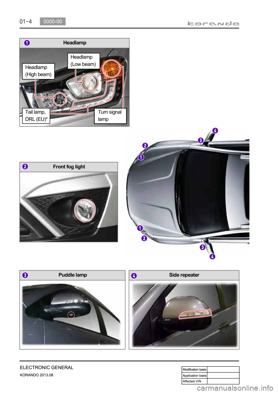
Headlamp
Puddle lamp
Front fog light
Side repeater
Turn signal
lamp
Headlamp
(High beam)
Headlamp
(Low beam)
Tail lamp,
DRL (EU)*
Page 617 of 1336
0000-00
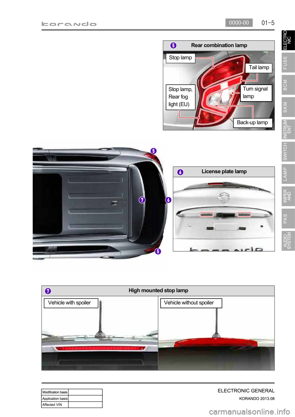
High mounted stop lamp
License plate lamp
Rear combination lamp
Vehicle with spoilerVehicle without spoiler
Back-up lamp
Stop lamp
Tail lamp
Turn signal
lampStop lamp,
Rear fog
light (EU)
Page 637 of 1336
8710-01
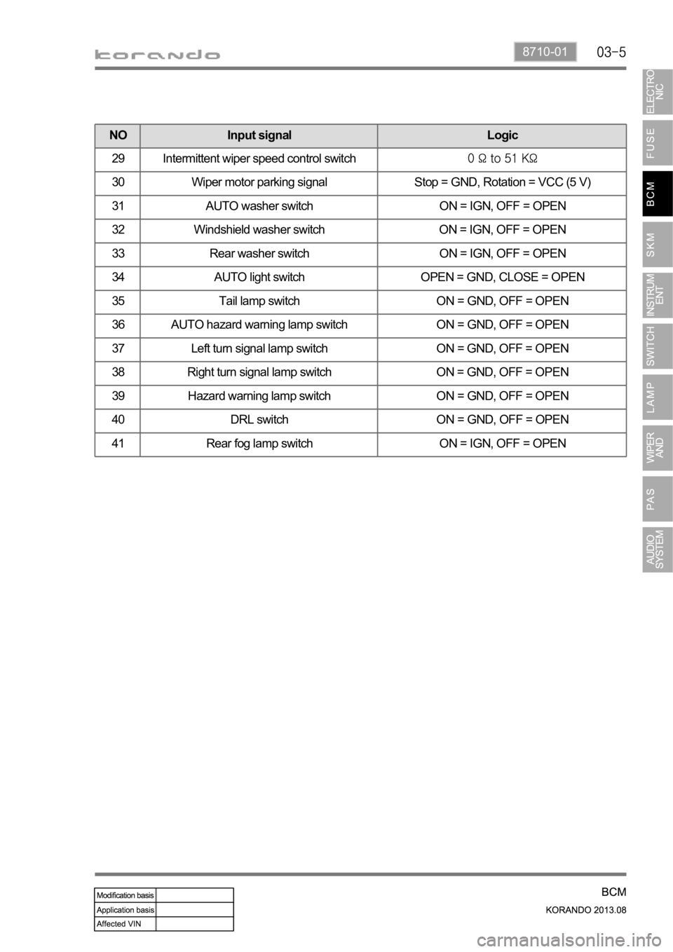
NO Input signal Logic
29 Intermittent wiper speed control switch
30 Wiper motor parking signal Stop = GND, Rotation = VCC (5 V)
31 AUTO washer switch ON = IGN, OFF = OPEN
32 Windshield washer switch ON = IGN, OFF = OPEN
33 Rear washer switch ON = IGN, OFF = OPEN
34 AUTO light switch OPEN = GND, CLOSE = OPEN
35 Tail lamp switch ON = GND, OFF = OPEN
36 AUTO hazard warning lamp switch ON = GND, OFF = OPEN
37 Left turn signal lamp switch ON = GND, OFF = OPEN
38 Right turn signal lamp switch ON = GND, OFF = OPEN
39 Hazard warning lamp switch ON = GND, OFF = OPEN
40 DRL switch ON = GND, OFF = OPEN
41 Rear fog lamp switch ON = IGN, OFF = OPEN
Page 640 of 1336

Item Functionw/o
SKMw/ SKM
17 Flasher unit control Left turn signal lamp control O O
Right turn signal lamp control O O
Hazard warning lamp control O O
AUTO hazard warning lamp control O O
Emergency hazard warning flasher control O O
18 Fog lamp control Fog lamp control O O
19 Immobilizer function Key coding O X
CHALLENGE O X
CAN information O X
20 Folding/unfolding control Folding/unfolding control O O
AUTO folding/unfolding control O O
21 Approach lamp control Approach lamp control (for vehicles without
SKM)OX
Approach lamp control (for vehicles with SKM) X O
22 SKM warning control SKM buzzer control X O
16 System power sleep
modeSystem power sleep mode control O O
Page 647 of 1336
8710-01
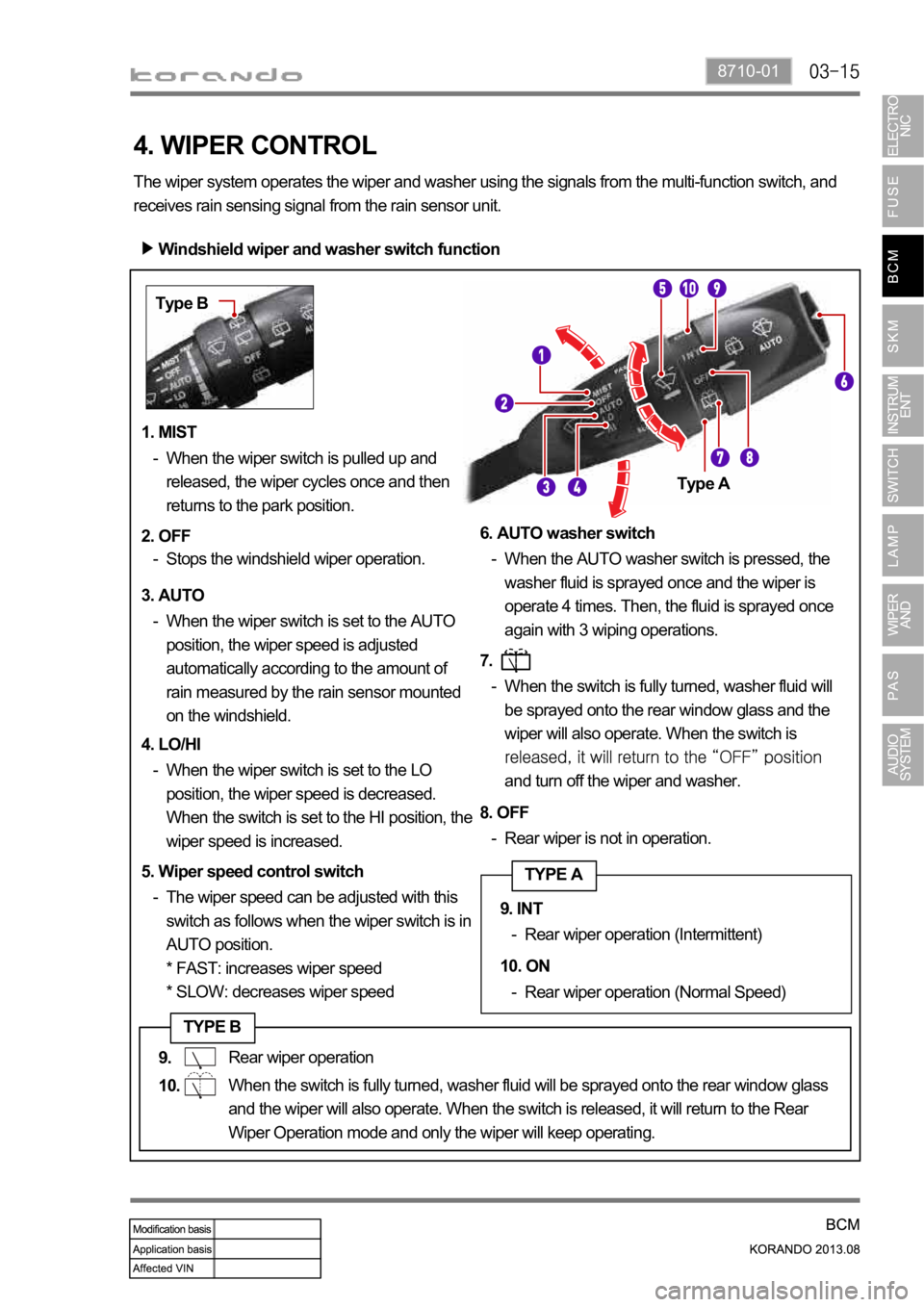
Windshield wiper and washer switch function
The wiper system operates the wiper and washer using the signals from the multi-function switch, and
receives rain sensing signal from the rain sensor unit.
4. WIPER CONTROL
1. MIST
When the wiper switch is pulled up and
released, the wiper cycles once and then
returns to the park position. -
2. OFF
Stops the windshield wiper operation. -
3. AUTO
When the wiper switch is set to the AUTO
position, the wiper speed is adjusted
automatically according to the amount of
rain measured by the rain sensor mounted
on the windshield. -
4. LO/HI
When the wiper switch is set to the LO
position, the wiper speed is decreased.
When the switch is set to the HI position, the
wiper speed is increased. -
5. Wiper speed control switch
The wiper speed can be adjusted with this
switch as follows when the wiper switch is in
AUTO position.
* FAST: increases wiper speed
* SLOW: decreases wiper speed -6. AUTO washer switch
When the AUTO washer switch is pressed, the
washer fluid is sprayed once and the wiper is
operate 4 times. Then, the fluid is sprayed once
again with 3 wiping operations. -
7.
When the switch is fully turned, washer fluid will
be sprayed onto the rear window glass and the
wiper will also operate. When the switch is
and turn off the wiper and washer. -
8. OFF
Rear wiper is not in operation. -
9. Rear wiper operation (Intermittent) -
10. Rear wiper operation (Normal Speed) -
Type B
Type A
TYPE A
TYPE B
Rear wiper operation
When the switch is fully turned, washer fluid will be sprayed onto the rear window glass
and the wiper will also operate. When the switch is released, it will return to the Rear
Wiper Operation mode and only the wiper will keep operating.9. INT
10. ON
Page 648 of 1336

Windshield wiper MIST operation
The ignition is turned ON.
The MIST switch is turned ON for 0.1 seconds or more.
The wiper LO/HI relay is activated 0.1 seconds (T1) after the MIST switch is turned ON.
The wiper LO relay is deactivated when the MIST switch is turned OFF and the wiper motor parking
signal is input. A.
B.
C.
D. Operation 1.
The wiper HI relay is activated when the MIST switch signal is input. If no signal from the MIST
switch is input, the wiper LO relay is activated.