engine oil SSANGYONG KORANDO 2013 Owner's Manual
[x] Cancel search | Manufacturer: SSANGYONG, Model Year: 2013, Model line: KORANDO, Model: SSANGYONG KORANDO 2013Pages: 1336, PDF Size: 92.18 MB
Page 294 of 1336
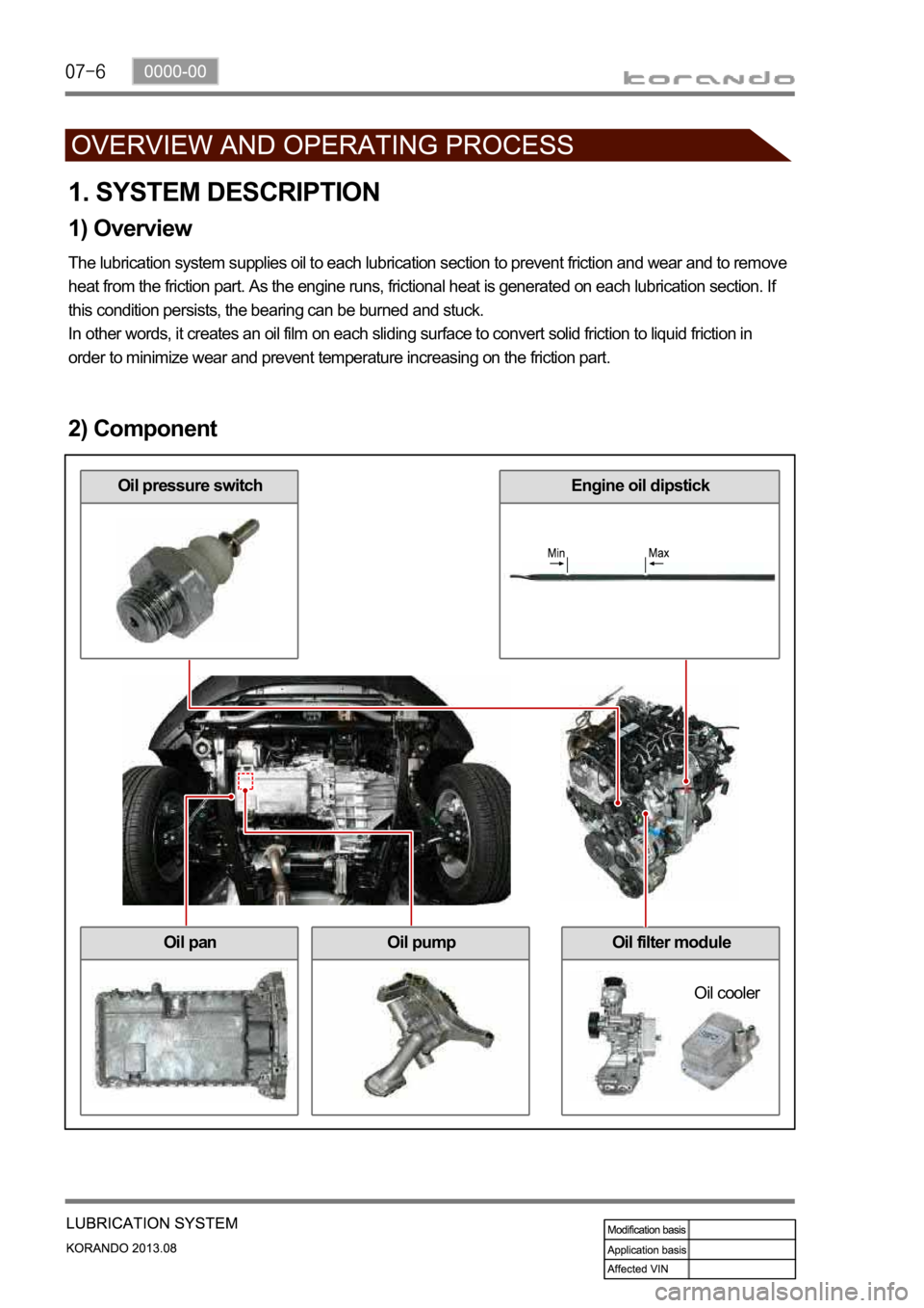
1. SYSTEM DESCRIPTION
1) Overview
The lubrication system supplies oil to each lubrication section to prevent friction and wear and to remove
heat from the friction part. As the engine runs, frictional heat is generated on each lubrication section. If
this condition persists, the bearing can be burned and stuck.
In other words, it creates an oil film on each sliding surface to convert solid friction to liquid friction in
order to minimize wear and prevent temperature increasing on the friction part.
2) Component
Oil pressure switchEngine oil dipstick
Oil panOil pumpOil filter module
Oil cooler
Page 297 of 1336
0000-00
3. LUBRICATION
1)Anti-friction
The oil makes a thin film on the surface of sliding components to reduce the wear due to friction.
2)Cooling
The friction makes the heat on the components. The oil absorbs the heat and radiates it or cools it down.
3) Sealing
The piston ring on the piston seals the cylinder. The oil gets into the clearance in piston ring to secure
the sealing for compression pressure and combustion gas.
4) Anti-corrosion
The oil generates the thin film on the surface of components to prevent the material from contacting with
air, water and corrosive gas.
5) Cleaning
The oil transfers the residue of material due to friction, oxidized substance, and carbonized substance
while circulating in the engine by oil pump.
Page 303 of 1336
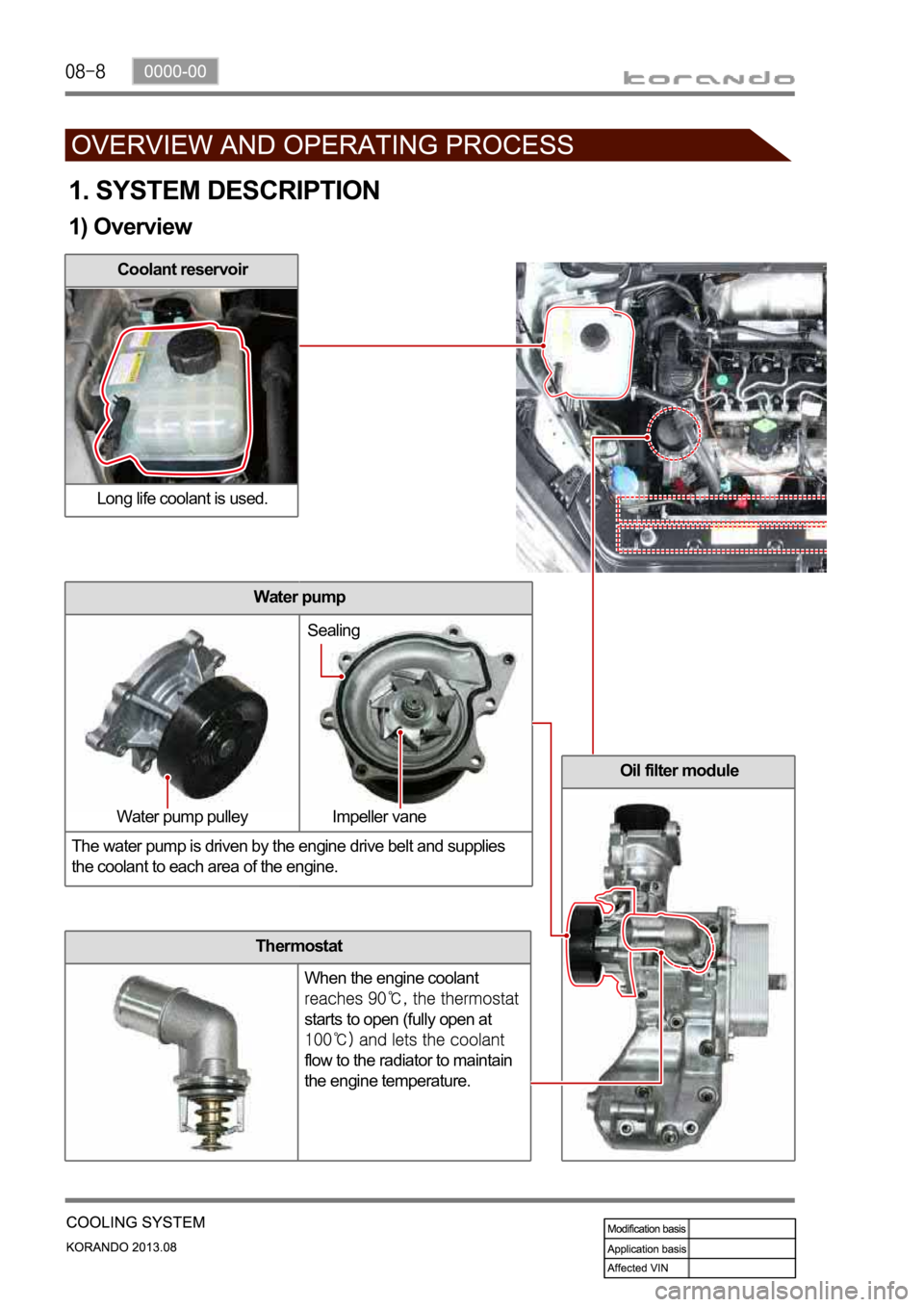
Oil filter module
Thermostat
When the engine coolant
starts to open (fully open at
flow to the radiator to maintain
the engine temperature.
1. SYSTEM DESCRIPTION
1) Overview
Coolant reservoir
Long life coolant is used.
Water pump
The water pump is driven by the engine drive belt and supplies
the coolant to each area of the engine.
Water pump pulley Impeller vaneSealing
Page 308 of 1336
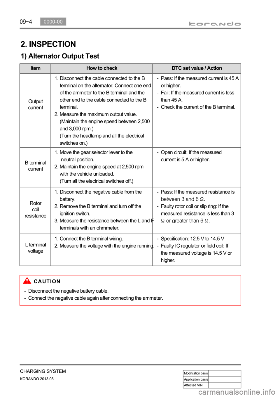
2. INSPECTION
1) Alternator Output Test
Item How to check DTC set value / Action
Output
current
B terminal
current
Rotor
coil
resistance
L terminal
voltage
Disconnect the cable connected to the B
terminal on the alternator. Connect one end
of the ammeter to the B terminal and the
other end to the cable connected to the B
terminal.
Measure the maximum output value.
(Maintain the engine speed between 2,500
and 3,000 rpm.)
(Turn the headlamp and all the electrical
switches on.) 1.
2.Pass: If the measured current is 45 A
or higher.
Fail: If the measured current is less
than 45 A.
Check the current of the B terminal. -
-
-
Move the gear selector lever to the
neutral position.
Maintain the engine speed at 2,500 rpm
with the vehicle unloaded.
(Turn all the electrical switches off.) 1.
2.Open circuit: If the measured
current is 5 A or higher. -
Disconnect the negative cable from the
battery.
Remove the B terminal and turn off the
ignition switch.
Measure the resistance between the L and F
terminals with an ohmmeter. 1.
2.
3.Pass: If the measured resistance is
Faulty rotor coil or slip ring: If the
measured resistance is less than 3
-
-
Connect the B terminal wiring.
Measure the voltage with the engine running. 1.
2.Specification: 12.5 V to 14.5 V
Faulty IC regulator or field coil: If
the measured voltage is 14.5 V or
higher. -
-
Disconnect the negative battery cable.
Connect the negative cable again after connecting the ammeter. -
-
Page 360 of 1336
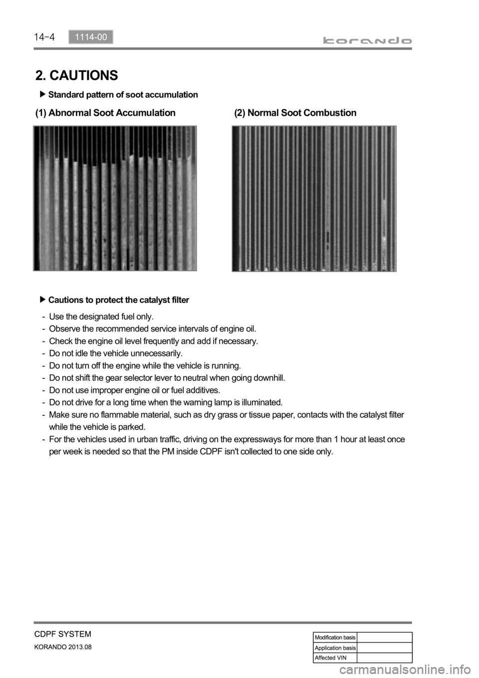
2. CAUTIONS
Standard pattern of soot accumulation
(1) Abnormal Soot Accumulation(2) Normal Soot Combustion
Cautions to protect the catalyst filter
Use the designated fuel only.
Observe the recommended service intervals of engine oil.
Check the engine oil level frequently and add if necessary.
Do not idle the vehicle unnecessarily.
Do not turn off the engine while the vehicle is running.
Do not shift the gear selector lever to neutral when going downhill.
Do not use improper engine oil or fuel additives.
Do not drive for a long time when the warning lamp is illuminated.
Make sure no flammable material, such as dry grass or tissue paper, contacts with the catalyst filter
while the vehicle is parked.
For the vehicles used in urban traffic, driving on the expressways for more than 1 hour at least once
per week is needed so that the PM inside CDPF isn't collected to one side only. -
-
-
-
-
-
-
-
-
-
Page 371 of 1336
1114-00
8. CAUTIONS
1) Designated Engine Oil for CDPF (Low Ash Oil)
Need to use the designated engine oil for CDPF 1.
The smoke from the vehicle may generate the particle material in the ambient air. CDPF is the
device to reduce the smoke by collecting and recycling it. To ensure the performance of CDPF,
the designated engine oil should be used.
The smoke including combusted sulfur in fuel cannot be recycled in CDPF. This smoke
generates the ash, resulting in clogging the filter. -
-
Advantages when using the designated engine oil for CDPF 2.
Reduces the amount of ash
Improves the fuel economy and reduces the CO2
Increases the life span of engine oil
Available for all engines (diesel and gasoline) -
-
-
-
Problems when using non-designated engine oil for CDPF 3.
Decreases the life span of engine oil due to accumulated ash in DPF (around 30%)
Decreases the fuel economy due to friction resistance, exhaust gas resistance and frequent
recycling process of DPF -
-
The fule containing high sulfur may cause the same problems.
2) Do Not Use the Fuel Containing High Sulfur
Producing white smoke during recycling 1.
The sulfur in exhaust gas is changed to sulfate gas during exhaust process. This sulfate gas is
shown as white smoke. -
Producing odor during recycling 2.
The sulfur after oxidation may produce the odor. -
Accumulation of ash 3.
The sulfur accumulated in DPF cannot be recycled. It reduces the life span of DPF. -
3) White Smoke
The white smoke can be generated when the exhaust gas is recycled in DPF. There are two reasons as
below.
Saturated vapor
Sulfate 1.
2.
Page 405 of 1336
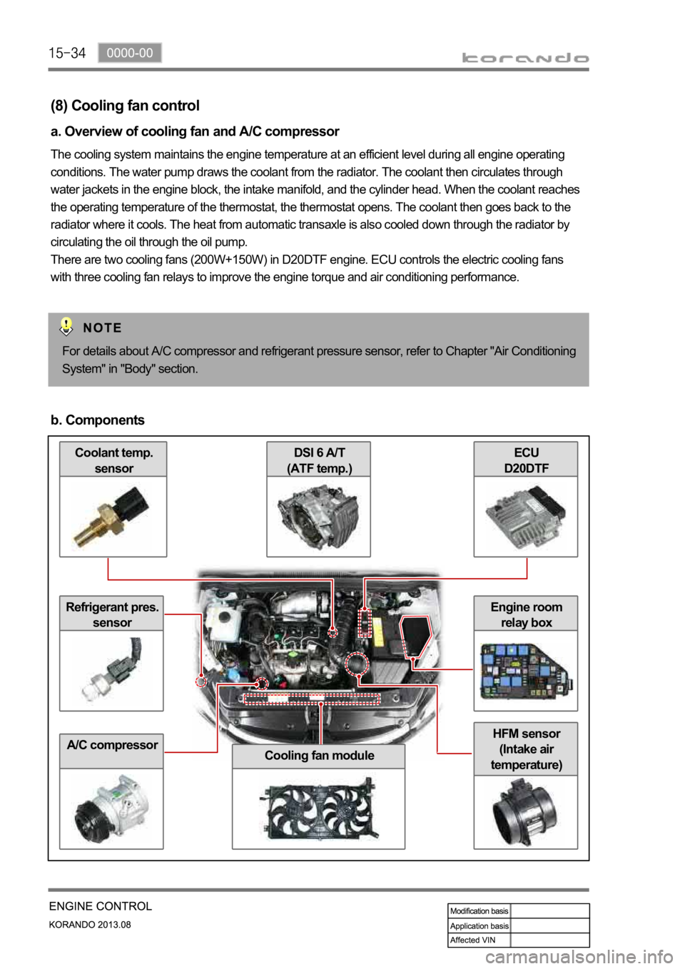
Coolant temp.
sensor
Refrigerant pres.
sensor
A/C compressor
ECU
D20DTFDSI 6 A/T
(ATF temp.)
Cooling fan module
HFM sensor
(Intake air
temperature)
Engine room
relay box
(8) Cooling fan control
a. Overview of cooling fan and A/C compressor
The cooling system maintains the engine temperature at an efficient level during all engine operating
conditions. The water pump draws the coolant from the radiator. The coolant then circulates through
water jackets in the engine block, the intake manifold, and the cylinder head. When the coolant reaches
the operating temperature of the thermostat, the thermostat opens. The coolant then goes back to the
radiator where it cools. The heat from automatic transaxle is also cooled down through the radiator by
circulating the oil through the oil pump.
There are two cooling fans (200W+150W) in D20DTF engine. ECU controls the electric cooling fans
with three cooling fan relays to improve the engine torque and air conditioning performance.
For details about A/C compressor and refrigerant pressure sensor, refer to Chapter "Air Conditioning
System" in "Body" section.
b. Components
Page 418 of 1336
0000-00
e. Cautions
Use only specified Engine Oil (approved by MB Sheet 229.51) for CDPF. -
1. Use only specified engine oil (Low Ash Oil)
The vehicle equipped with CDPF should use specific engine oil to improve the engine performance
and fuel economy, and ensure the service life of CDPF. -
2. Issue with normal engine oil
Sulfur, one of the contents of engine oil is burned and generates soot that is not regenerated by the
DPF. This remains on the filter as ashes and keeps accumulating. Eventually, this ashes will block the
filter. -
3. Benefit for specified engine oil
Minimized the sulfur content of engine oil which reduces the service life.
Improved fuel economy and emission level of CO2 with high performance and low viscosity.
Increased service life of engine oil with high resistance to temperature. -
-
-
4. Problems when using unspecified engine oil
The service life of filter may be reduced by 30% or more by the ashes accumulated on the filter.
The fuel economy may be reduced because of engine rolling resistance, frequent regeneration of
DPF. -
-
These problems are also caused by oil with high sulfur content, such as tax exemption oil and
heating oil, etc. *
Page 423 of 1336
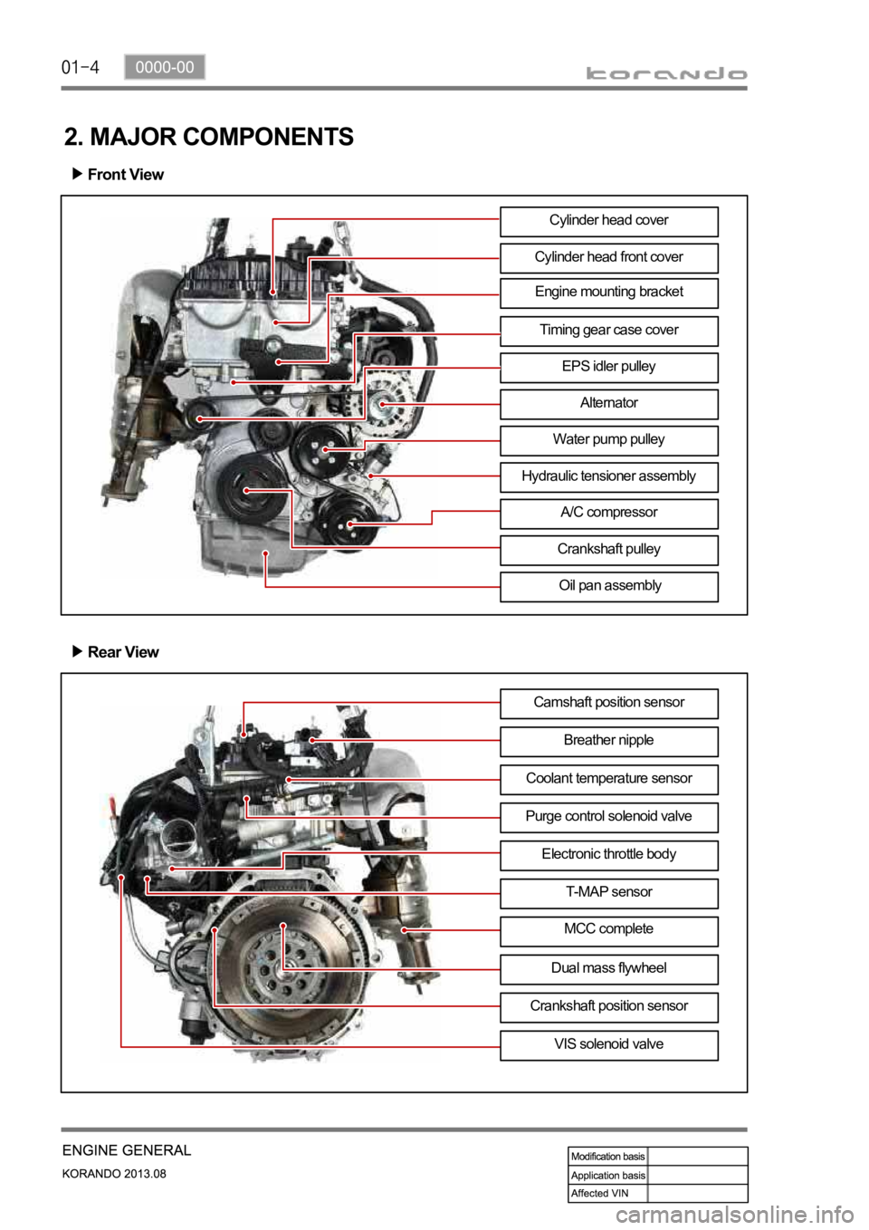
Engine mounting bracket
2. MAJOR COMPONENTS
Front View
Cylinder head front cover
Timing gear case cover
EPS idler pulley
Alternator
Water pump pulley
A/C compressor
Crankshaft pulley
Oil pan assembly
Rear View
Camshaft position sensor
Breather nipple
Purge control solenoid valveCoolant temperature sensor
Electronic throttle body
T-MAP sensor
MCC complete
VIS solenoid valve Cylinder head cover
Dual mass flywheel
Crankshaft position sensor
Hydraulic tensioner assembly
Page 426 of 1336
0000-00
3) General Instructions
Before lifting up the vehicle with a lift, correctly support the lifting points.
When using a jack, park the vehicle on a level ground and place the wheel chocks under the tires.
Position the jack under the frame and lift up the vehicle and then support with chassis stand before
service work.
Make sure to disconnect the negative (-) cable from the battery to prevent any damage to electric
systems.
If you have to work on vehicle, cover the seats and floor with protection covers to avoid any
damage and contamination.
Brake fluid and anti-freeze can damage the painted surface of body. So carefully handle them
during service work.
To improve the efficiency of service work, use only recommended and specified tools.
Use only Ssangyong genuine spare parts.
Never reuse the cotter pin, gasket, O-ring, oil seal, lock washer and self-locking nut. Replace them
with new ones. If reused, normal functions cannot be maintained.
Store the disassembled parts as a set based on disassembly order and unit.
Pay particular attention not to miss or mix the fasteners.
If necessary, especially for inspection, clean the removed parts completely.
Apply the oil or grease on the running and sliding surfeces before installation. Use the specified
sealant and gasket to prevent leakage if necessary.
Tighten the fasteners to the specified tightening torque.
As a final stage of service work, check if the serviced system is working properly and the problem
has been eliminated clearly. (1)
(2)
(3)
(4)
(5)
(6)
(7)
(8)
(9)
(10)
(11)
(12)
(13)
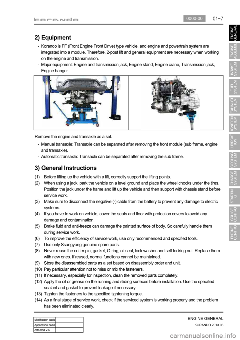
(14) Remove the engine and transaxle as a set.
Manual transaxle: Transaxle can be separated after removing the front module (sub frame, engine
and transaxle).
Automatic transaxle: Transaxle can be separated after removing the sub frame. -
-
2) Equipment
Korando is FF (Front Engine Front Drive) type vehicle, and engine and powertrain system are
integrated into a module. Therefore, 2-post lift and general equipment are necessary when working
on the engine and transmission.
Major equipment: Engine and transmission jack, Engine stand, Engine crane, Transmission jack,
Engine hanger -
-