engine oil SSANGYONG KORANDO 2013 Repair Manual
[x] Cancel search | Manufacturer: SSANGYONG, Model Year: 2013, Model line: KORANDO, Model: SSANGYONG KORANDO 2013Pages: 1336, PDF Size: 92.18 MB
Page 1007 of 1336
3680-01
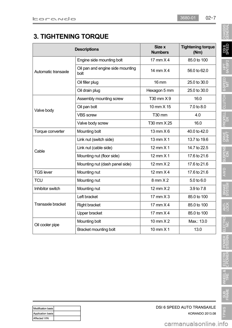
3. TIGHTENING TORQUE
DescriptionsSize x
NumbersTightening torque
(Nm)
Automatic transaxleEngine side mounting bolt 17 mm X 4 85.0 to 100
Oil pan and engine side mounting
bolt14 mm X 4 56.0 to 62.0
Oil filler plug 16 mm 25.0 to 30.0
Oil drain plug Hexagon 5 mm 25.0 to 30.0
Valve bodyAssembly mounting screw T30 mm X 9 16.0
Oil pan bolt 10 mm X 15 7.0 to 8.0
VBS screw T30 mm 4.0
Valve body screw T30 mm X 25 16.0
Torque converter Mounting bolt 13 mm X 6 40.0 to 42.0
CableLink nut (switch side) 13 mm X 1 13.7 to 19.6
Link nut (cable side) 12 mm X 1 14.7 to 22.5
Mounting nut (floor side) 12 mm X 1 17.6 to 21.6
Mounting nut (dash panel side) 12 mm X 2 17.6 to 21.6
TGS lever Mounting nut 12 mm X 4 17.6 to 21.6
TCU Mounting nut 8 mm X 2 5.0 to 6.0
Inhibitor switch Mounting nut 12 mm X 2 3.9 to 7.8
Transaxle bracketLeft bracket 17 mm X 3 85.0 to 100
Right bracket 17 mm X 4 85.0 to 100
Upper bracket 17 mm X 4 85.0 to 100
Oil cooler pipeMounting bolt 10 mm X 2 Max.: 13.0
Bracket mounting bolt 10 mm X 1 13.0
Page 1008 of 1336
1. OVERVIEW
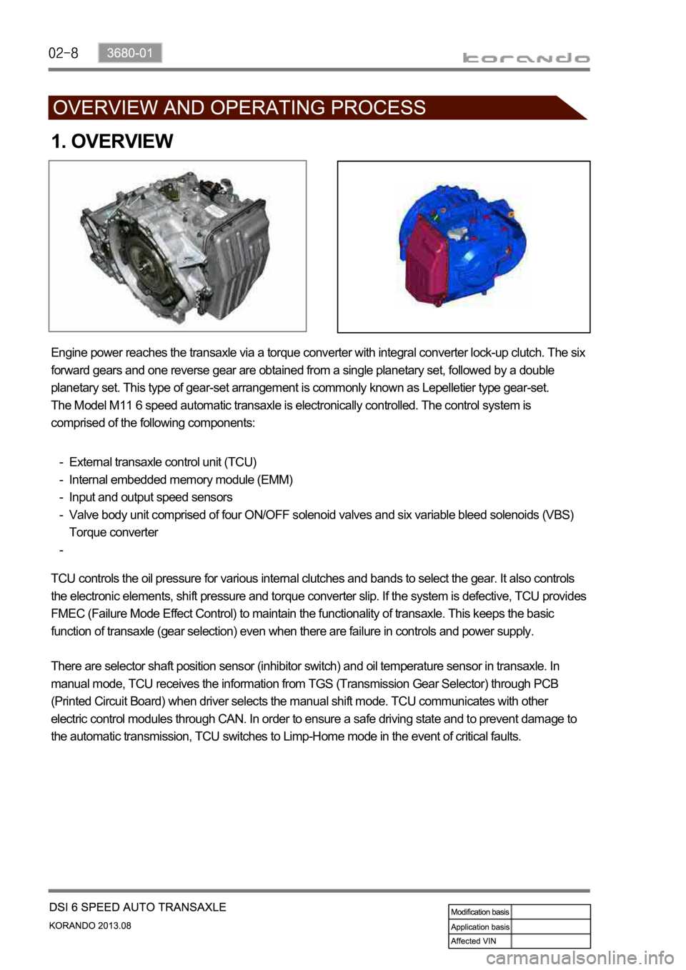
Engine power reaches the transaxle via a torque converter with integral converter lock-up clutch. The six
forward gears and one reverse gear are obtained from a single planetary set, followed by a double
planetary set. This type of gear-set arrangement is commonly known as Lepelletier type gear-set.
The Model M11 6 speed automatic transaxle is electronically controlled. The control system is
comprised of the following components:
External transaxle control unit (TCU)
Internal embedded memory module (EMM)
Input and output speed sensors
Valve body unit comprised of four ON/OFF solenoid valves and six variable bleed solenoids (VBS)
Torque converter -
-
-
-
-
TCU controls the oil pressure for various internal clutches and bands to select the gear. It also controls
the electronic elements, shift pressure and torque converter slip. If the system is defective, TCU provides
FMEC (Failure Mode Effect Control) to maintain the functionality of transaxle. This keeps the basic
function of transaxle (gear selection) even when there are failure in controls and power supply.
There are selector shaft position sensor (inhibitor switch) and oil temperature sensor in transaxle. In
manual mode, TCU receives the information from TGS (Transmission Gear Selector) through PCB
(Printed Circuit Board) when driver selects the manual shift mode. TCU communicates with other
electric control modules through CAN. In order to ensure a safe driving state and to prevent damage to
the automatic transmission, TCU switches to Limp-Home mode in the event of critical faults.
Page 1014 of 1336
5. TRANSAXLE ELECTRONIC CONTROL SYSTEM
1) General Information
The transmission control unit (TCU) and its input/output network control the following transmission
operations:
Shift timing
Line pressure
Clutch pressure (shift feel)
Torque converter clutch -
-
-
-
also uses these signals when determining transaxle operating strategy. Using all of these input signals,
the TCU can determine when the time and conditions are right for a shift, or when to apply or release the
torque converter clutch. It will also determine the pressure needed to optimise shift feel. To accomplish
this, the TCU operates six variable bleed control solenoids and four on/off solenoids to control transaxle
operation.
2) TCU (Transmission Control Unit)
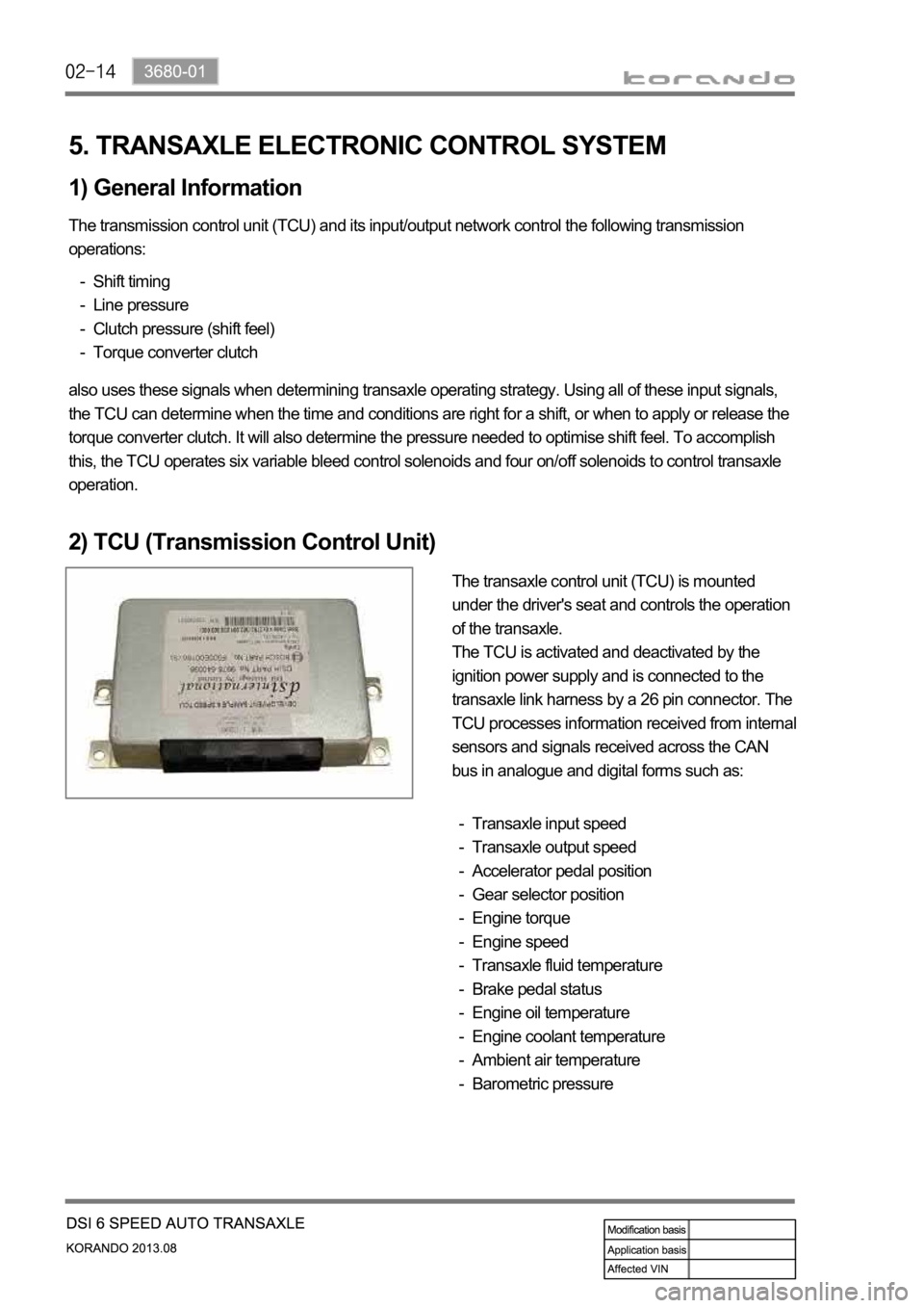
The transaxle control unit (TCU) is mounted
under the driver's seat and controls the operation
of the transaxle.
The TCU is activated and deactivated by the
ignition power supply and is connected to the
transaxle link harness by a 26 pin connector. The
TCU processes information received from internal
sensors and signals received across the CAN
bus in analogue and digital forms such as:
Transaxle input speed
Transaxle output speed
Accelerator pedal position
Gear selector position
Engine torque
Engine speed
Transaxle fluid temperature
Brake pedal status
Engine oil temperature
Engine coolant temperature
Ambient air temperature
Barometric pressure -
-
-
-
-
-
-
-
-
-
-
-
Page 1034 of 1336
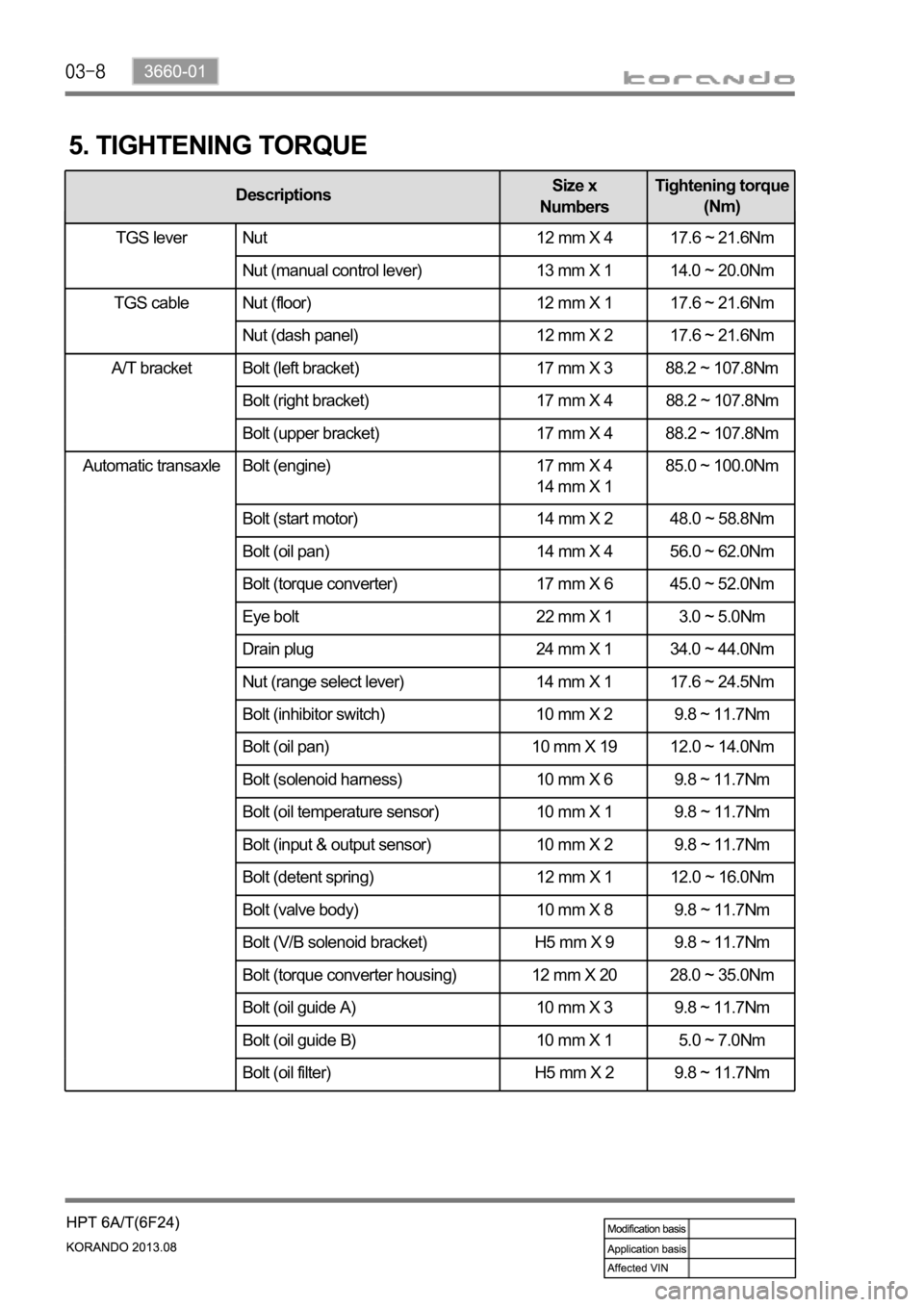
Automatic transaxle Bolt (engine) 17 mm X 4
14 mm X 1 85.0 ~ 100.0Nm
Bolt (start motor) 14 mm X 2 48.0 ~ 58.8Nm
Bolt (oil pan) 14 mm X 4 56.0 ~ 62.0Nm
Bolt (torque converter) 17 mm X 6 45.0 ~ 52.0Nm
Eye bolt 22 mm X 1 3.0 ~ 5.0Nm
Drain plug 24 mm X 1 34.0 ~ 44.0Nm
Nut (range select lever) 14 mm X 1 17.6 ~ 24.5Nm
Bolt (inhibitor switch) 10 mm X 2 9.8 ~ 11.7Nm
Bolt (oil pan) 10 mm X 19 12.0 ~ 14.0Nm
Bolt (solenoid harness) 10 mm X 6 9.8 ~ 11.7Nm
Bolt (oil temperature sensor) 10 mm X 1 9.8 ~ 11.7Nm
Bolt (input & output sensor) 10 mm X 2 9.8 ~ 11.7Nm
Bolt (detent spring) 12 mm X 1 12.0 ~ 16.0Nm
Bolt (valve body) 10 mm X 8 9.8 ~ 11.7Nm
Bolt (V/B solenoid bracket) H5 mm X 9 9.8 ~ 11.7Nm
Bolt (torque converter housing) 12 mm X 20 28.0 ~ 35.0Nm
Bolt (oil guide A) 10 mm X 3 9.8 ~ 11.7Nm
Bolt (oil guide B) 10 mm X 1 5.0 ~ 7.0Nm
Bolt (oil filter) H5 mm X 2 9.8 ~ 11.7Nm
5. TIGHTENING TORQUE
DescriptionsSize x
NumbersTightening torque
(Nm)
TGS lever Nut 12 mm X 4 17.6 ~ 21.6Nm
Nut (manual control lever) 13 mm X 1 14.0 ~ 20.0Nm
Nut (floor) 12 mm X 1 17.6 ~ 21.6Nm
Nut (dash panel) 12 mm X 2 17.6 ~ 21.6Nm
A/T bracket Bolt (left bracket) 17 mm X 3 88.2 ~ 107.8Nm
Bolt (right bracket) 17 mm X 4 88.2 ~ 107.8Nm
Bolt (upper bracket) 17 mm X 4 88.2 ~ 107.8Nm
TGS lever
TGS cable
Page 1043 of 1336
3660-01
5. TRANSAXLE ELECTRONIC CONTROL SYSTEM
1) General Information
The transmission control unit (TCU) and its input/output network control the following transmission
operations:
Shift timing
Line pressure
Clutch pressure (shift feel)
Torque converter clutch -
-
-
-
also uses these signals when determining transaxle operating strategy. Using all of these input signals,
the TCU can determine when the time and conditions are right for a shift, or when to apply or release the
torque converter clutch. It will also determine the pressure needed to optimise shift feel.
2) TCU (Transmission Control Unit)
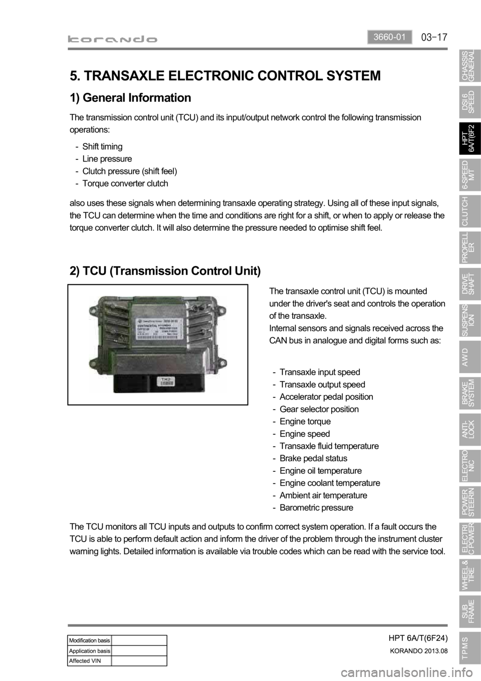
The transaxle control unit (TCU) is mounted
under the driver's seat and controls the operation
of the transaxle.
Internal sensors and signals received across the
CAN bus in analogue and digital forms such as:
Transaxle input speed
Transaxle output speed
Accelerator pedal position
Gear selector position
Engine torque
Engine speed
Transaxle fluid temperature
Brake pedal status
Engine oil temperature
Engine coolant temperature
Ambient air temperature
Barometric pressure -
-
-
-
-
-
-
-
-
-
-
-
The TCU monitors all TCU inputs and outputs to confirm correct system operation. If a fault occurs the
TCU is able to perform default action and inform the driver of the problem through the instrument cluster
warning lights. Detailed information is available via trouble codes which can be read with the service tool.
Page 1070 of 1336
0000-00
3. DUAL MASS FLYWHEEL (DMF)
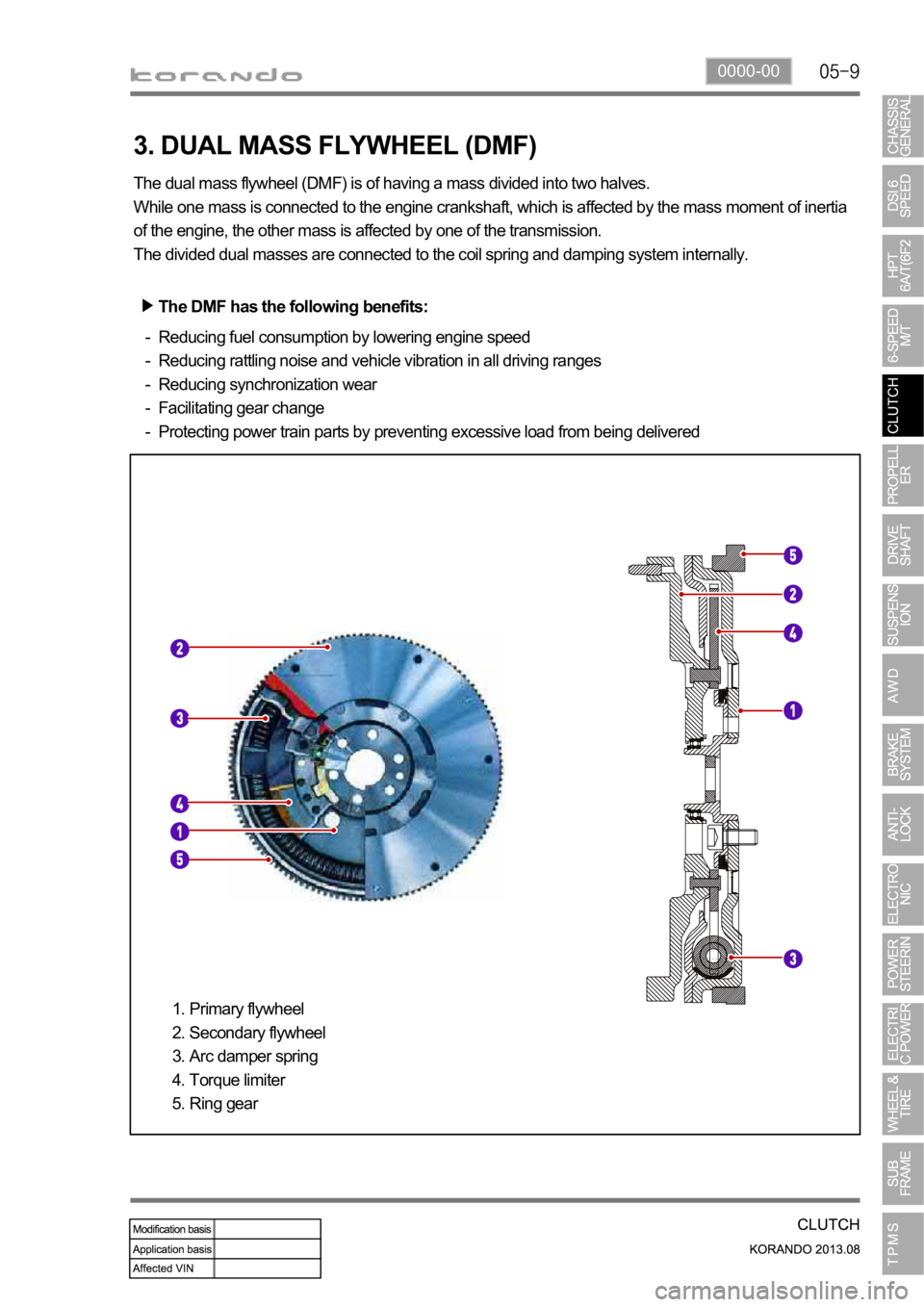
The dual mass flywheel (DMF) is of having a mass divided into two halves.
While one mass is connected to the engine crankshaft, which is affected by the mass moment of inertia
of the engine, the other mass is affected by one of the transmission.
The divided dual masses are connected to the coil spring and damping system internally.
The DMF has the following benefits:
Reducing fuel consumption by lowering engine speed
Reducing rattling noise and vehicle vibration in all driving ranges
Reducing synchronization wear
Facilitating gear change
Protecting power train parts by preventing excessive load from being delivered -
-
-
-
-
Primary flywheel
Secondary flywheel
Arc damper spring
Torque limiter
Ring gear 1.
2.
3.
4.
5.
Page 1149 of 1336
0000-00
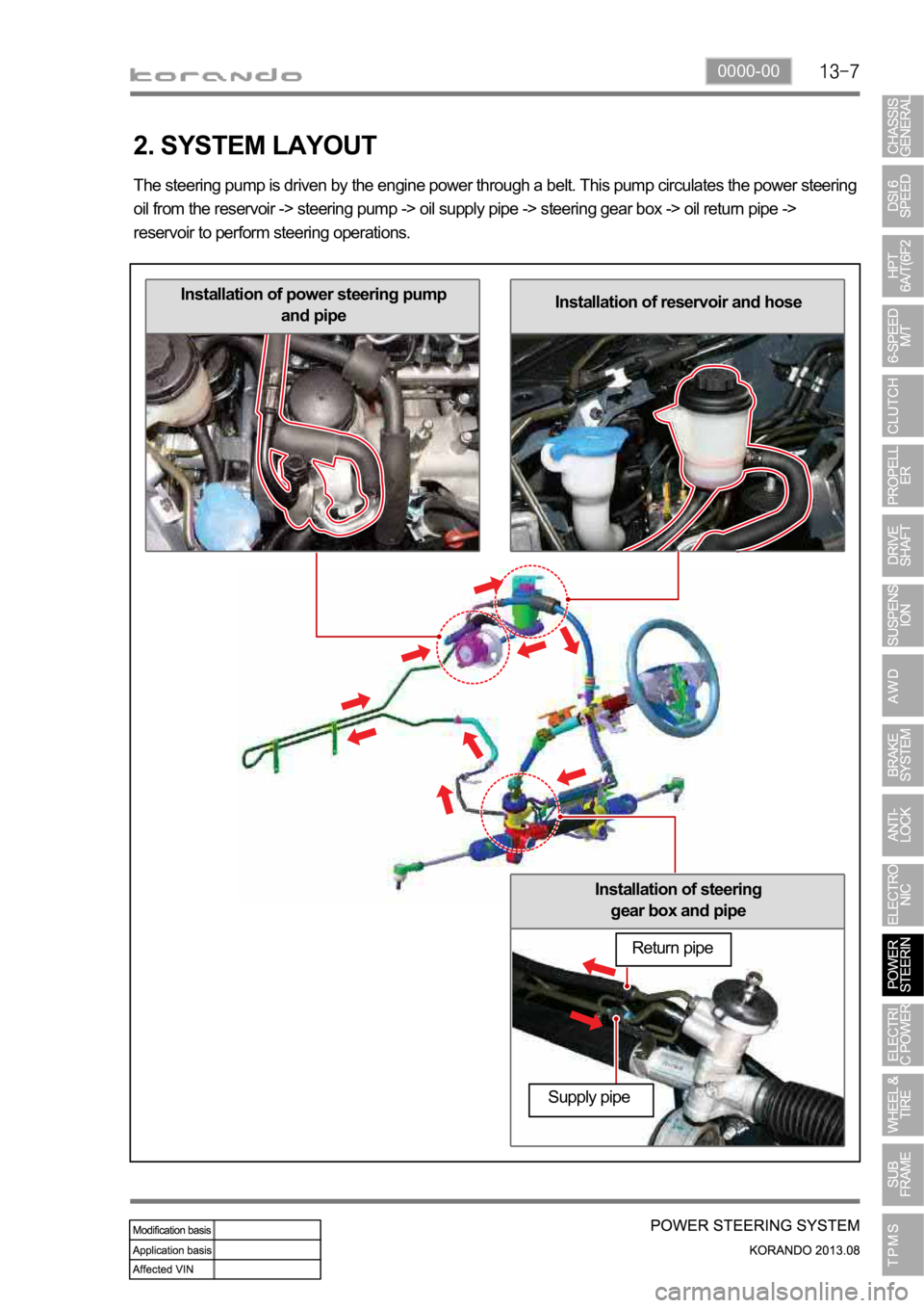
Installation of steering
gear box and pipe
Installation of reservoir and hoseInstallation of power steering pump
and pipe
2. SYSTEM LAYOUT
The steering pump is driven by the engine power through a belt. This pump circulates the power steering
oil from the reservoir -> steering pump -> oil supply pipe -> steering gear box -> oil return pipe ->
reservoir to perform steering operations.
Return pipe
Supply pipe
Page 1153 of 1336
Hydraulic power steering Electric power steering
1. OVERVIEW
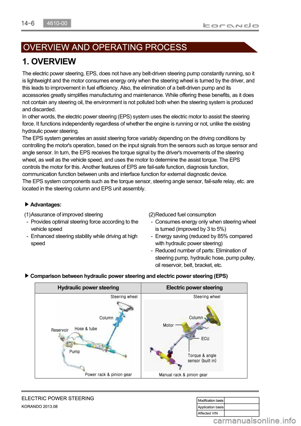
The electric power steering, EPS, does not have any belt-driven steering pump constantly running, so it
is lightweight and the motor consumes energy only when the steering wheel is turned by the driver, and
this leads to improvement in fuel efficiency. Also, the elimination of a belt-driven pump and its
accessories greatly simplifies manufacturing and maintenance. While offering these benefits, as it does
not contain any steering oil, the environment is not polluted both when the steering system is produced
and discarded.
In other words, the electric power steering (EPS) system uses the electric motor to assist the steering
force. It functions independently regardless of whether the engine is running or not, unlike the existing
hydraulic power steering.
The EPS system generates an assist steering force variably depending on the driving conditions by
controlling the motor's operation, based on the input signals from the sensors such as torque sensor and
angle sensor. In turn, the EPS receives the torque signal by the driver's movements of the steering
wheel, as well as the vehicle speed, and uses the motor to determine the assist torque. The EPS
controls the motor for this. Another features of EPS are fail-safe function, diagnosis function,
communication function between units and interface function for external diagnostic device.
The EPS system components such as the torque sensor, steering angle sensor, fail-safe relay, etc. are
located in the steering column and EPS unit assembly.
Advantages:
Assurance of improved steering
Provides optimal steering force according to the
vehicle speed
Enhanced steering stability while driving at high
speed (1)
-
-Reduced fuel consumption
Consumes energy only when steering wheel
is turned (improved by 3 to 5%)
Energy saving (reduced by 85% compared
with hydraulic power steering)
Reduced number of parts: Elimination of
steering pump, hydraulic hose, pump pulley,
oil reservoir, belt, bracket, etc. (2)
-
-
-
Comparison between hydraulic power steering and electric power steering (EPS)