coolant capacity SSANGYONG KORANDO 2013 Service Manual
[x] Cancel search | Manufacturer: SSANGYONG, Model Year: 2013, Model line: KORANDO, Model: SSANGYONG KORANDO 2013Pages: 1336, PDF Size: 92.18 MB
Page 298 of 1336
0000-00
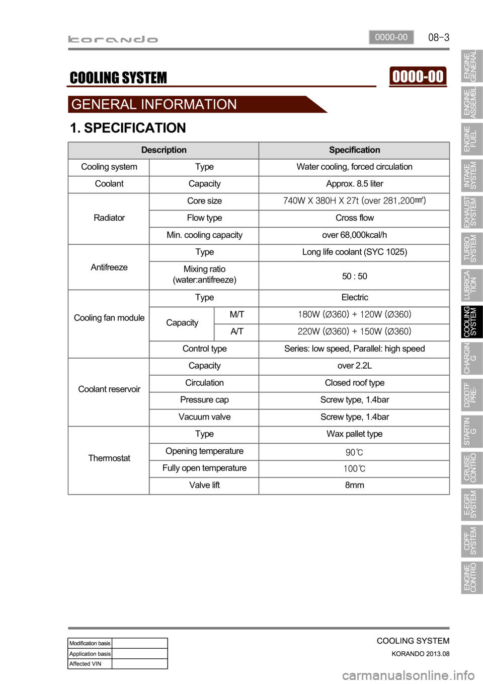
1. SPECIFICATION
Description Specification
Cooling system Type Water cooling, forced circulation
Coolant Capacity Approx. 8.5 liter
RadiatorCore size
Flow type Cross flow
Min. cooling capacity over 68,000kcal/h
AntifreezeType Long life coolant (SYC 1025)
Mixing ratio
(water:antifreeze)50 : 50
Cooling fan moduleType Electric
Control type Series: low speed, Parallel: high speed
Coolant reservoirCapacity over 2.2L
Circulation Closed roof type
Pressure cap Screw type, 1.4bar
Vacuum valve Screw type, 1.4bar
ThermostatType Wax pallet type
Opening temperature
Fully open temperature
Valve lift 8mm
CapacityM/T
A/T
Page 383 of 1336
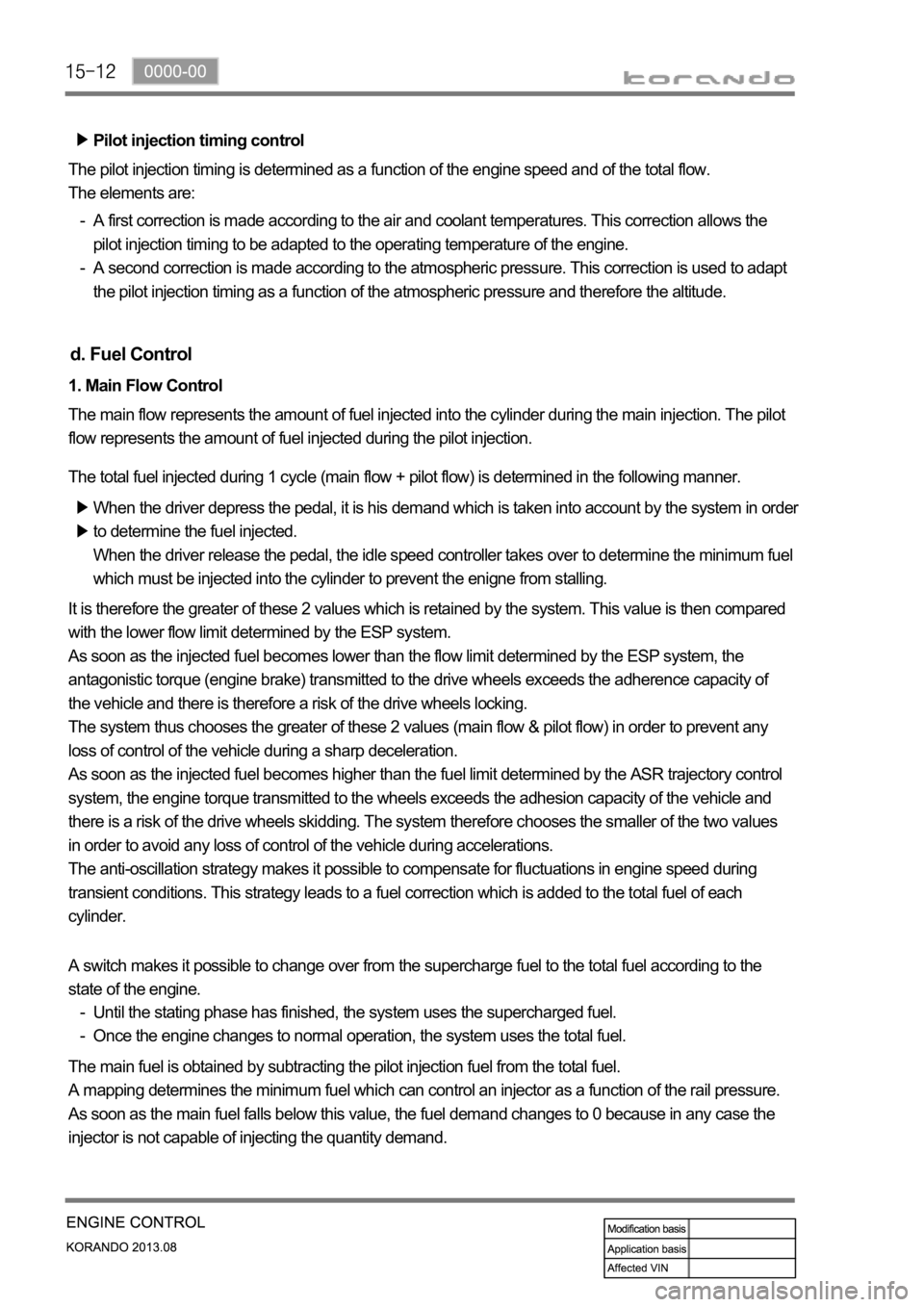
Pilot injection timing control
The pilot injection timing is determined as a function of the engine speed and of the total flow.
The elements are:
A first correction is made according to the air and coolant temperatures. This correction allows the
pilot injection timing to be adapted to the operating temperature of the engine.
A second correction is made according to the atmospheric pressure. This correction is used to adapt
the pilot injection timing as a function of the atmospheric pressure and therefore the altitude. -
-
d. Fuel Control
1. Main Flow Control
The main flow represents the amount of fuel injected into the cylinder during the main injection. The pilot
flow represents the amount of fuel injected during the pilot injection.
The total fuel injected during 1 cycle (main flow + pilot flow) is determined in the following manner.
When the driver depress the pedal, it is his demand which is taken into account by the system in order
to determine the fuel injected.
When the driver release the pedal, the idle speed controller takes over to determine the minimum fuel
which must be injected into the cylinder to prevent the enigne from stalling.
It is therefore the greater of these 2 values which is retained by the system. This value is then compared
with the lower flow limit determined by the ESP system.
As soon as the injected fuel becomes lower than the flow limit determined by the ESP system, the
antagonistic torque (engine brake) transmitted to the drive wheels exceeds the adherence capacity of
the vehicle and there is therefore a risk of the drive wheels locking.
The system thus chooses the greater of these 2 values (main flow & pilot flow) in order to prevent any
loss of control of the vehicle during a sharp deceleration.
As soon as the injected fuel becomes higher than the fuel limit determined by the ASR trajectory control
system, the engine torque transmitted to the wheels exceeds the adhesion capacity of the vehicle and
there is a risk of the drive wheels skidding. The system therefore chooses the smaller of the two values
in order to avoid any loss of control of the vehicle during accelerations.
The anti-oscillation strategy makes it possible to compensate for fluctuations in engine speed during
transient conditions. This strategy leads to a fuel correction which is added to the total fuel of each
cylinder.
The main fuel is obtained by subtracting the pilot injection fuel from the total fuel.
A mapping determines the minimum fuel which can control an injector as a function of the rail pressure.
As soon as the main fuel falls below this value, the fuel demand changes to 0 because in any case the
injector is not capable of injecting the quantity demand. A switch makes it possible to change over from the supercharge fuel to the total fuel according to the
state of the engine.
Until the stating phase has finished, the system uses the supercharged fuel.
Once the engine changes to normal operation, the system uses the total fuel. -
-
Page 408 of 1336
0000-00
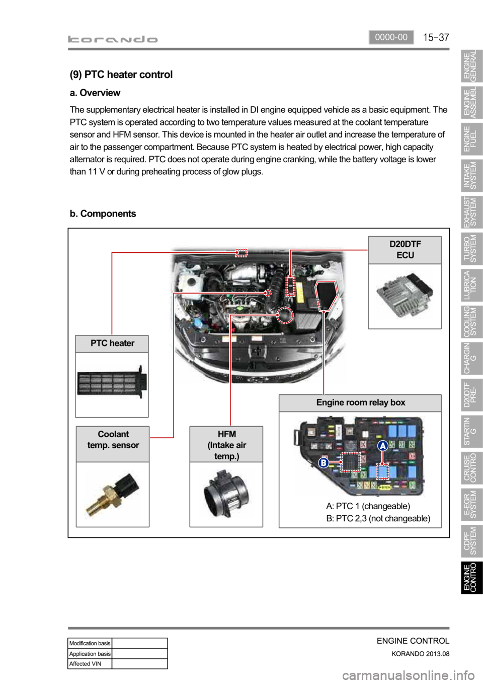
PTC heater
Coolant
temp. sensor
D20DTF
ECU
Engine room relay box
HFM
(Intake air
temp.)
(9) PTC heater control
a. Overview
The supplementary electrical heater is installed in DI engine equipped vehicle as a basic equipment. The
PTC system is operated according to two temperature values measured at the coolant temperature
sensor and HFM sensor. This device is mounted in the heater air outlet and increase the temperature of
air to the passenger compartment. Because PTC system is heated by electrical power, high capacity
alternator is required. PTC does not operate during engine cranking, while the battery voltage is lower
than 11 V or during preheating process of glow plugs.
b. Components
A: PTC 1 (changeable)
B: PTC 2,3 (not changeable)
Page 513 of 1336
2112-01
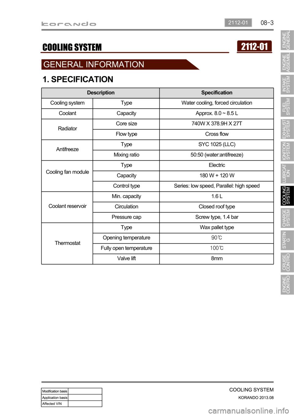
1. SPECIFICATION
Description Specification
Cooling system Type Water cooling, forced circulation
Coolant Capacity Approx. 8.0 ~ 8.5 L
RadiatorCore size 740W X 378.9H X 27T
Flow type Cross flow
AntifreezeType SYC 1025 (LLC)
Mixing ratio 50:50 (water:antifreeze)
Cooling fan moduleType Electric
Capacity 180 W + 120 W
Control type Series: low speed, Parallel: high speed
Coolant reservoirMin. capacity 1.6 L
Circulation Closed roof type
Pressure cap Screw type, 1.4 bar
ThermostatType Wax pallet type
Opening temperature
Fully open temperature
Valve lift 8mm
Page 1221 of 1336
6810-00
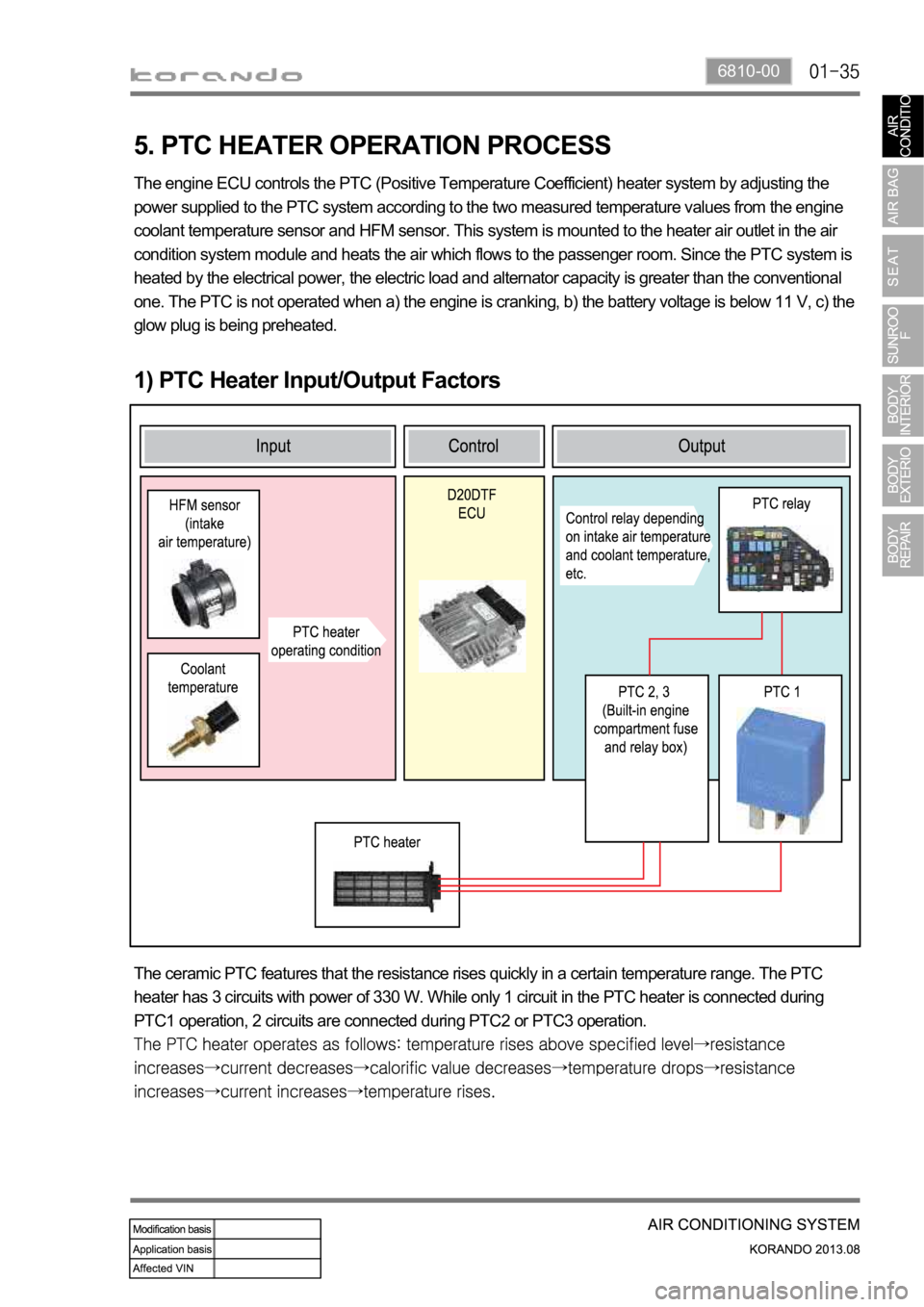
5. PTC HEATER OPERATION PROCESS
1) PTC Heater Input/Output Factors
The engine ECU controls the PTC (Positive Temperature Coefficient) heater system by adjusting the
power supplied to the PTC system according to the two measured temperature values from the engine
coolant temperature sensor and HFM sensor. This system is mounted to the heater air outlet in the air
condition system module and heats the air which flows to the passenger room. Since the PTC system is
heated by the electrical power, the electric load and alternator capacity is greater than the conventional
one. The PTC is not operated when a) the engine is cranking, b) the battery voltage is below 11 V, c) the
glow plug is being preheated.
The ceramic PTC features that the resistance rises quickly in a certain temperature range. The PTC
heater has 3 circuits with power of 330 W. While only 1 circuit in the PTC heater is connected during
PTC1 operation, 2 circuits are connected during PTC2 or PTC3 operation.