lock SSANGYONG KORANDO 2013 Owner's Guide
[x] Cancel search | Manufacturer: SSANGYONG, Model Year: 2013, Model line: KORANDO, Model: SSANGYONG KORANDO 2013Pages: 1336, PDF Size: 92.18 MB
Page 471 of 1336
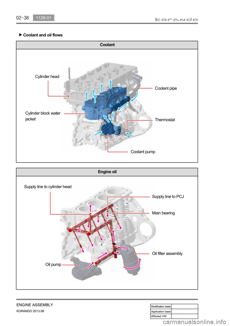
Engine oil
Coolant
Coolant and oil flows
Cylinder head
Cylinder block water
jacket
Coolant pumpCoolant pipe
Thermostat
Supply line to cylinder head
Oil pumpSupply line to PCJ
Main bearing
Oil filter assembly
Page 508 of 1336
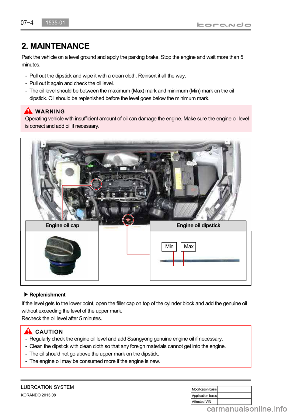
2. MAINTENANCE
Park the vehicle on a level ground and apply the parking brake. Stop the engine and wait more than 5
minutes.
Pull out the dipstick and wipe it with a clean cloth. Reinsert it all the way.
Pull out it again and check the oil level.
The oil level should be between the maximum (Max) mark and minimum (Min) mark on the oil
dipstick. Oil should be replenished before the level goes below the minimum mark. -
-
-
Engine oil dipstickEngine oil cap
Max Min
Replenishment
If the level gets to the lower point, open the filler cap on top of the cylinder block and add the genuine oil
without exceeding the level of the upper mark.
Recheck the oil level after 5 minutes.Operating vehicle with insufficient amount of oil can damage the engine. Make sure the engine oil level
is correct and add oil if necessary.
Regularly check the engine oil level and add Ssangyong genuine engine oil if necessary.
Clean the dipstick with clean cloth so that any foreign materials cannot get into the engine.
The oil should not go above the upper mark on the dipstick.
The engine oil may be consumed more if the engine is new. -
-
-
-
Page 512 of 1336

1) Operation Flow
3. OPERATING PROCESS
CVVT
Cam journal
bearing
Main oil gallery
in cylinder block
Oil pressure
switch
Oil filter assembly
Oil supply Oil pump Main journal bearingChain
tensioner
Oil jet
Page 514 of 1336
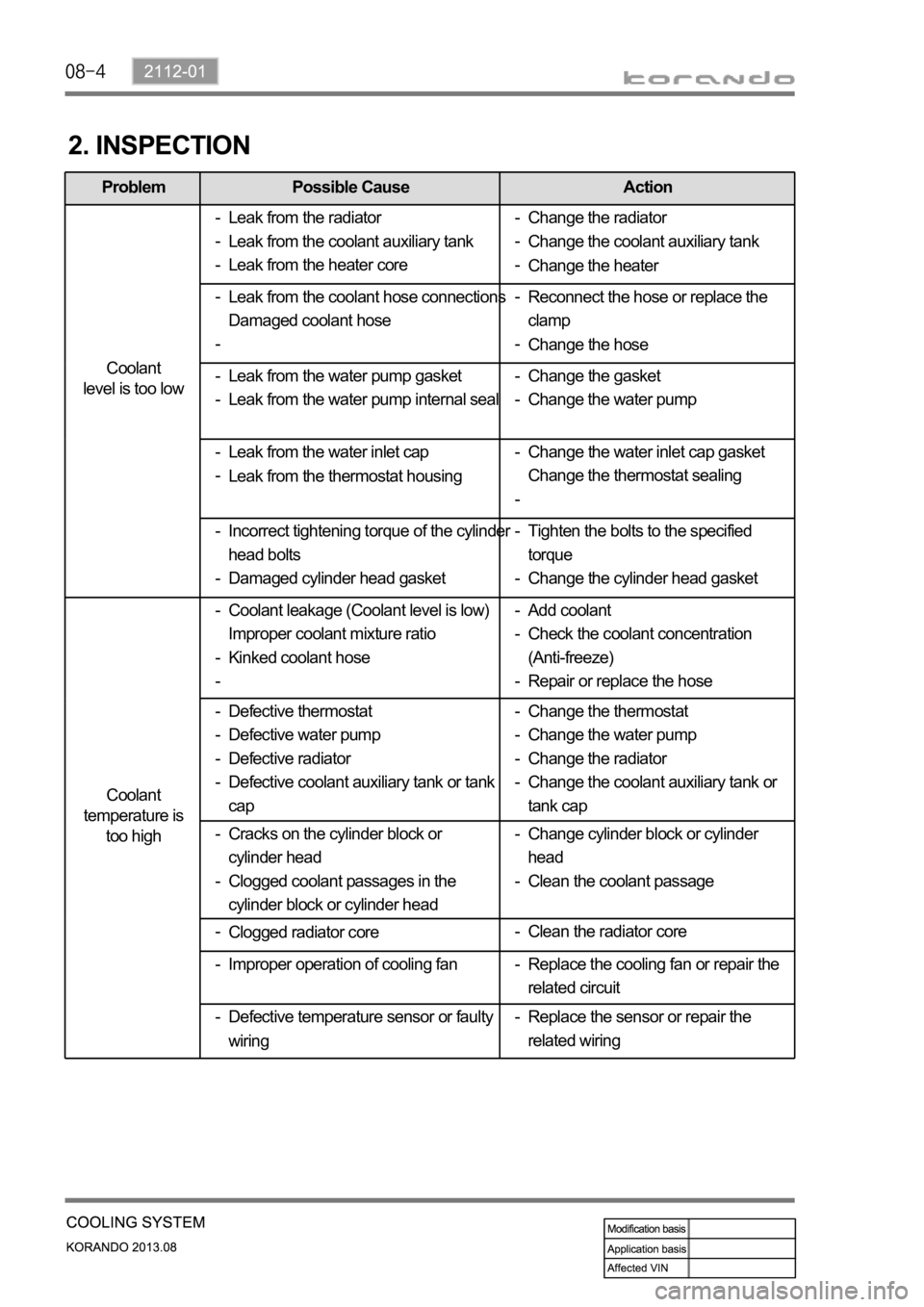
Problem Possible Cause Action
Coolant
level is too low
Coolant
temperature is
too high
2. INSPECTION
Leak from the radiator
Leak from the coolant auxiliary tank
Leak from the heater core -
-
-
Leak from the water inlet cap
Leak from the thermostat housing -
-Reconnect the hose or replace the
clamp
Change the hose -
- Leak from the coolant hose connections
Damaged coolant hose -
-
Change the gasket
Change the water pump -
- Leak from the water pump gasket
Leak from the water pump internal seal -
-
Tighten the bolts to the specified
torque
Change the cylinder head gasket -
- Incorrect tightening torque of the cylinder
head bolts
Damaged cylinder head gasket -
-Change the water inlet cap gasket
Change the thermostat sealing -
-
Coolant leakage (Coolant level is low)
Improper coolant mixture ratio
Kinked coolant hose -
-
-Add coolant
Check the coolant concentration
(Anti-freeze)
Repair or replace the hose -
-
-
Defective thermostat
Defective water pump
Defective radiator
Defective coolant auxiliary tank or tank
cap -
-
-
-Change the thermostat
Change the water pump
Change the radiator
Change the coolant auxiliary tank or
tank cap -
-
-
-Change the radiator
Change the coolant auxiliary tank
Change the heater -
-
-
Cracks on the cylinder block or
cylinder head
Clogged coolant passages in the
cylinder block or cylinder head -
-Change cylinder block or cylinder
head
Clean the coolant passage -
-
Clogged radiator core -
Replace the sensor or repair the
related wiring - Improper operation of cooling fan -Clean the radiator core -
Defective temperature sensor or faulty
wiring -Replace the cooling fan or repair the
related circuit -
Page 533 of 1336
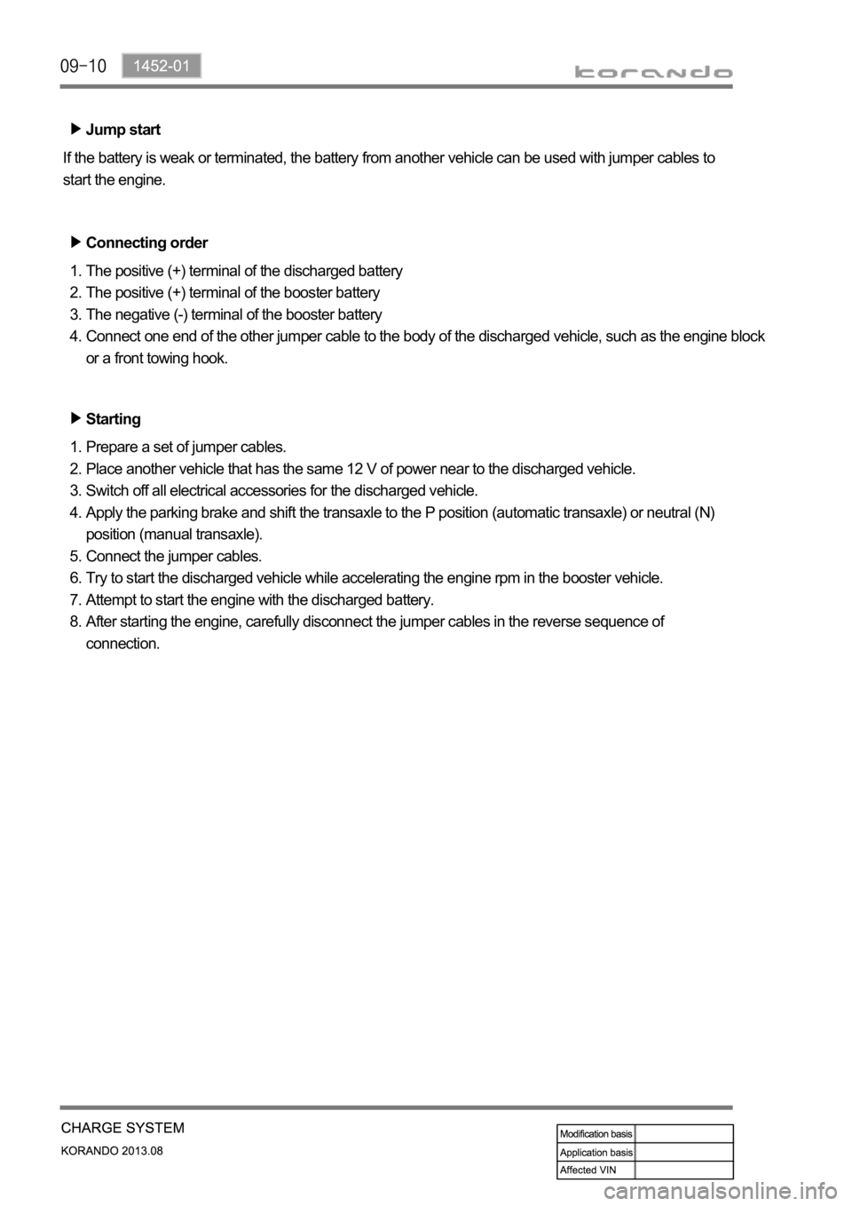
Jump start
If the battery is weak or terminated, the battery from another vehicle can be used with jumper cables to
start the engine.
Connecting order
The positive (+) terminal of the discharged battery
The positive (+) terminal of the booster battery
The negative (-) terminal of the booster battery
Connect one end of the other jumper cable to the body of the discharged vehicle, such as the engine block
or a front towing hook. 1.
2.
3.
4.
Starting
Prepare a set of jumper cables.
Place another vehicle that has the same 12 V of power near to the discharged vehicle.
Switch off all electrical accessories for the discharged vehicle.
Apply the parking brake and shift the transaxle to the P position (automatic transaxle) or neutral (N)
position (manual transaxle).
Connect the jumper cables.
Try to start the discharged vehicle while accelerating the engine rpm in the booster vehicle.
Attempt to start the engine with the discharged battery.
After starting the engine, carefully disconnect the jumper cables in the reverse sequence of
connection. 1.
2.
3.
4.
5.
6.
7.
8.
Page 539 of 1336
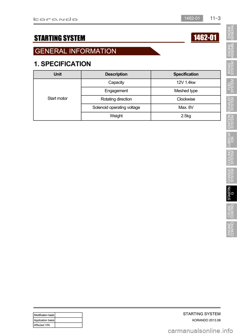
1462-01
1. SPECIFICATION
Unit Description Specification
Start motorCapacity 12V 1.4kw
Engagement Meshed type
Rotating direction Clockwise
Solenoid operating voltage Max. 8V
Weight 2.5kg
Page 572 of 1336
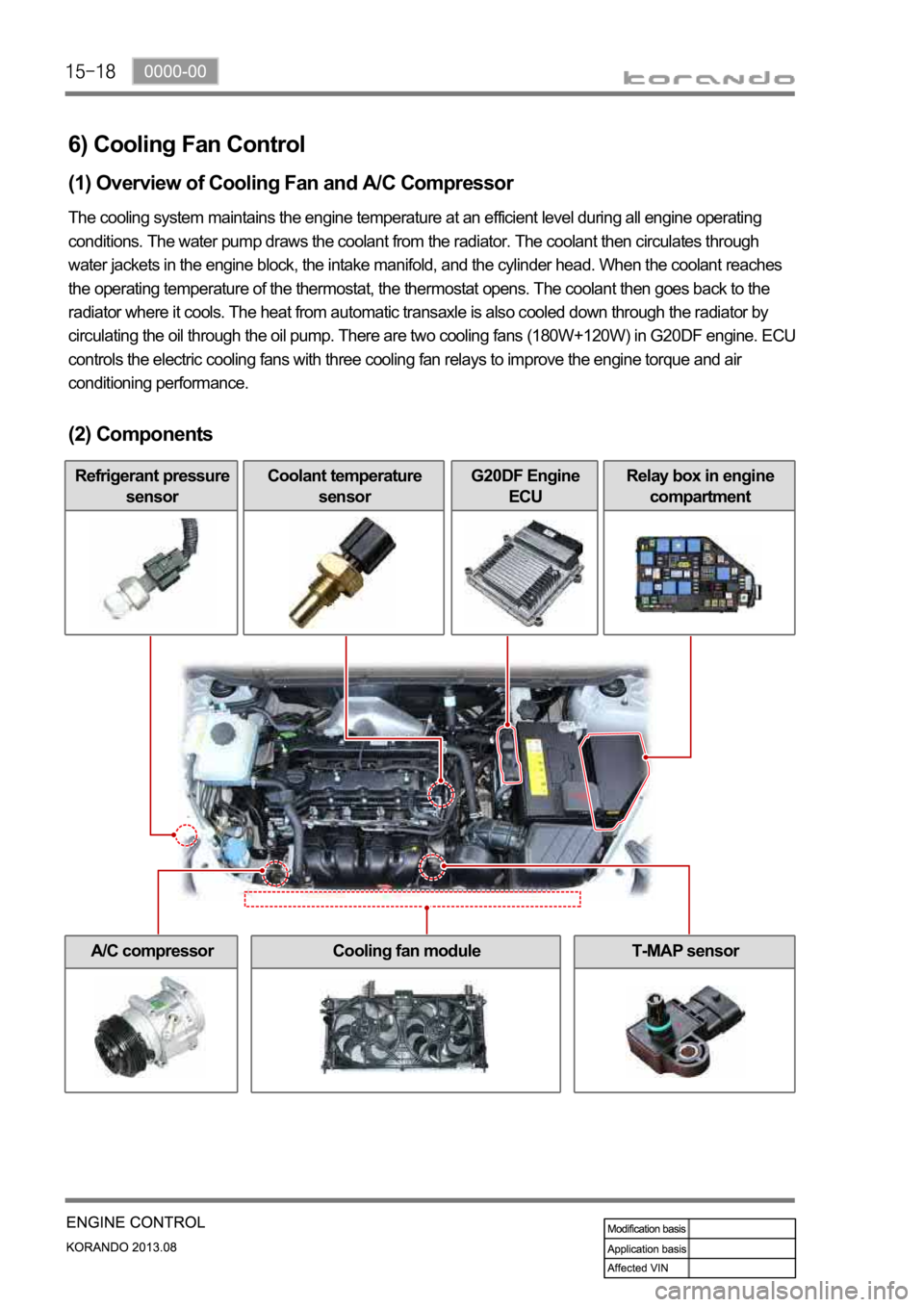
6) Cooling Fan Control
(1) Overview of Cooling Fan and A/C Compressor
The cooling system maintains the engine temperature at an efficient level during all engine operating
conditions. The water pump draws the coolant from the radiator. The coolant then circulates through
water jackets in the engine block, the intake manifold, and the cylinder head. When the coolant reaches
the operating temperature of the thermostat, the thermostat opens. The coolant then goes back to the
radiator where it cools. The heat from automatic transaxle is also cooled down through the radiator by
circulating the oil through the oil pump. There are two cooling fans (180W+120W) in G20DF engine. ECU
controls the electric cooling fans with three cooling fan relays to improve the engine torque and air
conditioning performance.
(2) Components
Refrigerant pressure
sensorCoolant temperature
sensorG20DF Engine
ECURelay box in engine
compartment
A/C compressorCooling fan moduleT-MAP sensor
Page 581 of 1336

2) The chassis number
(KPTA0B1SSAP012345) is stamped on the righ
t
side in the engine compartment (passenger
side).
3) The certification label is affixed on the bottom
of driver side B-pillar. (30 psi)
1) The engine number (671 950 0 2 5000001) is
stamped on the lower area of cylinder block in
exhaust manifold side.
2) Identifications
Page 630 of 1336

Make sure a connector is connected
securely. Loose connection results in
malfunction. -
When disconnecting a connector equipped with
a lock, press it down to the direction in the below
figure. -
When checking voltage or continuity of the
connector terminal with a circuit tester, connect
the tester probe to the terminal at the harness
side. For a sealed type connector, connect the
probe to the terminal through the hole in the
rubber cap of the wiring. Take care not to
damage the insulation of the wires. Insert the
probe until it contacts the terminal completely. -
When inspecting the airbag system, make sure to use a diagnostic device, not a circuit tester.
Page 635 of 1336
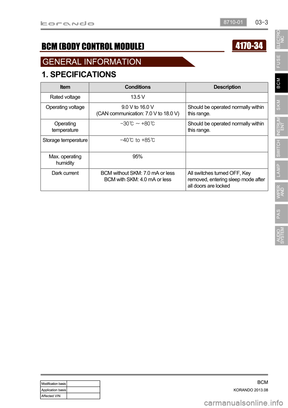
8710-01
1. SPECIFICATIONS
Item Conditions Description
Rated voltage 13.5 V
Operating voltage 9.0 V to 16.0 V
(CAN communication: 7.0 V to 18.0 V)Should be operated normally within
this range.
Operating
temperature
Should be operated normally within
this range.
Storage temperature
Max. operating
humidity95%
Dark current BCM without SKM: 7.0 mA or less
BCM with SKM: 4.0 mA or lessAll switches turned OFF, Key
removed, entering sleep mode after
all doors are locked