torque SSANGYONG KORANDO 2013 Owner's Guide
[x] Cancel search | Manufacturer: SSANGYONG, Model Year: 2013, Model line: KORANDO, Model: SSANGYONG KORANDO 2013Pages: 1336, PDF Size: 92.18 MB
Page 462 of 1336
1130-13
3) Features of DMF
Reduced vibration noise from the powertrain by blocking the torsional vibrations
Enhanced vehicle silence and riding comforts: reduced engine torque fluctuation
Reduced shifting shocks
Smooth acceleration and deceleration -
-
-
-
4) Advantages of DMF
Improved torque response by using 2-stage type spring: Strengthens the torque response in all
ranges (low, medium, and high speed) by applying respective spring constant at each
range.
Stable revolution of the primary and secondary wheel by using planetary gear: Works as auxiliary
damper against spring changes
Less heat generation due to no direct friction against spring surface: Plastic material is covered on the
spring outer surface
Increased durability by using plastic bushing (extends the lifetime of grease) -
-
-
-
Page 514 of 1336
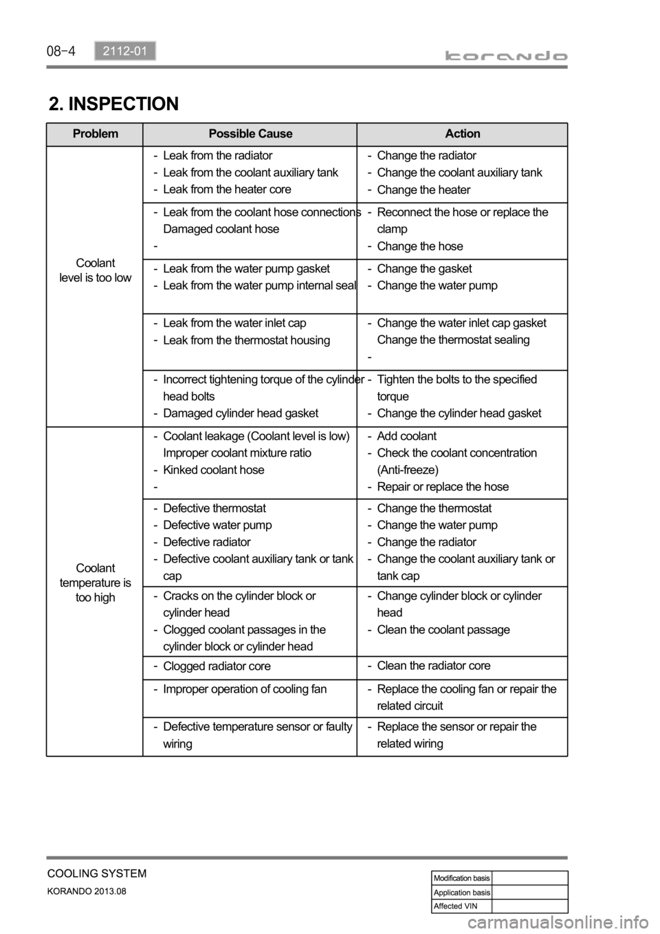
Problem Possible Cause Action
Coolant
level is too low
Coolant
temperature is
too high
2. INSPECTION
Leak from the radiator
Leak from the coolant auxiliary tank
Leak from the heater core -
-
-
Leak from the water inlet cap
Leak from the thermostat housing -
-Reconnect the hose or replace the
clamp
Change the hose -
- Leak from the coolant hose connections
Damaged coolant hose -
-
Change the gasket
Change the water pump -
- Leak from the water pump gasket
Leak from the water pump internal seal -
-
Tighten the bolts to the specified
torque
Change the cylinder head gasket -
- Incorrect tightening torque of the cylinder
head bolts
Damaged cylinder head gasket -
-Change the water inlet cap gasket
Change the thermostat sealing -
-
Coolant leakage (Coolant level is low)
Improper coolant mixture ratio
Kinked coolant hose -
-
-Add coolant
Check the coolant concentration
(Anti-freeze)
Repair or replace the hose -
-
-
Defective thermostat
Defective water pump
Defective radiator
Defective coolant auxiliary tank or tank
cap -
-
-
-Change the thermostat
Change the water pump
Change the radiator
Change the coolant auxiliary tank or
tank cap -
-
-
-Change the radiator
Change the coolant auxiliary tank
Change the heater -
-
-
Cracks on the cylinder block or
cylinder head
Clogged coolant passages in the
cylinder block or cylinder head -
-Change cylinder block or cylinder
head
Clean the coolant passage -
-
Clogged radiator core -
Replace the sensor or repair the
related wiring - Improper operation of cooling fan -Clean the radiator core -
Defective temperature sensor or faulty
wiring -Replace the cooling fan or repair the
related circuit -
Page 557 of 1336
1490-00
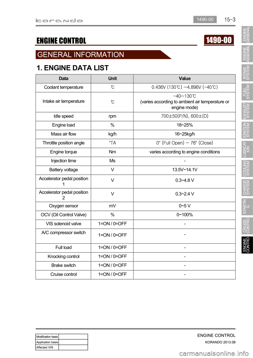
1. ENGINE DATA LIST
Data Unit Value
Coolant temperature
Intake air temperature(varies according to ambient air temperature or
engine mode)
Idle speed rpm
Engine load % 18~25%
Mass air flow kg/h 16~25kg/h
Throttle position angle
Engine torque Nm varies according to engine conditions
Injection time Ms -
Battery voltage V 13.5V~14.1V
Accelerator pedal position
1V 0.3~4.8 V
Accelerator pedal position
2V 0.3~2.4 V
Oxygen sensor mV 0~5 V
OCV (Oil Control Valve) % 0~100%
VIS solenoid valve 1=ON / 0=OFF -
A/C compressor switch
1=ON / 0=OFF-
Full load 1=ON / 0=OFF -
Knocking control 1=ON / 0=OFF -
Brake switch 1=ON / 0=OFF -
Cruise control 1=ON / 0=OFF -
Page 569 of 1336
0000-00
(4) Features
Determines the ignition timing according to input signal
The ECU always analyzes the following elements when determining the ignition timing. 1.
Crankshaft position sensor
Camshaft position sensor
Coolant temperature sensor
Intake air temperature/air mass -
-
-
-
Warm-up of catalytic converter
The ignition timing is retarded for about 20 seconds to operate the catalytic converter according to the
operating temperature under the following conditions: 2.
The idle speed is increased by the idle speed control to help warming up of the catalytic converter -
-
Idle speed control
The ignition timing control can be performed faster than the control through the throttle valve.
Fuel cut-off in deceleration
The ignition timing is retarded temporarily to prevent abrupt increase of the torque when the
combustion is restarted.
Intake air temperature/coolant temperature
The ignition timing is retarded to prevent knocking if the intake air temperature or coolant temperature
is high. The ignition timing is retarded in the following cases. 3.
4.
5.
-
-
The ignition timing retard for intake air temperature and for coolant temperature is added up for
correction.
ESP/ASR control mode
The ignition timing is retarded to reduce engine torque as fast as possible under the ESP/ASR
control mode.
Knocking control
If knocking occurs in the cylinder, the ignition angle of the corresponding cylinder is retarded. The
6.
7.
Page 572 of 1336
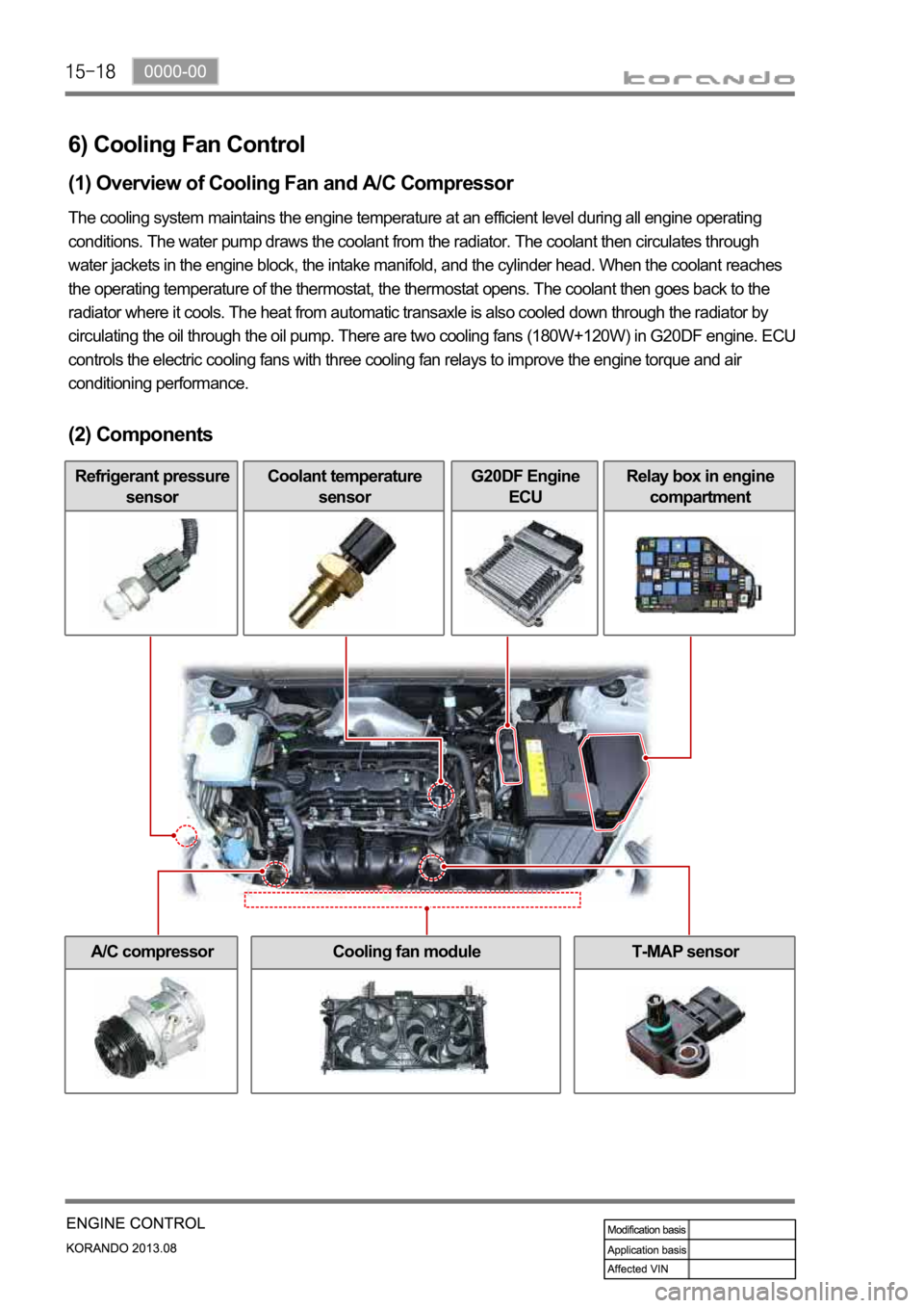
6) Cooling Fan Control
(1) Overview of Cooling Fan and A/C Compressor
The cooling system maintains the engine temperature at an efficient level during all engine operating
conditions. The water pump draws the coolant from the radiator. The coolant then circulates through
water jackets in the engine block, the intake manifold, and the cylinder head. When the coolant reaches
the operating temperature of the thermostat, the thermostat opens. The coolant then goes back to the
radiator where it cools. The heat from automatic transaxle is also cooled down through the radiator by
circulating the oil through the oil pump. There are two cooling fans (180W+120W) in G20DF engine. ECU
controls the electric cooling fans with three cooling fan relays to improve the engine torque and air
conditioning performance.
(2) Components
Refrigerant pressure
sensorCoolant temperature
sensorG20DF Engine
ECURelay box in engine
compartment
A/C compressorCooling fan moduleT-MAP sensor
Page 599 of 1336

0000-00
3. BASIC INSPECTION
1) Battery Terminal
Make sure the terminal connections are
securely tightened. If the terminals are
corroded, clean them or replace the battery. -
* Cleaning
Remove the corrosion or dirt with a wire brush
or sand paper, and then wash out with
lukewarm soapy water.
2) Measuring the Voltage Drop
Measuring at battery terminal
Measure the voltage between battery
terminal (+. -) and wiring clamp. -
Specified valuebelow 0.3V
If the terminals are corroded, clean and
retightening them. If the specified tightening
torque cannot be kept, replace the clamp.
Terminal (+)
Terminal (-)
Terminal (+): 4 ~ 5 Nm
Page 864 of 1336
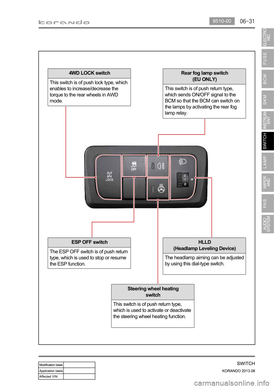
8510-00
4WD LOCK switch
This switch is of push lock type, which
enables to increase/decrease the
torque to the rear wheels in AWD
mode.
Steering wheel heating
switch
This switch is of push return type,
which is used to activate or deactivate
the steering wheel heating function.
ESP OFF switch
The ESP OFF switch is of push return
type, which is used to stop or resume
the ESP function.
4WD LOCK switch
This switch is of push lock type, which
enables to increase/decrease the
torque to the rear wheels in AWD
mode.
HLLD
(Headlamp Leveling Device)
The headlamp aiming can be adjusted
by using this dial-type switch.
Rear fog lamp switch
(EU ONLY)
This switch is of push return type,
which sends ON/OFF signal to the
BCM so that the BCM can switch on
the lamps by activating the rear fog
lamp relay.
Page 984 of 1336
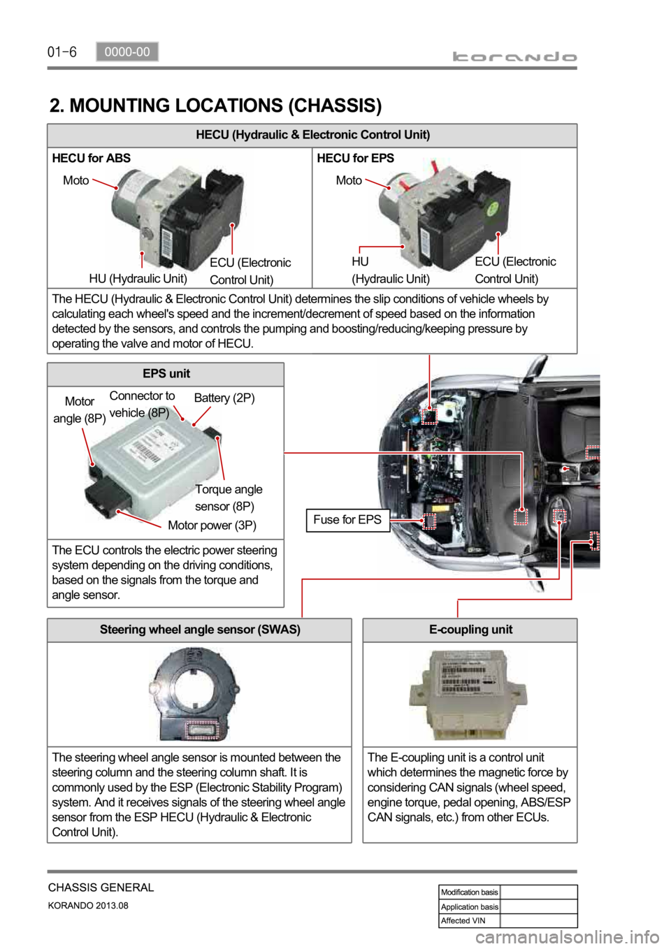
HECU (Hydraulic & Electronic Control Unit)
HECU for ABS HECU for EPS
The HECU (Hydraulic & Electronic Control Unit) determines the slip conditions of vehicle wheels by
calculating each wheel's speed and the increment/decrement of speed based on the information
detected by the sensors, and controls the pumping and boosting/reducing/keeping pressure by
operating the valve and motor of HECU.
2. MOUNTING LOCATIONS (CHASSIS)
Moto
HU (Hydraulic Unit) ECU (Electronic
Control Unit) Moto
HU
(Hydraulic Unit) ECU (Electronic
Control Unit)
Motor
angle (8P)
Motor power (3P)Torque angle
sensor (8P) Battery (2P) Connector to
vehicle (8P)
Fuse for EPS
Steering wheel angle sensor (SWAS)
The steering wheel angle sensor is mounted between the
steering column and the steering column shaft. It is
commonly used by the ESP (Electronic Stability Program)
system. And it receives signals of the steering wheel angle
sensor from the ESP HECU (Hydraulic & Electronic
Control Unit).
EPS unit
The ECU controls the electric power steering
system depending on the driving conditions,
based on the signals from the torque and
angle sensor.
E-coupling unit
The E-coupling unit is a control unit
which determines the magnetic force by
considering CAN signals (wheel speed,
engine torque, pedal opening, ABS/ESP
CAN signals, etc.) from other ECUs.
Page 986 of 1336
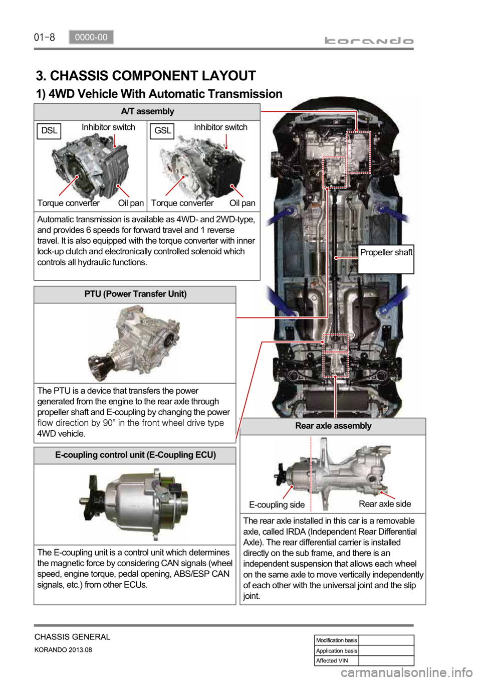
A/T assembly
Automatic transmission is available as 4WD- and 2WD-type,
and provides 6 speeds for forward travel and 1 reverse
travel. It is also equipped with the torque converter with inner
lock-up clutch and electronically controlled solenoid which
controls all hydraulic functions.
3. CHASSIS COMPONENT LAYOUT
PTU (Power Transfer Unit)
The PTU is a device that transfers the power
generated from the engine to the rear axle through
propeller shaft and E-coupling by changing the power
4WD vehicle.Rear axle assembly
The rear axle installed in this car is a removable
axle, called IRDA (Independent Rear Differential
Axle). The rear differential carrier is installed
directly on the sub frame, and there is an
independent suspension that allows each wheel
on the same axle to move vertically independentl
y
of each other with the universal joint and the slip
joint.
E-coupling control unit (E-Coupling ECU)
The E-coupling unit is a control unit which determines
the magnetic force by considering CAN signals (wheel
speed, engine torque, pedal opening, ABS/ESP CAN
signals, etc.) from other ECUs.
Inhibitor switch
Torque converter Oil pan
E-coupling sideRear axle side
Propeller shaft
1) 4WD Vehicle With Automatic Transmission
GSLDSLInhibitor switch
Torque converter Oil pan
Page 987 of 1336

0000-00
M6LF1 manual transmission
M6LF1 manual transmission is a model modified from the
one that used in other vehicle so that it can be applied to FF
(Front engine-Front wheel driving) type vehicle, and has an
axle in one piece. The engine torque and gear ratio of this
transmission have been optimized to maximize driving
performance. It provides 6 speeds for forward travel and 1
reverse travel.
Clutch assembly
M6LF1 manual transmission is a model modified from the
one that used in other vehicle so that it can be applied to FF
(Front engine-Front wheel driving) type vehicle, and has an
axle in one piece. The engine torque and gear ratio of this
transmission have been optimized to maximize driving
performance. It provides 6 speeds for forward travel and 1
reverse travel.
The 2WD vehicle with manual transmission is a front wheel drive type vehicle that doesn't have PTU,
propeller shaft, E-coupling and rear axle which are applied to 4WD vehicle. Its under structure is very
simple.
Manual gear selector lever
Transmission sideControl shaft assembly
Transaxle side
Concentric slave assembly
Pressure plate
2) 2WD Vehicle With Manual Transmission
Clutch disc