torque SSANGYONG KORANDO 2013 Owner's Manual
[x] Cancel search | Manufacturer: SSANGYONG, Model Year: 2013, Model line: KORANDO, Model: SSANGYONG KORANDO 2013Pages: 1336, PDF Size: 92.18 MB
Page 405 of 1336
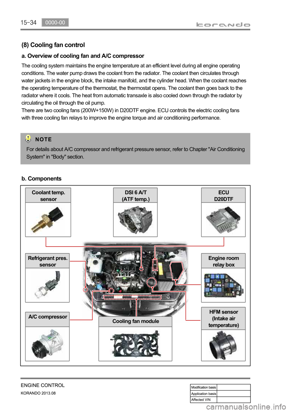
Coolant temp.
sensor
Refrigerant pres.
sensor
A/C compressor
ECU
D20DTFDSI 6 A/T
(ATF temp.)
Cooling fan module
HFM sensor
(Intake air
temperature)
Engine room
relay box
(8) Cooling fan control
a. Overview of cooling fan and A/C compressor
The cooling system maintains the engine temperature at an efficient level during all engine operating
conditions. The water pump draws the coolant from the radiator. The coolant then circulates through
water jackets in the engine block, the intake manifold, and the cylinder head. When the coolant reaches
the operating temperature of the thermostat, the thermostat opens. The coolant then goes back to the
radiator where it cools. The heat from automatic transaxle is also cooled down through the radiator by
circulating the oil through the oil pump.
There are two cooling fans (200W+150W) in D20DTF engine. ECU controls the electric cooling fans
with three cooling fan relays to improve the engine torque and air conditioning performance.
For details about A/C compressor and refrigerant pressure sensor, refer to Chapter "Air Conditioning
System" in "Body" section.
b. Components
Page 426 of 1336
0000-00
3) General Instructions
Before lifting up the vehicle with a lift, correctly support the lifting points.
When using a jack, park the vehicle on a level ground and place the wheel chocks under the tires.
Position the jack under the frame and lift up the vehicle and then support with chassis stand before
service work.
Make sure to disconnect the negative (-) cable from the battery to prevent any damage to electric
systems.
If you have to work on vehicle, cover the seats and floor with protection covers to avoid any
damage and contamination.
Brake fluid and anti-freeze can damage the painted surface of body. So carefully handle them
during service work.
To improve the efficiency of service work, use only recommended and specified tools.
Use only Ssangyong genuine spare parts.
Never reuse the cotter pin, gasket, O-ring, oil seal, lock washer and self-locking nut. Replace them
with new ones. If reused, normal functions cannot be maintained.
Store the disassembled parts as a set based on disassembly order and unit.
Pay particular attention not to miss or mix the fasteners.
If necessary, especially for inspection, clean the removed parts completely.
Apply the oil or grease on the running and sliding surfeces before installation. Use the specified
sealant and gasket to prevent leakage if necessary.
Tighten the fasteners to the specified tightening torque.
As a final stage of service work, check if the serviced system is working properly and the problem
has been eliminated clearly. (1)
(2)
(3)
(4)
(5)
(6)
(7)
(8)
(9)
(10)
(11)
(12)
(13)
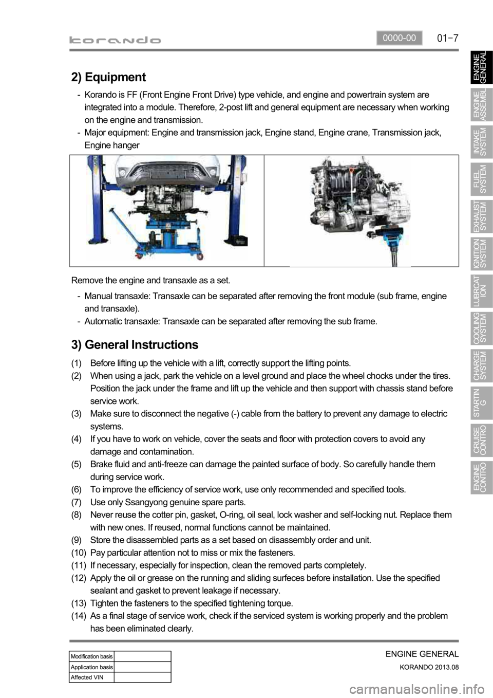
(14) Remove the engine and transaxle as a set.
Manual transaxle: Transaxle can be separated after removing the front module (sub frame, engine
and transaxle).
Automatic transaxle: Transaxle can be separated after removing the sub frame. -
-
2) Equipment
Korando is FF (Front Engine Front Drive) type vehicle, and engine and powertrain system are
integrated into a module. Therefore, 2-post lift and general equipment are necessary when working
on the engine and transmission.
Major equipment: Engine and transmission jack, Engine stand, Engine crane, Transmission jack,
Engine hanger -
-
Page 428 of 1336
0000-00
5) Guidelines on Engine Service
(1) Cautions before service works
Make sure to disconnect the negative (-) cable from the battery to prevent any damage to electric
systems.
Make sure to clean the working area and to prepare the necessary tools before service works.
Always place the ignition switch to OFF position if not required. Otherwise, there could be unexpected
damage to electric devices or personal injuries due to short-circuit.
To prevent the foreign material from entering into the fuel injection system, completely seal the inlets o
f
HP pump, fuel hoses and high pressure pipes.
To remoev the engine, use the dedicated equipments such as engine jack, transmission jack, engine
stand and engine crane. -
-
-
-
-
(2) Engine and accessories
When disassembling the engine, related parts (bolts, gaskets, etc.) should be stored as a set.
Clean the components completely with engine oil before assembling if needed.
Fully drain the engine oil, coolant and fuel from the vehicle and seal the inlets with the plugs before
removing the engine.
All the interference should be eliminated before removing the engine. -
-
-
- To prevent the personal injuries and vehicle damages that can be caused by mistakes during service
and to provide the optimized performance and safety after service works, the service technicials must
keep the basic cautions and service guidelines below. These could be easily forgotten during service
works.
Engine has a lot of precise components. The specified tightening torque and correct procedures should
be kept during service works. And, the working area is always clean and well prepared.
To prevent any damage to electric systems, make sure to disconnect the negative (-) cable from the
battery and place the ignition switch to OFF position before servicing.
Use only the specified parts with same ratings when replacing the electric devices. Check the
grounds and connections for looseness. -
-
(3) Electric devices
Extraordinary care should be taken when servicing the electric systems. Currently, the engine uses a lot
of electric devices. Short circuit and poor contact may cause the low engine performance, incomplete
combustion and other abnormalities.
When working with the fuel or oil systems in enclosed area, always keep the working area well-
ventilated and never allow anybody to smoke.
Gaskets and seals on the fuel and oil systems should be replaced with new ones. All bolts and nuts
should be tightened as specified.
Make sure to check the connections for leak after installation. -
-
-
(4) Fuel and lubrication system
Page 430 of 1336

0000-00
3. STANDARD BOLTS SPECIFICATIONS
Metric bolt strength is embossed on the head of each bolt. The strength of bolt can be classified as
4T, 7T, 8.8T, 10.9T, 11T and 12.9T in general.
Observe standard tightening torque during bolt tightening works and can adjust torque to be proper
within 15 % if necessary. Try not to over max. allowable tightening torque if not required to do so.
Determine extra proper tightening torque if tightens with washer or packing.
If tightens bolts on the below materials, be sure to determine the proper torque. 1)
2)
3)
4)
Aluminum alloy: Tighten to 80 % of above torque table.
Plastics: Tighten to 20 % of above torque table. -
-
Page 437 of 1336
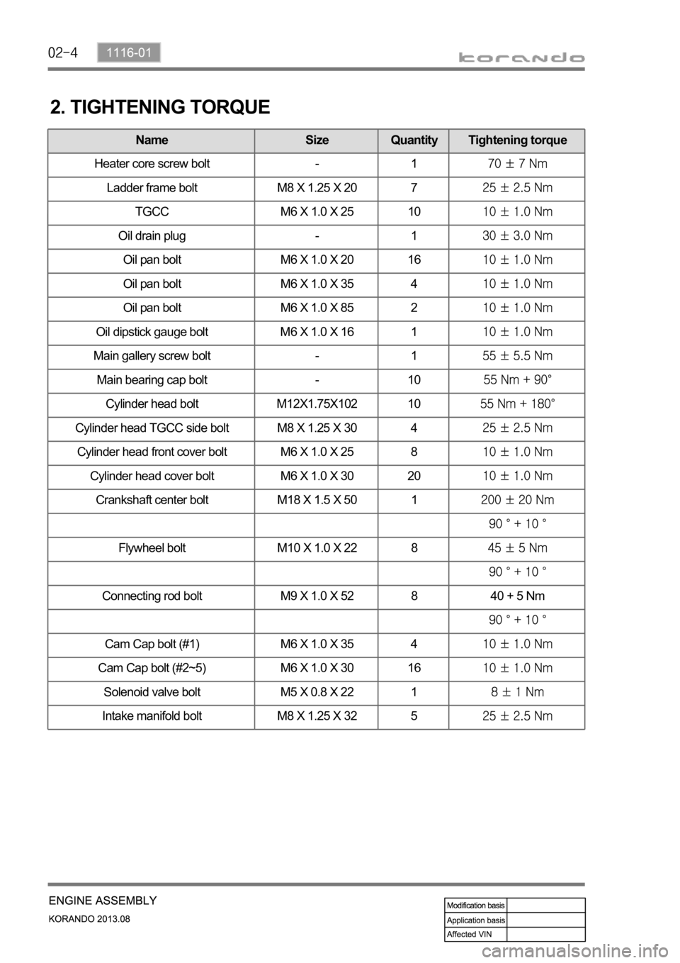
Name Size Quantity Tightening torque
Oil pan bolt M6 X 1.0 X 20 16
Oil pan bolt M6 X 1.0 X 35 4
Oil pan bolt M6 X 1.0 X 85 2
Oil dipstick gauge bolt M6 X 1.0 X 16 1
Camshaft cap M6 X 1.0 X 30 20
Main gallery screw bolt - 1
Main bearing cap bolt - 10
Cylinder head bolt M12X1.75X102 10
Cylinder head TGCC side bolt M8 X 1.25 X 30 4
Cylinder head front cover bolt M6 X 1.0 X 25 8
Cylinder head cover bolt M6 X 1.0 X 30 20
Crankshaft center bolt M18 X 1.5 X 50 1
Flywheel bolt M10 X 1.0 X 22 8
Connecting rod bolt M9 X 1.0 X 52 8 40 + 5 Nm
Cam Cap bolt (#1) M6 X 1.0 X 35 4
Cam Cap bolt (#2~5) M6 X 1.0 X 30 16
Solenoid valve bolt M5 X 0.8 X 22 1
Intake manifold bolt M8 X 1.25 X 32 5
2. TIGHTENING TORQUE
Name Size Quantity Tightening torque
Heater core screw bolt - 1
Ladder frame bolt M8 X 1.25 X 20 7
TGCC M6 X 1.0 X 25 10
Oil drain plug - 1
Oil pan bolt M6 X 1.0 X 20 16
Oil pan bolt M6 X 1.0 X 35 4
Oil pan bolt M6 X 1.0 X 85 2
Oil dipstick gauge bolt M6 X 1.0 X 16 1
Page 438 of 1336
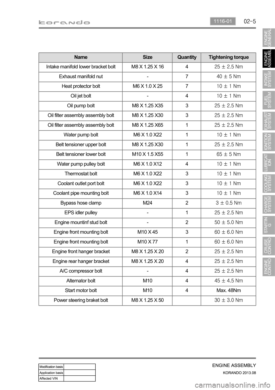
1116-01
Name Size Quantity Tightening torque
Intake manifold lower bracket bolt M8 X 1.25 X 16 4
Exhaust manifold nut - 7
Heat protector bolt M6 X 1.0 X 25 7
Oil jet bolt - 4
Oil pump bolt M8 X 1.25 X35 3
Oil filter assembly assembly bolt M8 X 1.25 X30 3
Oil filter assembly assembly bolt M8 X 1.25 X65 1
Water pump bolt M6 X 1.0 X22 1
Belt tensioner upper bolt M8 X 1.25 X30 1
Belt tensioner lower bolt M10 X 1.5 X55 1
Water pump pulley bolt M6 X 1.0 X12 4
Thermostat bolt M6 X 1.0 X22 3
Coolant outlet port bolt M6 X 1.0 X22 3
Coolant pipe mounting bolt M6 X 1.0 X14 3
Bypass hose clamp M24 2
EPS idler pulley - 1
Engine mountinf stud bolt - 2
Engine front mounting bolt M10 X 45 3
Engine front mounting bolt M10 X 77 1
Engine front hanger bracket M8 X 1.25 X 20 2
Engine rear hanger bracket M8 X 1.25 X 20 4
A/C compressor bolt - 4
Alternator bolt M10 4
Start motor bolt M10 4 Max. 48Nm
Power steering braket bolt M8 X 1.25 X 50
Page 440 of 1336
1116-01
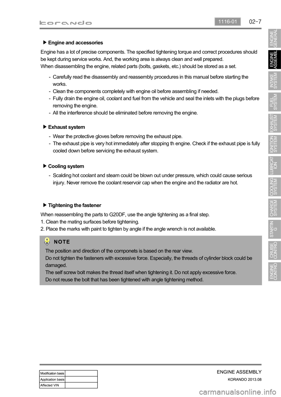
Engine and accessories
Engine has a lot of precise components. The specified tightening torque and correct procedures should
be kept during service works. And, the working area is always clean and well prepared.
When disassembling the engine, related parts (bolts, gaskets, etc.) should be stored as a set.
Carefully read the disassembly and reassembly procedures in this manual before starting the
works.
Clean the components completely with engine oil before assembling if needed.
Fully drain the engine oil, coolant and fuel from the vehicle and seal the inlets with the plugs before
removing the engine.
All the interference should be eliminated before removing the engine. -
-
-
-
Tightening the fastener
When reassembling the parts to G20DF, use the angle tightening as a final step.
1. Clean the mating surfaces before tightening.
2. Place the marks with paint to tighten by angle if the angle wrench is not available. Exhaust system
Wear the protective gloves before removing the exhaust pipe.
The exhaust pipe is very hot immediately after stopping th engine. Check if the exhaust pipe is fully
cooled down before servicing the exhaust system. -
-
Cooling system
Scalding hot coolant and steam could be blown out under pressure, which could cause serious
injury. Never remove the coolant reservoir cap when the engine and the radiator are hot. -
The position and direction of the componets is based on the rear view.
Do not tighten the fasteners with excessive force. Especially, the threads of cylinder block could be
damaged.
The self screw bolt makes the thread itself when tightening it. Do not apply excessive force.
Do not reuse the bolt that has been tightened with angle tightening method.
Page 446 of 1336
1990-01
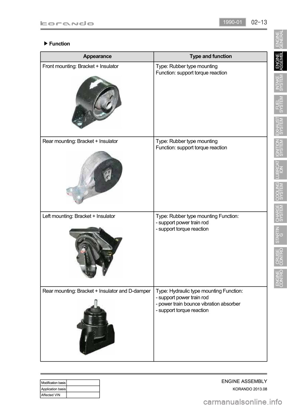
Function
Appearance Type and function
Front mounting: Bracket + Insulator Type: Rubber type mounting
Function: support torque reaction
Rear mounting: Bracket + Insulator Type: Rubber type mounting
Function: support torque reaction
Left mounting: Bracket + Insulator Type: Rubber type mounting Function:
- support power train rod
- support torque reaction
Rear mounting: Bracket + Insulator and D-damper Type: Hydraulic type mounting Function:
- support power train rod
- power train bounce vibration absorber
- support torque reaction
Page 460 of 1336
1130-13
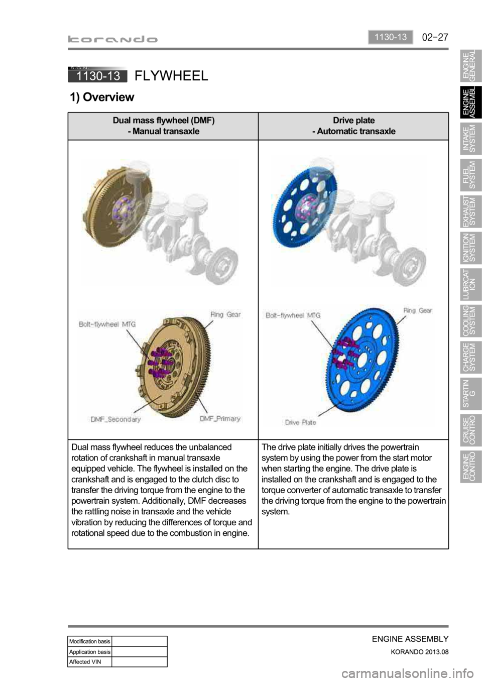
1) Overview
Dual mass flywheel (DMF)
- Manual transaxleDrive plate
- Automatic transaxle
Dual mass flywheel reduces the unbalanced
rotation of crankshaft in manual transaxle
equipped vehicle. The flywheel is installed on the
crankshaft and is engaged to the clutch disc to
transfer the driving torque from the engine to the
powertrain system. Additionally, DMF decreases
the rattling noise in transaxle and the vehicle
vibration by reducing the differences of torque and
rotational speed due to the combustion in engine.The drive plate initially drives the powertrain
system by using the power from the start motor
when starting the engine. The drive plate is
installed on the crankshaft and is engaged to the
torque converter of automatic transaxle to transfer
the driving torque from the engine to the powertrain
system.
Page 461 of 1336
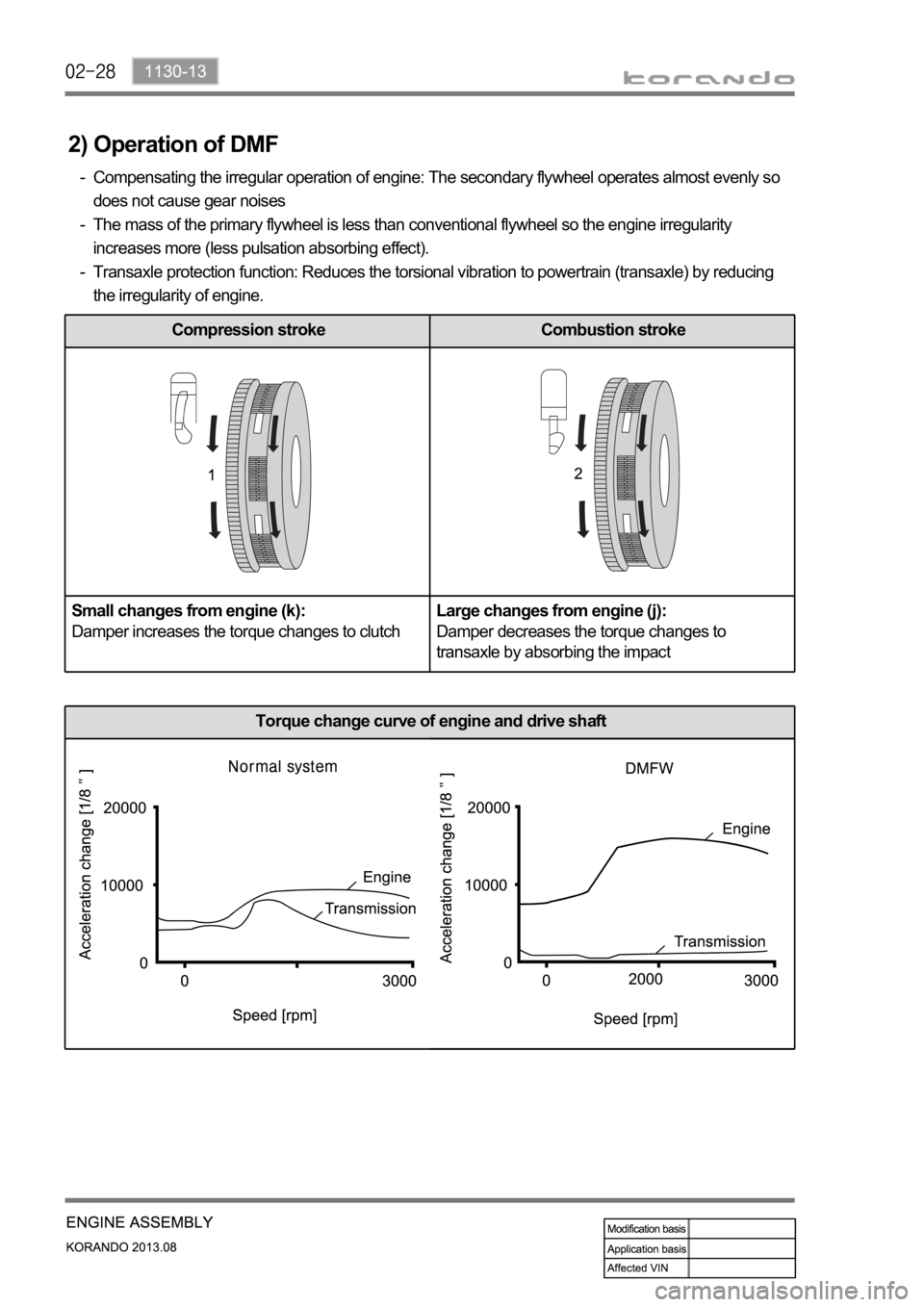
2) Operation of DMF
Compensating the irregular operation of engine: The secondary flywheel operates almost evenly so
does not cause gear noises
The mass of the primary flywheel is less than conventional flywheel so the engine irregularity
increases more (less pulsation absorbing effect).
Transaxle protection function: Reduces the torsional vibration to powertrain (transaxle) by reducing
the irregularity of engine. -
-
-
Compression stroke Combustion stroke
Small changes from engine (k):
Damper increases the torque changes to clutchLarge changes from engine (j):
Damper decreases the torque changes to
transaxle by absorbing the impact
Torque change curve of engine and drive shaft