coolant SSANGYONG KORANDO 2013 Workshop Manual
[x] Cancel search | Manufacturer: SSANGYONG, Model Year: 2013, Model line: KORANDO, Model: SSANGYONG KORANDO 2013Pages: 1336, PDF Size: 92.18 MB
Page 428 of 1336
0000-00
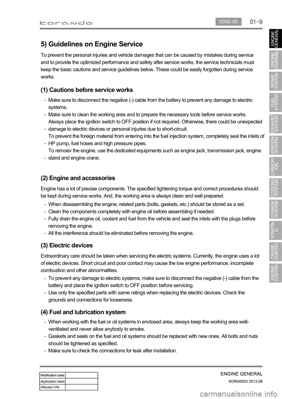
5) Guidelines on Engine Service
(1) Cautions before service works
Make sure to disconnect the negative (-) cable from the battery to prevent any damage to electric
systems.
Make sure to clean the working area and to prepare the necessary tools before service works.
Always place the ignition switch to OFF position if not required. Otherwise, there could be unexpected
damage to electric devices or personal injuries due to short-circuit.
To prevent the foreign material from entering into the fuel injection system, completely seal the inlets o
f
HP pump, fuel hoses and high pressure pipes.
To remoev the engine, use the dedicated equipments such as engine jack, transmission jack, engine
stand and engine crane. -
-
-
-
-
(2) Engine and accessories
When disassembling the engine, related parts (bolts, gaskets, etc.) should be stored as a set.
Clean the components completely with engine oil before assembling if needed.
Fully drain the engine oil, coolant and fuel from the vehicle and seal the inlets with the plugs before
removing the engine.
All the interference should be eliminated before removing the engine. -
-
-
- To prevent the personal injuries and vehicle damages that can be caused by mistakes during service
and to provide the optimized performance and safety after service works, the service technicials must
keep the basic cautions and service guidelines below. These could be easily forgotten during service
works.
Engine has a lot of precise components. The specified tightening torque and correct procedures should
be kept during service works. And, the working area is always clean and well prepared.
To prevent any damage to electric systems, make sure to disconnect the negative (-) cable from the
battery and place the ignition switch to OFF position before servicing.
Use only the specified parts with same ratings when replacing the electric devices. Check the
grounds and connections for looseness. -
-
(3) Electric devices
Extraordinary care should be taken when servicing the electric systems. Currently, the engine uses a lot
of electric devices. Short circuit and poor contact may cause the low engine performance, incomplete
combustion and other abnormalities.
When working with the fuel or oil systems in enclosed area, always keep the working area well-
ventilated and never allow anybody to smoke.
Gaskets and seals on the fuel and oil systems should be replaced with new ones. All bolts and nuts
should be tightened as specified.
Make sure to check the connections for leak after installation. -
-
-
(4) Fuel and lubrication system
Page 438 of 1336
1116-01
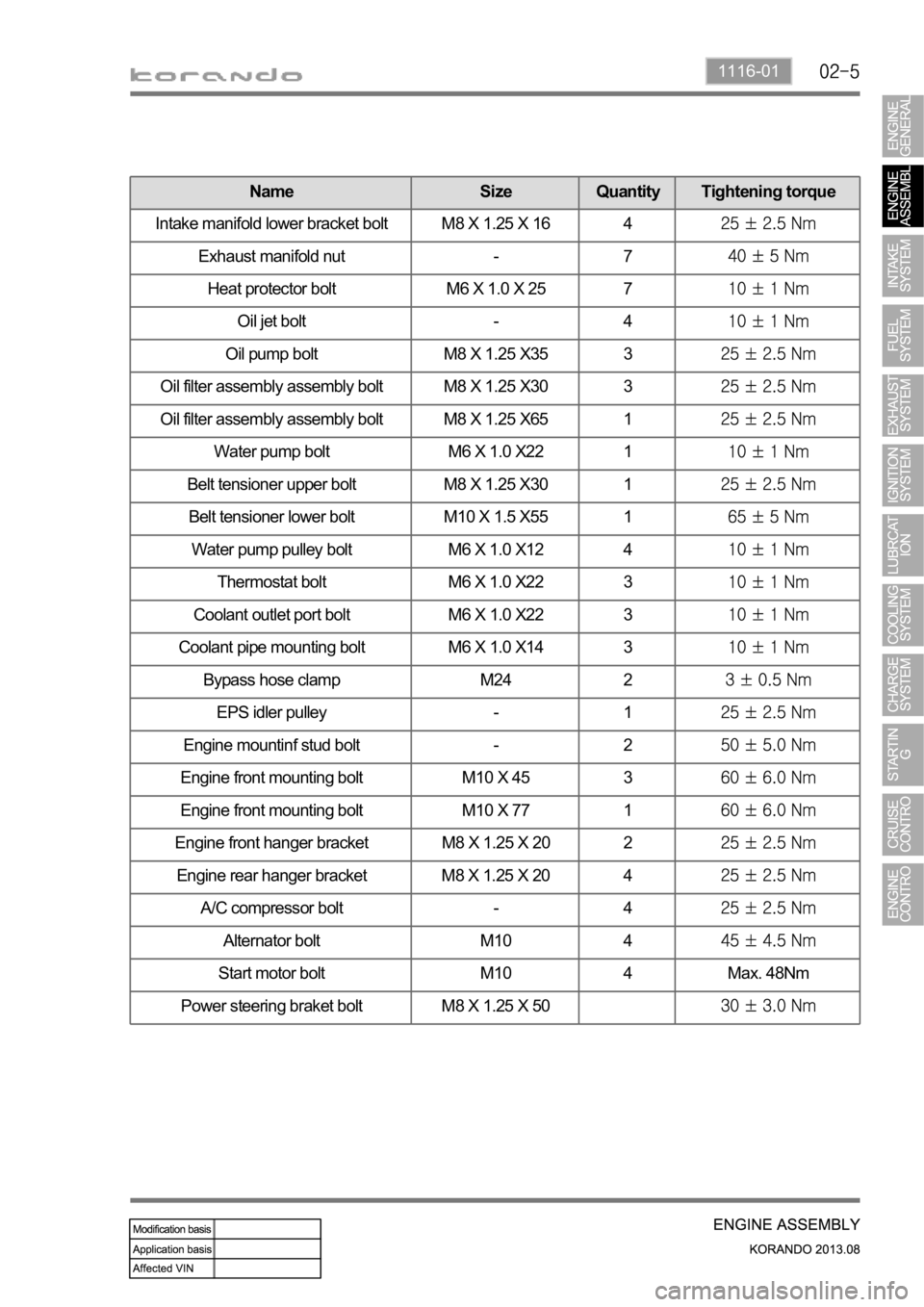
Name Size Quantity Tightening torque
Intake manifold lower bracket bolt M8 X 1.25 X 16 4
Exhaust manifold nut - 7
Heat protector bolt M6 X 1.0 X 25 7
Oil jet bolt - 4
Oil pump bolt M8 X 1.25 X35 3
Oil filter assembly assembly bolt M8 X 1.25 X30 3
Oil filter assembly assembly bolt M8 X 1.25 X65 1
Water pump bolt M6 X 1.0 X22 1
Belt tensioner upper bolt M8 X 1.25 X30 1
Belt tensioner lower bolt M10 X 1.5 X55 1
Water pump pulley bolt M6 X 1.0 X12 4
Thermostat bolt M6 X 1.0 X22 3
Coolant outlet port bolt M6 X 1.0 X22 3
Coolant pipe mounting bolt M6 X 1.0 X14 3
Bypass hose clamp M24 2
EPS idler pulley - 1
Engine mountinf stud bolt - 2
Engine front mounting bolt M10 X 45 3
Engine front mounting bolt M10 X 77 1
Engine front hanger bracket M8 X 1.25 X 20 2
Engine rear hanger bracket M8 X 1.25 X 20 4
A/C compressor bolt - 4
Alternator bolt M10 4
Start motor bolt M10 4 Max. 48Nm
Power steering braket bolt M8 X 1.25 X 50
Page 440 of 1336
1116-01
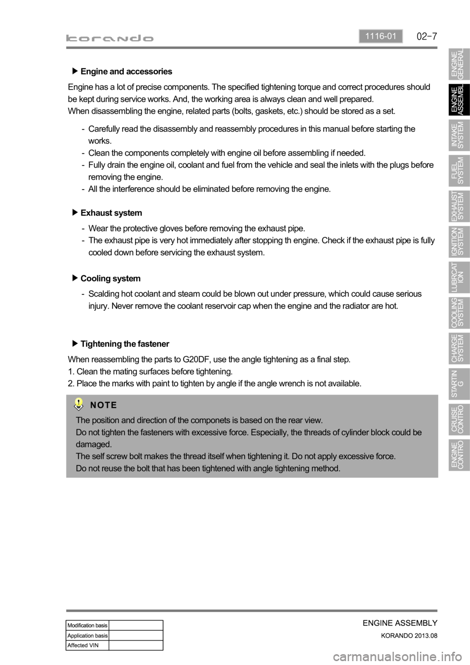
Engine and accessories
Engine has a lot of precise components. The specified tightening torque and correct procedures should
be kept during service works. And, the working area is always clean and well prepared.
When disassembling the engine, related parts (bolts, gaskets, etc.) should be stored as a set.
Carefully read the disassembly and reassembly procedures in this manual before starting the
works.
Clean the components completely with engine oil before assembling if needed.
Fully drain the engine oil, coolant and fuel from the vehicle and seal the inlets with the plugs before
removing the engine.
All the interference should be eliminated before removing the engine. -
-
-
-
Tightening the fastener
When reassembling the parts to G20DF, use the angle tightening as a final step.
1. Clean the mating surfaces before tightening.
2. Place the marks with paint to tighten by angle if the angle wrench is not available. Exhaust system
Wear the protective gloves before removing the exhaust pipe.
The exhaust pipe is very hot immediately after stopping th engine. Check if the exhaust pipe is fully
cooled down before servicing the exhaust system. -
-
Cooling system
Scalding hot coolant and steam could be blown out under pressure, which could cause serious
injury. Never remove the coolant reservoir cap when the engine and the radiator are hot. -
The position and direction of the componets is based on the rear view.
Do not tighten the fasteners with excessive force. Especially, the threads of cylinder block could be
damaged.
The self screw bolt makes the thread itself when tightening it. Do not apply excessive force.
Do not reuse the bolt that has been tightened with angle tightening method.
Page 453 of 1336
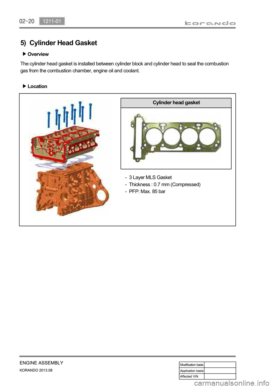
5) Cylinder Head Gasket
The cylinder head gasket is installed between cylinder block and cylinder head to seal the combustion
gas from the combustion chamber, engine oil and coolant.Overview
Location
Cylinder head gasket
3 Layer MLS Gasket
Thickness : 0.7 mm (Compressed)
PFP: Max. 85 bar -
-
-
Page 470 of 1336
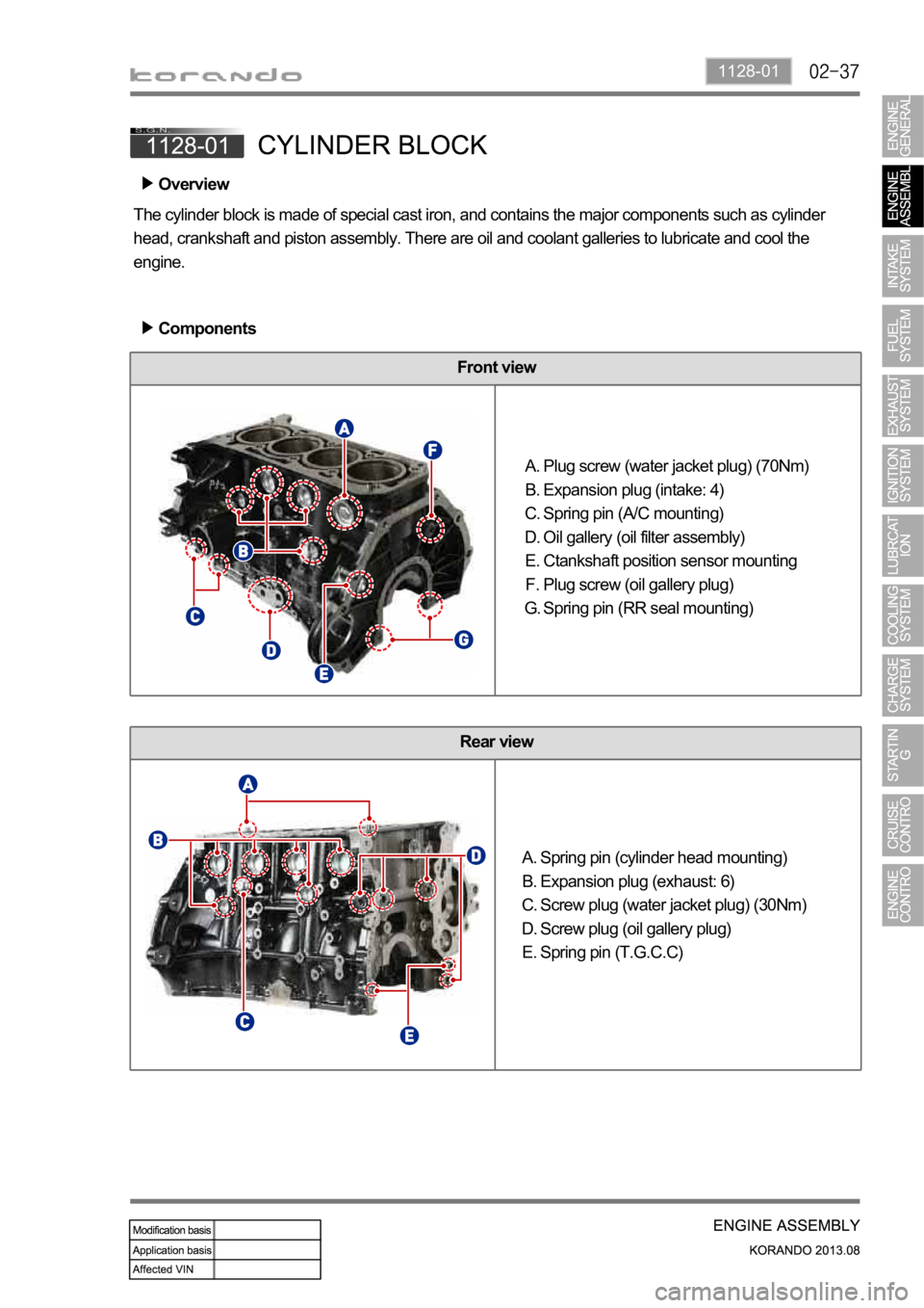
1128-01
Front view
Rear view
Spring pin (cylinder head mounting)
Expansion plug (exhaust: 6)
Screw plug (water jacket plug) (30Nm)
Screw plug (oil gallery plug)
Spring pin (T.G.C.C) A.
B.
C.
D.
E.
Overview
The cylinder block is made of special cast iron, and contains the major components such as cylinder
head, crankshaft and piston assembly. There are oil and coolant galleries to lubricate and cool the
engine.
Components
Plug screw (water jacket plug) (70Nm)
Expansion plug (intake: 4)
Spring pin (A/C mounting)
Oil gallery (oil filter assembly)
Ctankshaft position sensor mounting
Plug screw (oil gallery plug)
Spring pin (RR seal mounting) A.
B.
C.
D.
E.
F.
G.
Page 471 of 1336
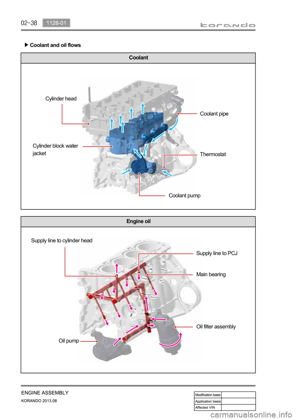
Engine oil
Coolant
Coolant and oil flows
Cylinder head
Cylinder block water
jacket
Coolant pumpCoolant pipe
Thermostat
Supply line to cylinder head
Oil pumpSupply line to PCJ
Main bearing
Oil filter assembly
Page 500 of 1336
1443-01
1. OVERVIEW
The ignition system is to supply high voltage generated from the ignition coil to the spark plug. The
G20DF engine is equipped with the independent type direct ignition system that the ignition coil is
installed in each cylinder.
The basic ignition timing in each cylinder is determined by the signals from camshaft position sensor and
crankshaft position sensor.
This ignition system controls the electronic ignition timing received from the engine ECU. To control the
ignition timing precisely, the ECU use the information below:
Engine load
Coolant temperature
Intake air temperature
Engine rpm
Camshaft position sensor (CPS)
Crankshaft position sensor (CKS) -
-
-
-
-
-
If the signal from the camshaft position sensor is not delivered to the engine ECU, the ignition coil and
fuel system cannot be operated.
Page 502 of 1336

1443-01
Electric throttle valveT-MAP sensorAccelerator pedal position
sensor
Coolant temperature
sensor
Engine ECU
Crankshaft position
sensor
Page 513 of 1336
2112-01
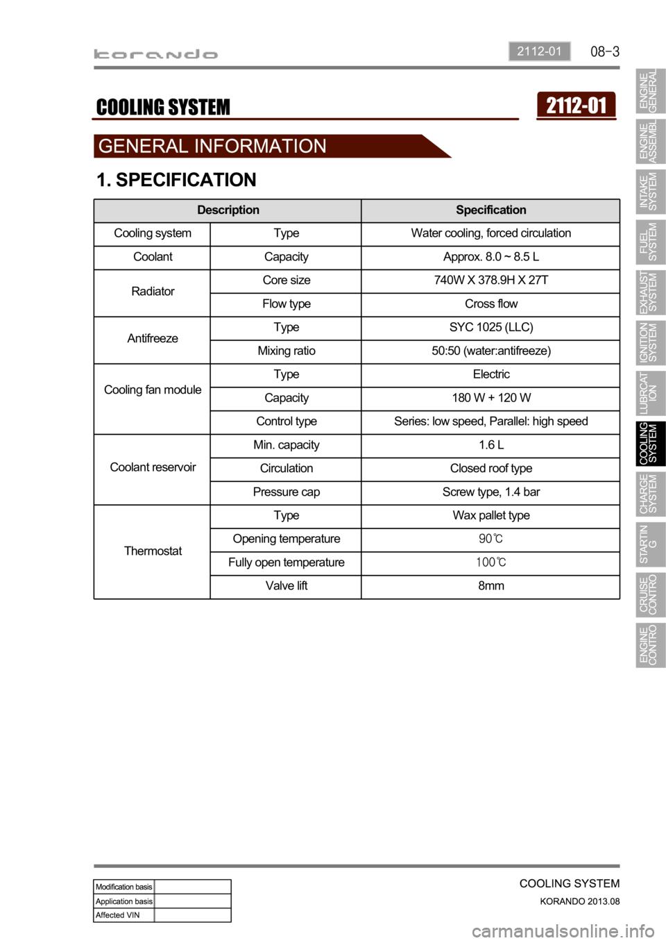
1. SPECIFICATION
Description Specification
Cooling system Type Water cooling, forced circulation
Coolant Capacity Approx. 8.0 ~ 8.5 L
RadiatorCore size 740W X 378.9H X 27T
Flow type Cross flow
AntifreezeType SYC 1025 (LLC)
Mixing ratio 50:50 (water:antifreeze)
Cooling fan moduleType Electric
Capacity 180 W + 120 W
Control type Series: low speed, Parallel: high speed
Coolant reservoirMin. capacity 1.6 L
Circulation Closed roof type
Pressure cap Screw type, 1.4 bar
ThermostatType Wax pallet type
Opening temperature
Fully open temperature
Valve lift 8mm
Page 514 of 1336
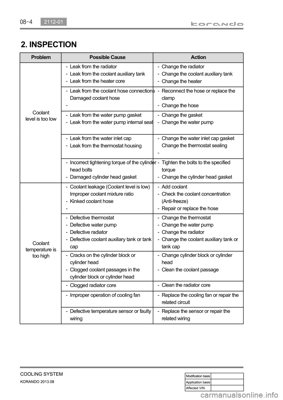
Problem Possible Cause Action
Coolant
level is too low
Coolant
temperature is
too high
2. INSPECTION
Leak from the radiator
Leak from the coolant auxiliary tank
Leak from the heater core -
-
-
Leak from the water inlet cap
Leak from the thermostat housing -
-Reconnect the hose or replace the
clamp
Change the hose -
- Leak from the coolant hose connections
Damaged coolant hose -
-
Change the gasket
Change the water pump -
- Leak from the water pump gasket
Leak from the water pump internal seal -
-
Tighten the bolts to the specified
torque
Change the cylinder head gasket -
- Incorrect tightening torque of the cylinder
head bolts
Damaged cylinder head gasket -
-Change the water inlet cap gasket
Change the thermostat sealing -
-
Coolant leakage (Coolant level is low)
Improper coolant mixture ratio
Kinked coolant hose -
-
-Add coolant
Check the coolant concentration
(Anti-freeze)
Repair or replace the hose -
-
-
Defective thermostat
Defective water pump
Defective radiator
Defective coolant auxiliary tank or tank
cap -
-
-
-Change the thermostat
Change the water pump
Change the radiator
Change the coolant auxiliary tank or
tank cap -
-
-
-Change the radiator
Change the coolant auxiliary tank
Change the heater -
-
-
Cracks on the cylinder block or
cylinder head
Clogged coolant passages in the
cylinder block or cylinder head -
-Change cylinder block or cylinder
head
Clean the coolant passage -
-
Clogged radiator core -
Replace the sensor or repair the
related wiring - Improper operation of cooling fan -Clean the radiator core -
Defective temperature sensor or faulty
wiring -Replace the cooling fan or repair the
related circuit -