coolant temperature SSANGYONG KORANDO 2013 Workshop Manual
[x] Cancel search | Manufacturer: SSANGYONG, Model Year: 2013, Model line: KORANDO, Model: SSANGYONG KORANDO 2013Pages: 1336, PDF Size: 92.18 MB
Page 564 of 1336
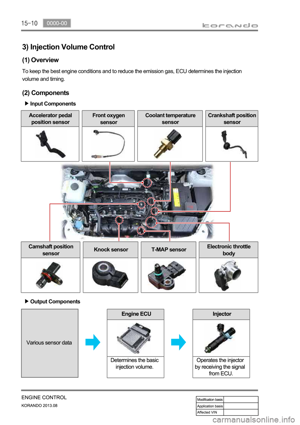
3) Injection Volume Control
(1) Overview
To keep the best engine conditions and to reduce the emission gas, ECU determines the injection
volume and timing.
(2) Components
Input Components
Accelerator pedal
position sensorFront oxygen
sensorCoolant temperature
sensorCrankshaft position
sensor
Camshaft position
sensorKnock sensorT-MAP sensorElectronic throttle
body
Output Components
Page 567 of 1336
0000-00
Coolant temperature
sensor
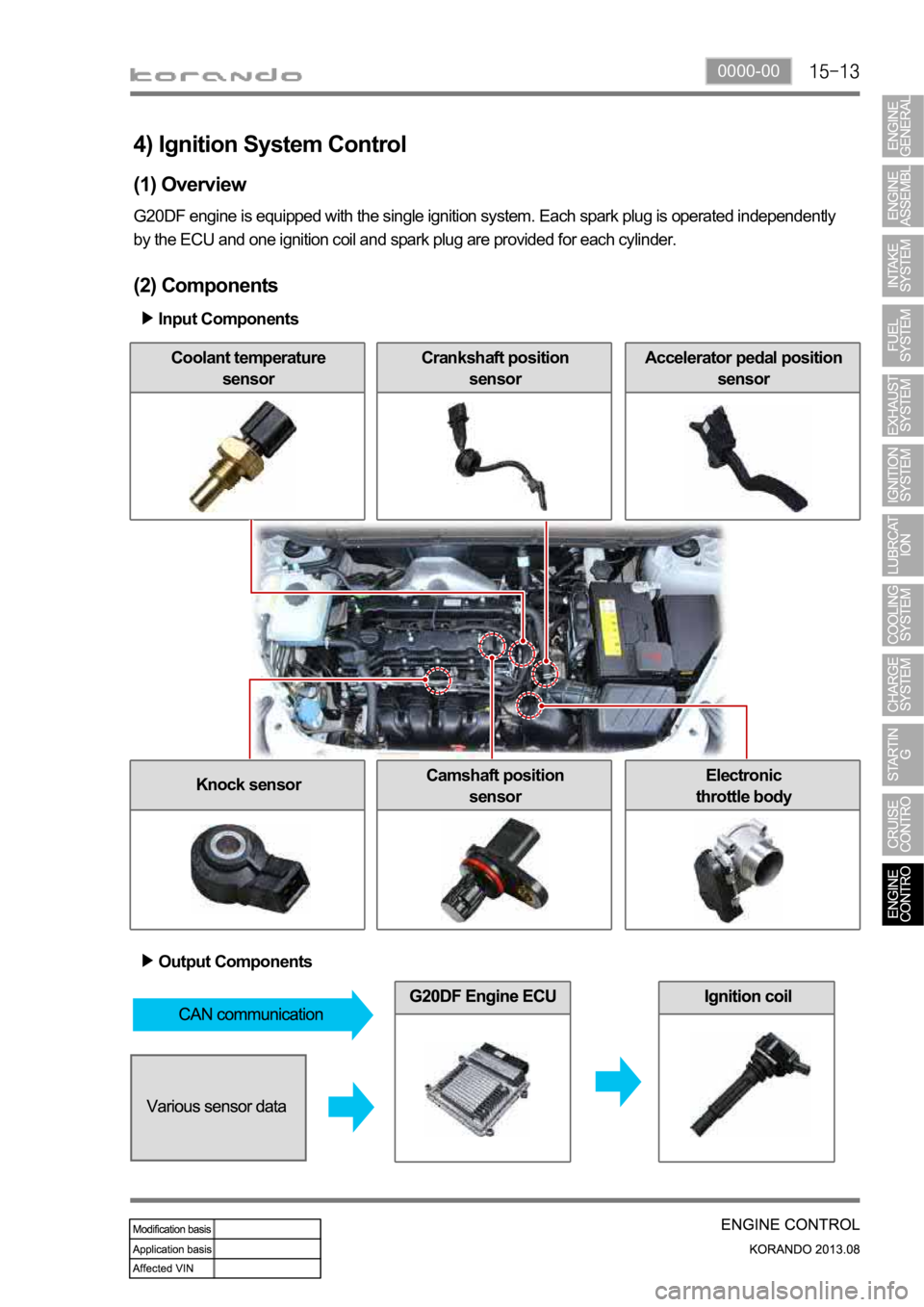
4) Ignition System Control
(1) Overview
G20DF engine is equipped with the single ignition system. Each spark plug is operated independently
by the ECU and one ignition coil and spark plug are provided for each cylinder.
(2) Components
Input Components
Crankshaft position
sensorAccelerator pedal position
sensor
Knock sensorCamshaft position
sensorElectronic
throttle body
Output Components
Page 569 of 1336
0000-00
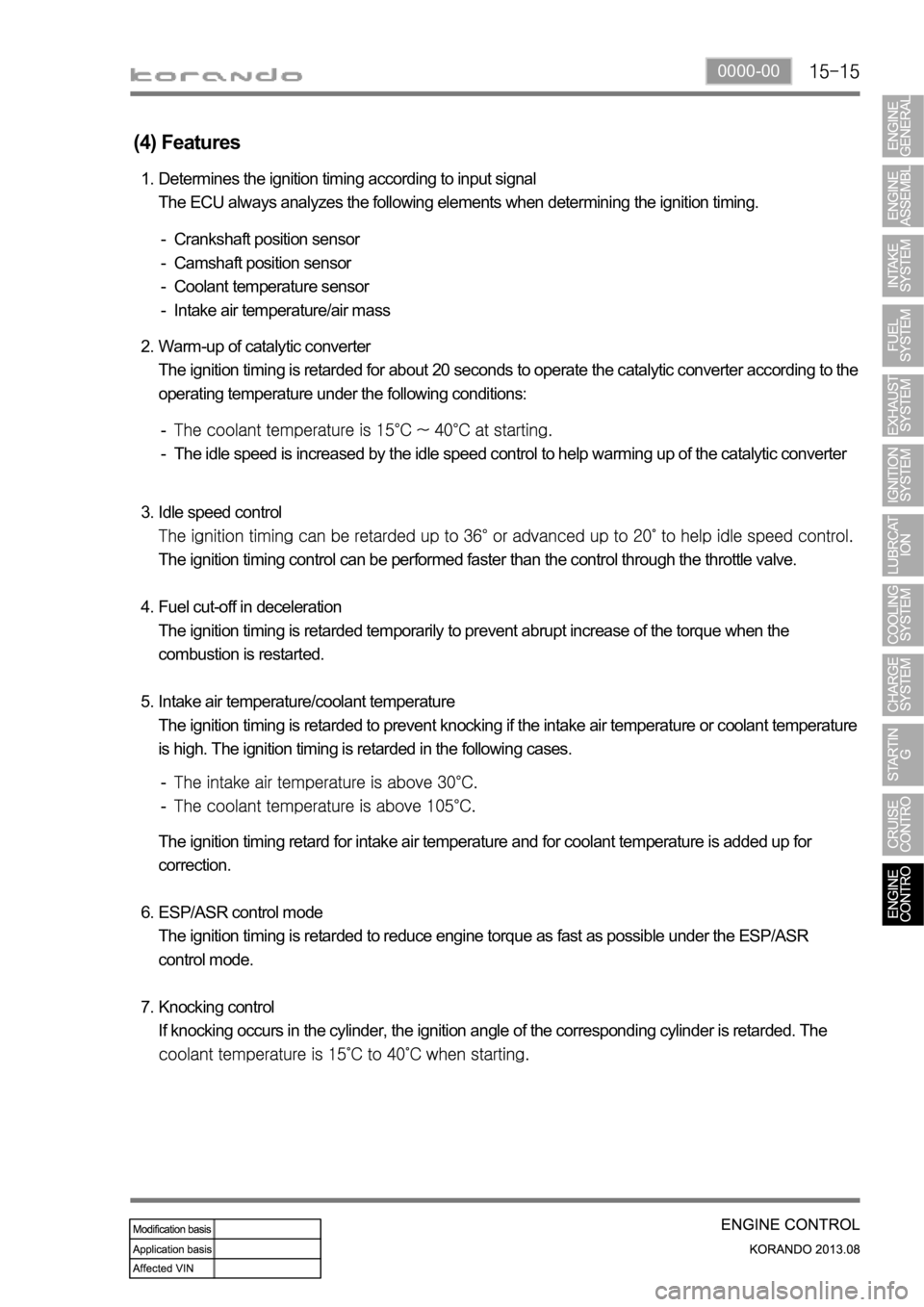
(4) Features
Determines the ignition timing according to input signal
The ECU always analyzes the following elements when determining the ignition timing. 1.
Crankshaft position sensor
Camshaft position sensor
Coolant temperature sensor
Intake air temperature/air mass -
-
-
-
Warm-up of catalytic converter
The ignition timing is retarded for about 20 seconds to operate the catalytic converter according to the
operating temperature under the following conditions: 2.
The idle speed is increased by the idle speed control to help warming up of the catalytic converter -
-
Idle speed control
The ignition timing control can be performed faster than the control through the throttle valve.
Fuel cut-off in deceleration
The ignition timing is retarded temporarily to prevent abrupt increase of the torque when the
combustion is restarted.
Intake air temperature/coolant temperature
The ignition timing is retarded to prevent knocking if the intake air temperature or coolant temperature
is high. The ignition timing is retarded in the following cases. 3.
4.
5.
-
-
The ignition timing retard for intake air temperature and for coolant temperature is added up for
correction.
ESP/ASR control mode
The ignition timing is retarded to reduce engine torque as fast as possible under the ESP/ASR
control mode.
Knocking control
If knocking occurs in the cylinder, the ignition angle of the corresponding cylinder is retarded. The
6.
7.
Page 570 of 1336
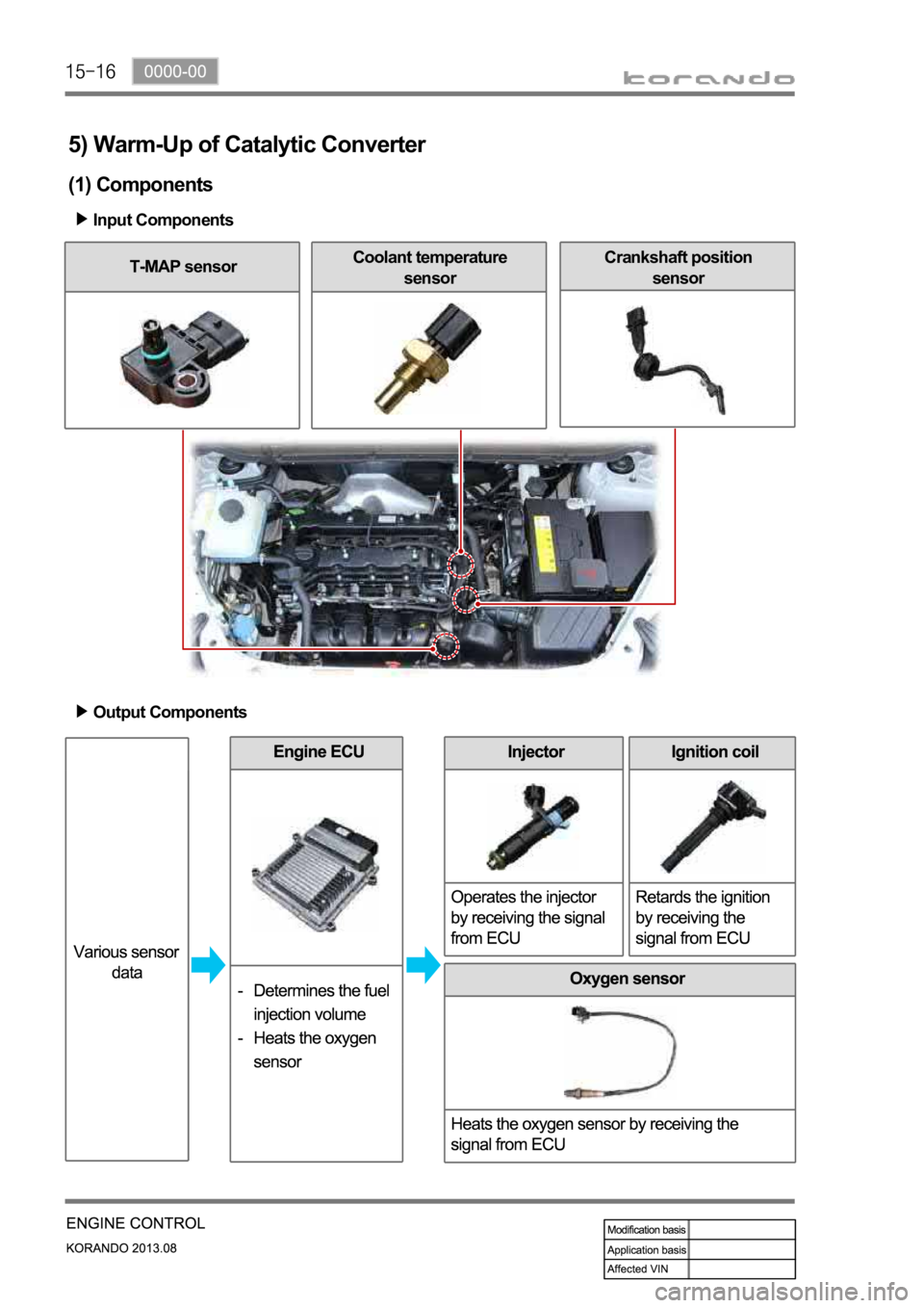
5) Warm-Up of Catalytic Converter
(1) Components
Input Components
T-MAP sensorCoolant temperature
sensorCrankshaft position
sensor
Output Components
Page 571 of 1336
0000-00
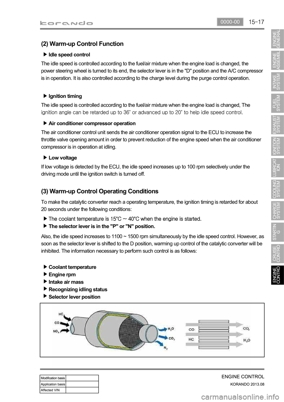
(2) Warm-up Control Function
Low voltage
If low voltage is detected by the ECU, the idle speed increases up to 100 rpm selectively under the
driving mode until the ignition switch is turned off. Idle speed control
The idle speed is controlled according to the fuel/air mixture when the engine load is changed, the
power steering wheel is turned to its end, the selector lever is in the "D" position and the A/C compresso
r
is in operation. It is also controlled according to the charge level during the purge control operation.
Ignition timing
The idle speed is controlled according to the fuel/air mixture when the engine load is changed, The
Air conditioner compressor operation
The air conditioner control unit sends the air conditioner operation signal to the ECU to increase the
throttle valve opening amount in order to prevent reduction of the engine speed when the air conditioner
compressor is in operation at idling.
(3) Warm-up Control Operating Conditions
To make the catalytic converter reach a operating temperature, the ignition timing is retarded for about
20 seconds under the following conditions:
The selector lever is in the "P" or "N" position.
Also, the idle speed increases to 1100 ~ 1500 rpm simultaneously by the idle speed control. However, as
soon as the selector lever is shifted to the D position, warming up control of the catalytic converter will be
inhibited. The information necessary to perform such control is as follows:
Coolant temperature
Engine rpm
Intake air mass
Recognizing idling status
Selector lever position
Page 572 of 1336
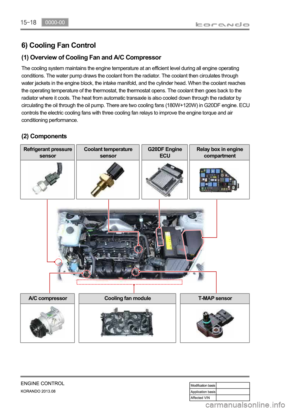
6) Cooling Fan Control
(1) Overview of Cooling Fan and A/C Compressor
The cooling system maintains the engine temperature at an efficient level during all engine operating
conditions. The water pump draws the coolant from the radiator. The coolant then circulates through
water jackets in the engine block, the intake manifold, and the cylinder head. When the coolant reaches
the operating temperature of the thermostat, the thermostat opens. The coolant then goes back to the
radiator where it cools. The heat from automatic transaxle is also cooled down through the radiator by
circulating the oil through the oil pump. There are two cooling fans (180W+120W) in G20DF engine. ECU
controls the electric cooling fans with three cooling fan relays to improve the engine torque and air
conditioning performance.
(2) Components
Refrigerant pressure
sensorCoolant temperature
sensorG20DF Engine
ECURelay box in engine
compartment
A/C compressorCooling fan moduleT-MAP sensor
Page 574 of 1336
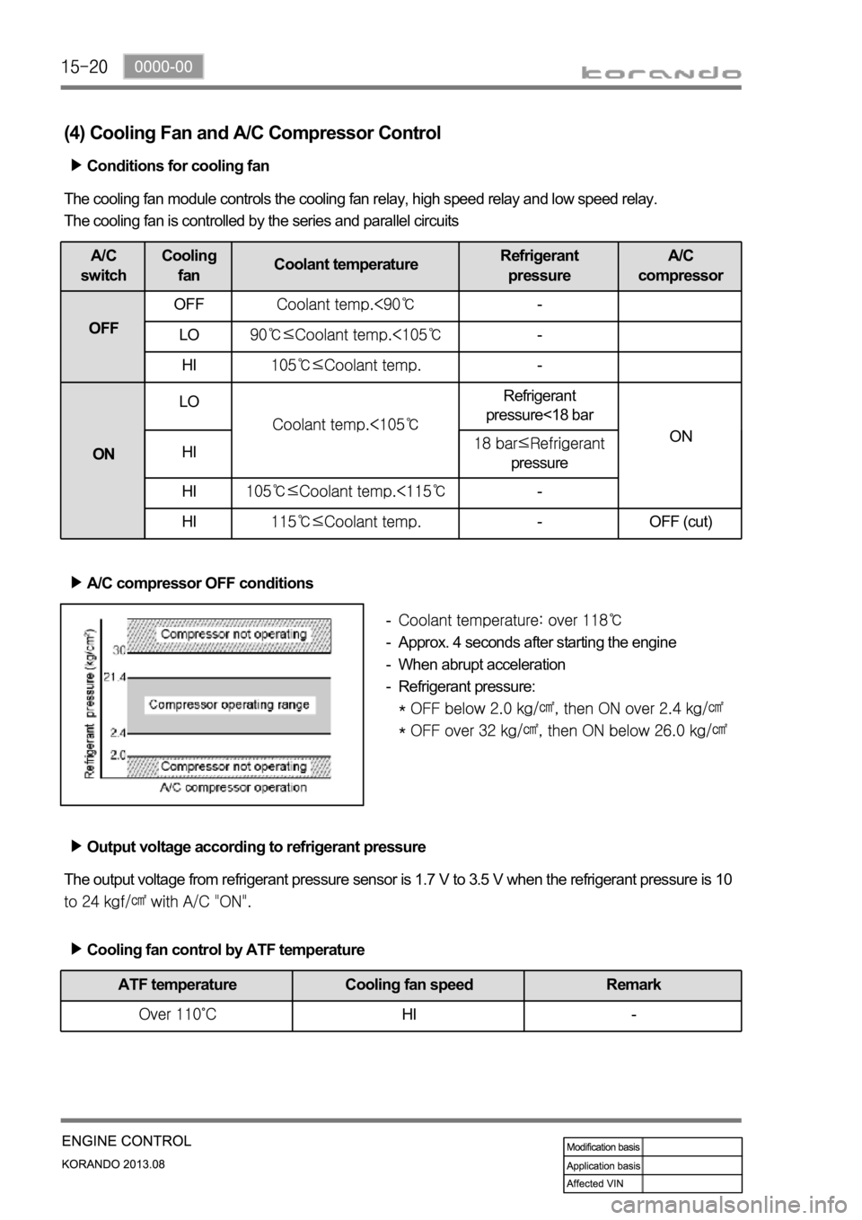
(4) Cooling Fan and A/C Compressor Control
Conditions for cooling fan
The cooling fan module controls the cooling fan relay, high speed relay and low speed relay.
The cooling fan is controlled by the series and parallel circuits
A/C
switchCooling
fanCoolant temperatureRefrigerant
pressureA/C
compressor
OFFOFF
-
LO
-
HI
-
ONLO
Refrigerant
pressure<18 bar
ON
HI
pressure
HI
-
HI
- OFF (cut)
A/C compressor OFF conditions
Approx. 4 seconds after starting the engine
When abrupt acceleration
Refrigerant pressure:
-
-
-
-
Output voltage according to refrigerant pressure
The output voltage from refrigerant pressure sensor is 1.7 V to 3.5 V when the refrigerant pressure is 10
Cooling fan control by ATF temperature
ATF temperature Cooling fan speed Remark
HI -
Page 774 of 1336
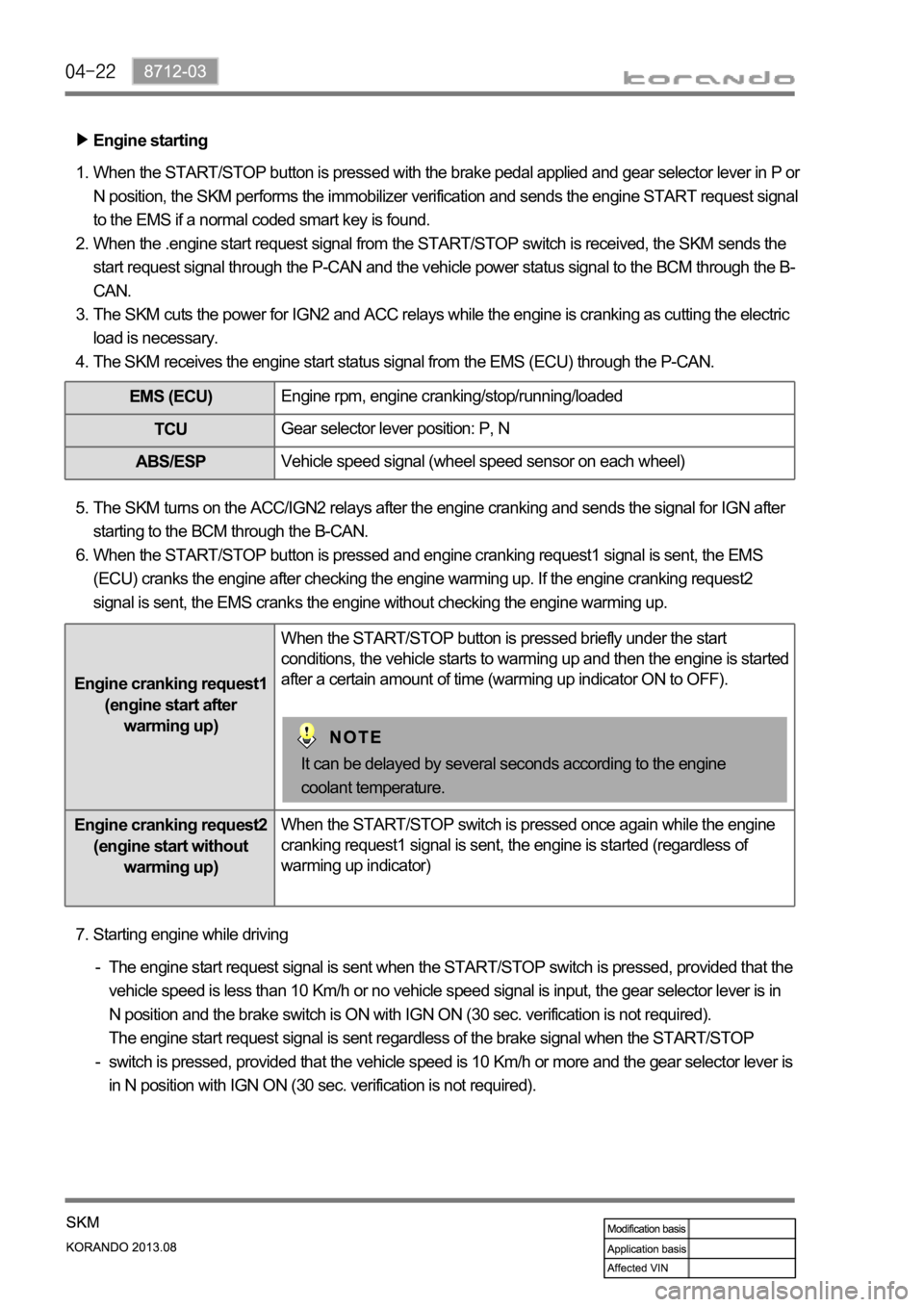
Engine starting
When the START/STOP button is pressed with the brake pedal applied and gear selector lever in P or
N position, the SKM performs the immobilizer verification and sends the engine START request signal
to the EMS if a normal coded smart key is found.
When the .engine start request signal from the START/STOP switch is received, the SKM sends the
start request signal through the P-CAN and the vehicle power status signal to the BCM through the B-
CAN.
The SKM cuts the power for IGN2 and ACC relays while the engine is cranking as cutting the electric
load is necessary.
The SKM receives the engine start status signal from the EMS (ECU) through the P-CAN. 1.
2.
3.
4.
EMS (ECU)Engine rpm, engine cranking/stop/running/loaded
TCUGear selector lever position: P, N
ABS/ESPVehicle speed signal (wheel speed sensor on each wheel)
The SKM turns on the ACC/IGN2 relays after the engine cranking and sends the signal for IGN after
starting to the BCM through the B-CAN.
When the START/STOP button is pressed and engine cranking request1 signal is sent, the EMS
(ECU) cranks the engine after checking the engine warming up. If the engine cranking request2
signal is sent, the EMS cranks the engine without checking the engine warming up. 5.
6.
Engine cranking request1
(engine start after
warming up)When the START/STOP button is pressed briefly under the start
conditions, the vehicle starts to warming up and then the engine is started
after a certain amount of time (warming up indicator ON to OFF).
Engine cranking request2
(engine start without
warming up)When the START/STOP switch is pressed once again while the engine
cranking request1 signal is sent, the engine is started (regardless of
warming up indicator)
It can be delayed by several seconds according to the engine
coolant temperature.
Starting engine while driving 7.
The engine start request signal is sent when the START/STOP switch is pressed, provided that the
vehicle speed is less than 10 Km/h or no vehicle speed signal is input, the gear selector lever is in
N position and the brake switch is ON with IGN ON (30 sec. verification is not required).
The engine start request signal is sent regardless of the brake signal when the START/STOP
switch is pressed, provided that the vehicle speed is 10 Km/h or more and the gear selector lever is
in N position with IGN ON (30 sec. verification is not required). -
-
Page 854 of 1336
8510-00
Heater and A/C control switch
Automatic Manual
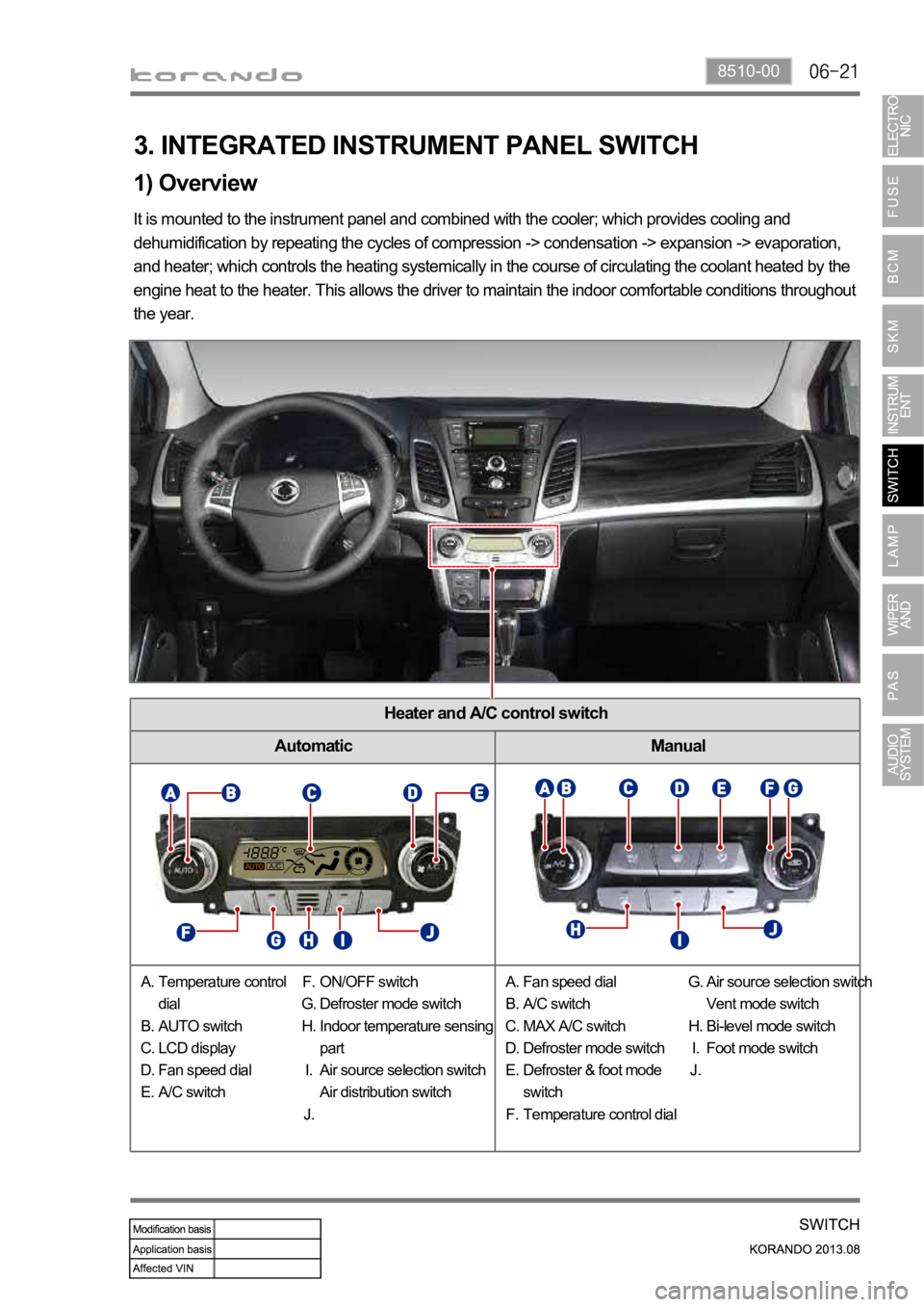
1) Overview
3. INTEGRATED INSTRUMENT PANEL SWITCH
It is mounted to the instrument panel and combined with the cooler; which provides cooling and
dehumidification by repeating the cycles of compression -> condensation -> expansion -> evaporation,
and heater; which controls the heating systemically in the course of circulating the coolant heated by the
engine heat to the heater. This allows the driver to maintain the indoor comfortable conditions throughout
the year.
Temperature control
dial
AUTO switch
LCD display
Fan speed dial
A/C switch A.
B.
C.
D.
E.ON/OFF switch
Defroster mode switch
Indoor temperature sensing
part
Air source selection switch
Air distribution switch F.
G.
H.
I.
J.Fan speed dial
A/C switch
MAX A/C switch
Defroster mode switch
Defroster & foot mode
switch
Temperature control dial A.
B.
C.
D.
E.
F.Air source selection switch
Vent mode switch
Bi-level mode switch
Foot mode switch G.
H.
I.
J.
Page 1014 of 1336
5. TRANSAXLE ELECTRONIC CONTROL SYSTEM
1) General Information
The transmission control unit (TCU) and its input/output network control the following transmission
operations:
Shift timing
Line pressure
Clutch pressure (shift feel)
Torque converter clutch -
-
-
-
also uses these signals when determining transaxle operating strategy. Using all of these input signals,
the TCU can determine when the time and conditions are right for a shift, or when to apply or release the
torque converter clutch. It will also determine the pressure needed to optimise shift feel. To accomplish
this, the TCU operates six variable bleed control solenoids and four on/off solenoids to control transaxle
operation.
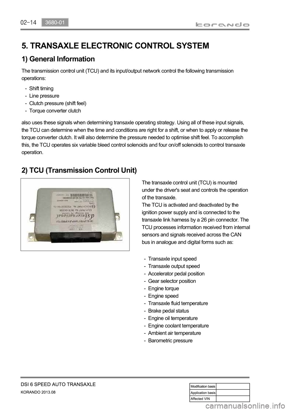
2) TCU (Transmission Control Unit)
The transaxle control unit (TCU) is mounted
under the driver's seat and controls the operation
of the transaxle.
The TCU is activated and deactivated by the
ignition power supply and is connected to the
transaxle link harness by a 26 pin connector. The
TCU processes information received from internal
sensors and signals received across the CAN
bus in analogue and digital forms such as:
Transaxle input speed
Transaxle output speed
Accelerator pedal position
Gear selector position
Engine torque
Engine speed
Transaxle fluid temperature
Brake pedal status
Engine oil temperature
Engine coolant temperature
Ambient air temperature
Barometric pressure -
-
-
-
-
-
-
-
-
-
-
-