SSANGYONG KORANDO 2013 Service Manual
KORANDO 2013
SSANGYONG
SSANGYONG
https://www.carmanualsonline.info/img/67/57503/w960_57503-0.png
SSANGYONG KORANDO 2013 Service Manual
Page 185 of 1336
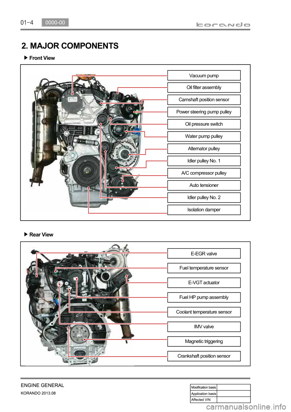
2. MAJOR COMPONENTS
Front View
Rear View
E-EGR valve
Fuel temperature sensor
Fuel HP pump assemblyE-VGT actuator
Coolant temperature sensor
IMV valve
Magnetic triggering
Crankshaft position sensor
Vacuum pump
Oil filter assembly
Camshaft position sensor
Power steering pump pulley
Water pump pulley
Alternator pulley
Idler pulley No. 1
A/C compressor pulley
Auto tensioner
Idler pulley No. 2
Isolation damper
Oil pressure switch
Page 186 of 1336
0000-00
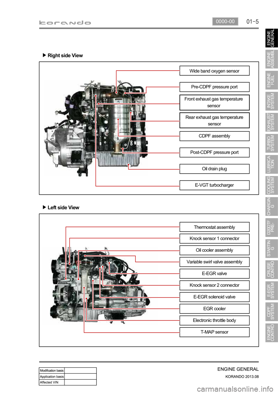
Right side View
Wide band oxygen sensor
Pre-CDPF pressure port
Rear exhaust gas temperature
sensor
CDPF assembly
E-VGT turbocharger Post-CDPF pressure port
Oil drain plug
Left side View
Thermostat assembly
Knock sensor 1 connector
Variable swirl valve assemblyOil cooler assembly
E-EGR valve
Knock sensor 2 connector
E-EGR solenoid valve
EGR cooler
Electronic throttle body
T-MAP sensor
Front exhaust gas temperature
sensor
Page 194 of 1336
0000-00
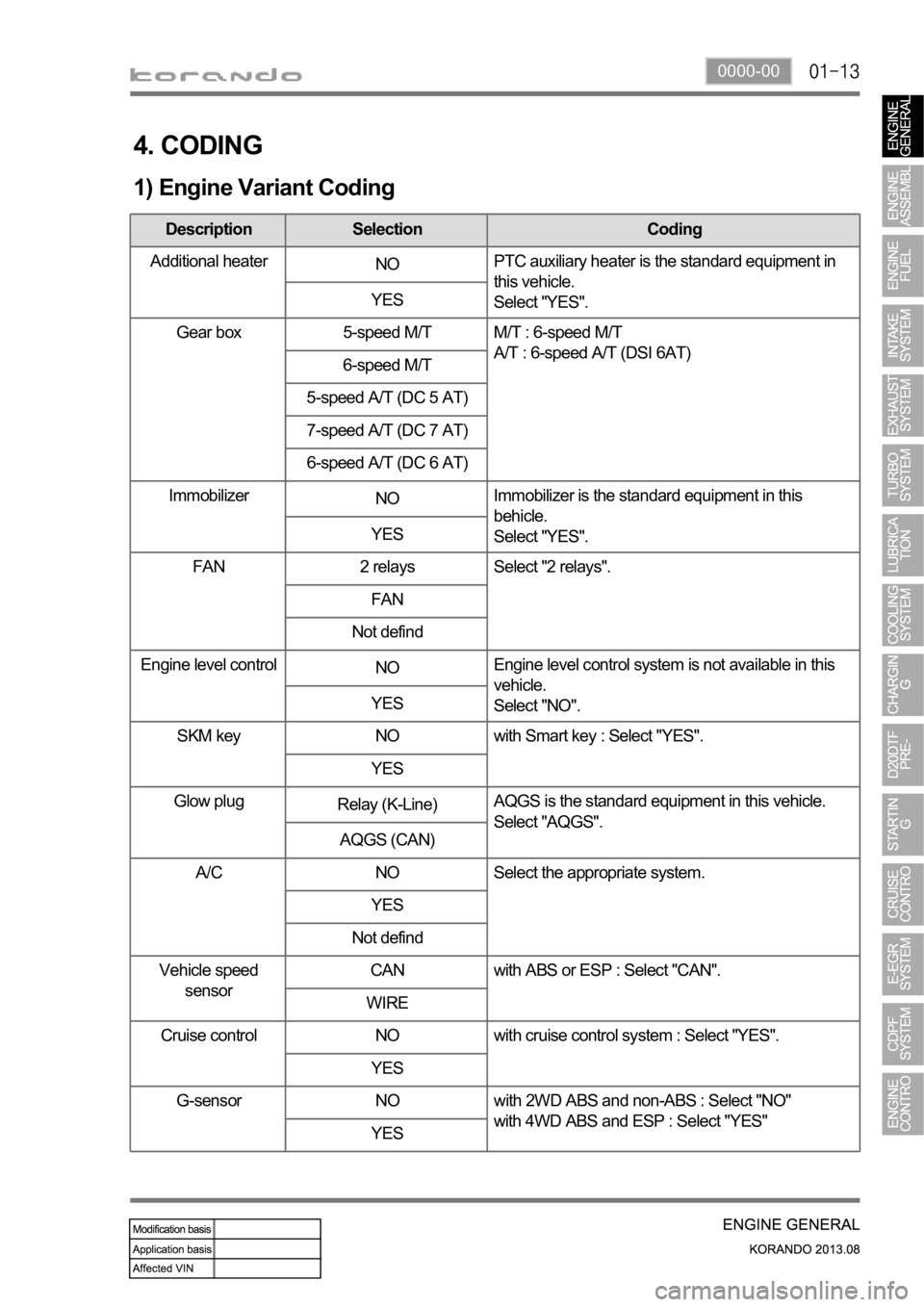
4. CODING
1) Engine Variant Coding
Description Selection Coding
Additional heater
NOPTC auxiliary heater is the standard equipment in
this vehicle.
Select "YES". YES
Gear box 5-speed M/T M/T : 6-speed M/T
A/T : 6-speed A/T (DSI 6AT)
6-speed M/T
5-speed A/T (DC 5 AT)
7-speed A/T (DC 7 AT)
6-speed A/T (DC 6 AT)
Immobilizer
NOImmobilizer is the standard equipment in this
behicle.
Select "YES". YES
FAN 2 relays Select "2 relays".
FAN
Not defind
Engine level control
NOEngine level control system is not available in this
vehicle.
Select "NO". YES
SKM key NO with Smart key : Select "YES".
YES
Glow plug
Relay (K-Line)AQGS is the standard equipment in this vehicle.
Select "AQGS".
AQGS (CAN)
A/C NO Select the appropriate system.
YES
Not defind
Vehicle speed
sensorCAN with ABS or ESP : Select "CAN".
WIRE
Cruise control NO with cruise control system : Select "YES".
YES
G-sensor NO with 2WD ABS and non-ABS : Select "NO"
with 4WD ABS and ESP : Select "YES"
YES
Page 197 of 1336
0000-00
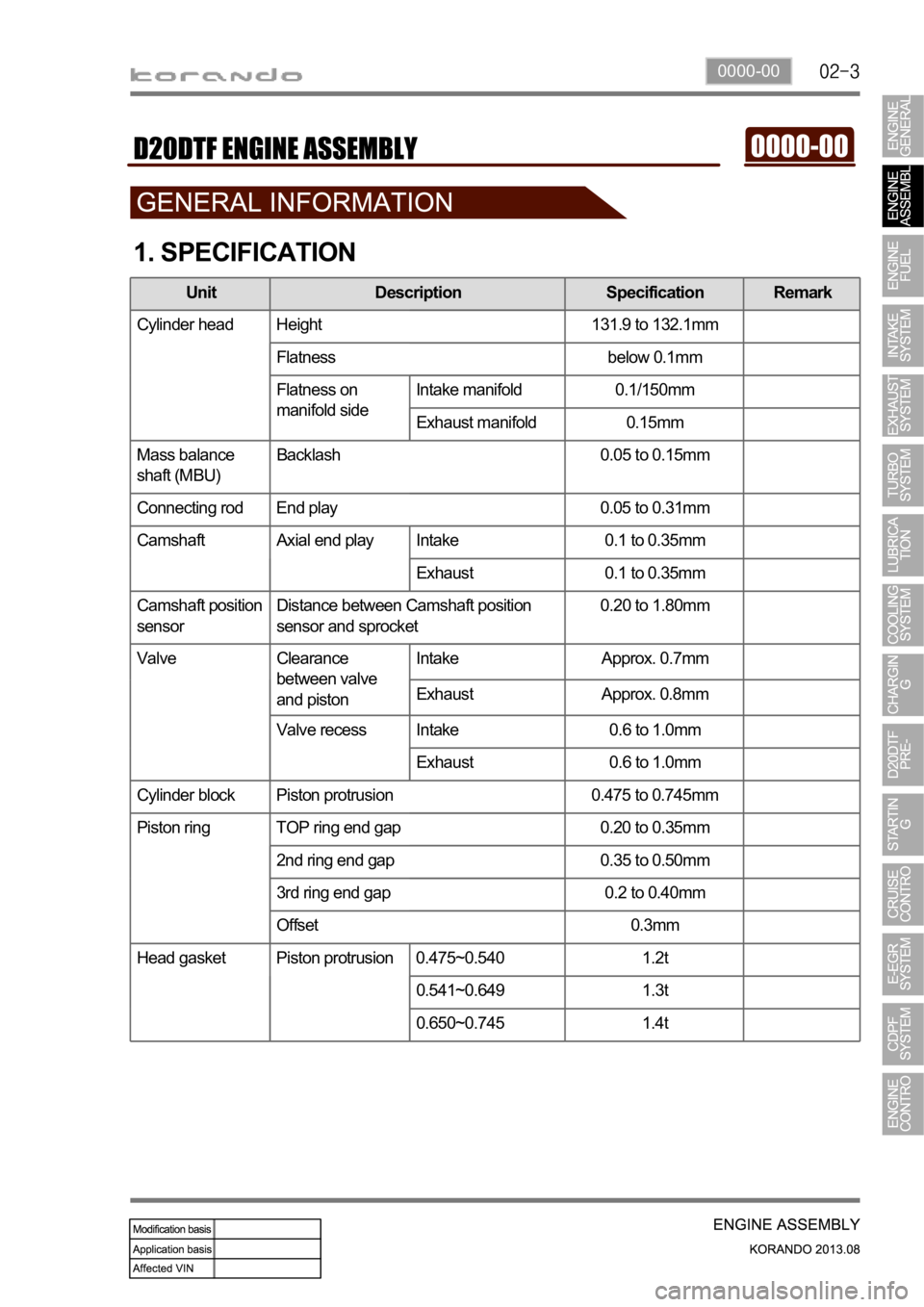
1. SPECIFICATION
Unit Description Specification Remark
Cylinder head Height 131.9 to 132.1mm
Flatness below 0.1mm
Flatness on
manifold sideIntake manifold 0.1/150mm
Exhaust manifold 0.15mm
Mass balance
shaft (MBU)Backlash 0.05 to 0.15mm
Connecting rod End play 0.05 to 0.31mm
Camshaft Axial end play Intake 0.1 to 0.35mm
Exhaust 0.1 to 0.35mm
Camshaft position
sensorDistance between Camshaft position
sensor and sprocket0.20 to 1.80mm
Valve Clearance
between valve
and pistonIntake Approx. 0.7mm
Exhaust Approx. 0.8mm
Valve recess Intake 0.6 to 1.0mm
Exhaust 0.6 to 1.0mm
Cylinder block Piston protrusion 0.475 to 0.745mm
Piston ring TOP ring end gap 0.20 to 0.35mm
2nd ring end gap 0.35 to 0.50mm
3rd ring end gap 0.2 to 0.40mm
Offset 0.3mm
Head gasket Piston protrusion 0.475~0.540 1.2t
0.541~0.649 1.3t
0.650~0.745 1.4t
Page 200 of 1336
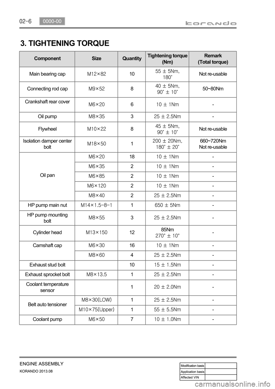
3. TIGHTENING TORQUE
Component Size QuantityTightening torque
(Nm)Remark
(Total torque)
Main bearing cap
10Not re-usable
Connecting rod cap
850~80Nm
Crankshaft rear cover
6-
Oil pump
3-
Flywheel
8Not re-usable
Isolation damper center
bolt
1660~720Nm
Not re-usable
Oil pan
18-
2-
2-
2-
2-
HP pump main nut
1-
HP pump mounting
bolt
3-
Cylinder head
1285Nm-
Camshaft cap
16-
4-
Exhaust stud bolt 10
-
Exhaust sprocket bolt
1-
Coolant temperature
sensor1-
Belt auto tensioner
1-
1-
Coolant pump
7-
Page 201 of 1336
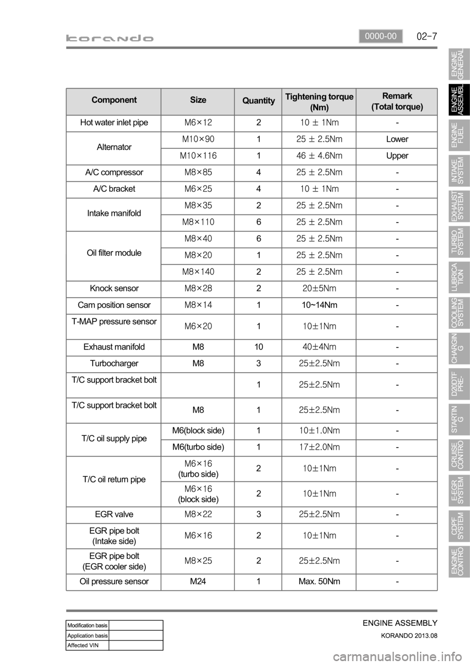
0000-00
Knock sensor2-
Cam position sensor
1 10~14Nm -
T-MAP pressure sensor
1-
Exhaust manifold M8 10
-
Turbocharger M8 3
-
T/C support bracket bolt
1
-
T/C support bracket bolt
M8 1
-
T/C oil supply pipeM6(block side) 1
-
M6(turbo side) 1
-
T/C oil return pipe
(turbo side)2-
(block side)2-
EGR valve
3-
EGR pipe bolt
(Intake side)
2-
EGR pipe bolt
(EGR cooler side)
2-
Oil pressure sensor M24 1 Max. 50Nm -
Component Size
QuantityTightening torque
(Nm)Remark
(Total torque)
Hot water inlet pipe
2-
Alternator
1Lower
1Upper
A/C compressor
4-
A/C bracket
4-
Intake manifold
2-
6-
Oil filter module
6-
1-
2-
Page 202 of 1336
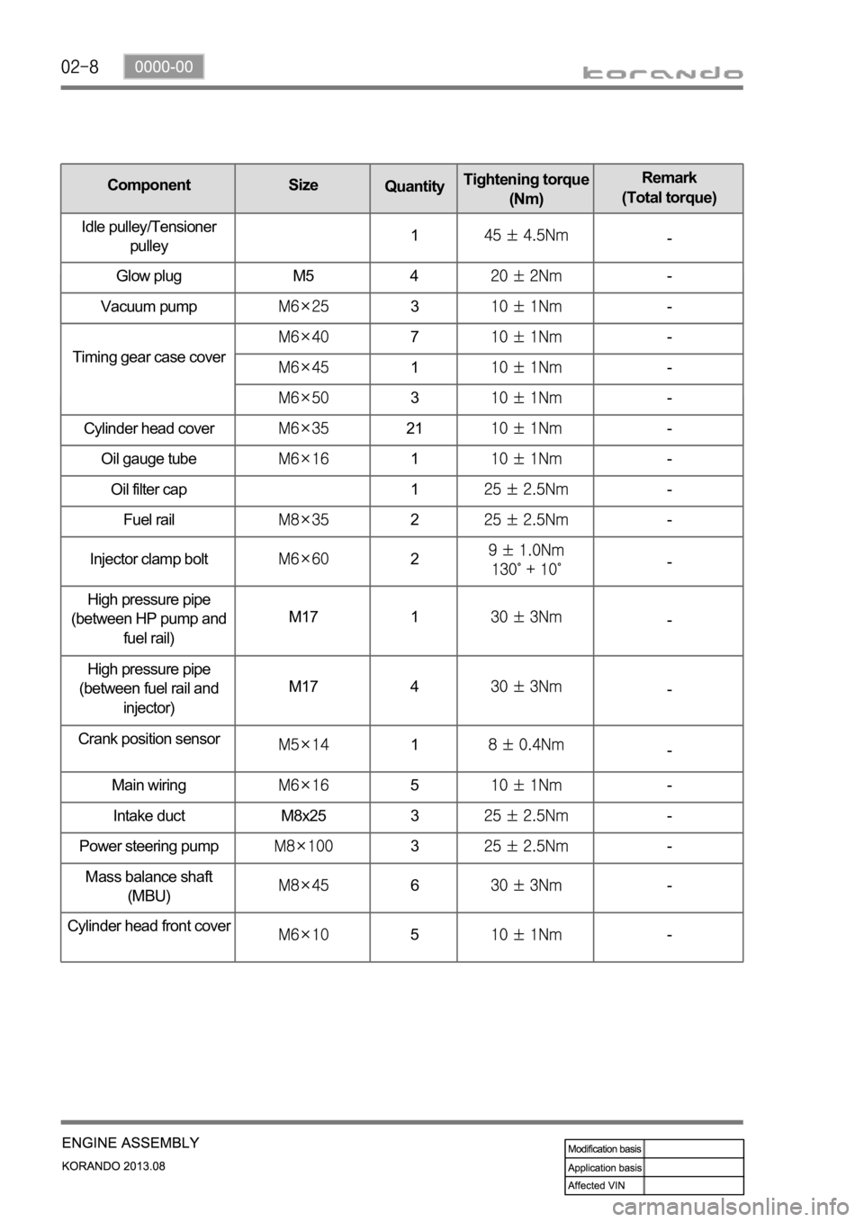
Oil gauge tube1-
Oil filter cap 1
-
Fuel rail
2-
Injector clamp bolt
2-
High pressure pipe
(between HP pump and
fuel rail)M17 1
-
High pressure pipe
(between fuel rail and
injector)M17 4
-
Crank position sensor
1-
Main wiring
5-
Intake duct M8x25 3
-
Power steering pump
3-
Mass balance shaft
(MBU)
6-
Cylinder head front cove
r5-
Timing gear case cover
7-
1-
3-
Cylinder head cover
21-
Component Size
QuantityTightening torque
(Nm)Remark
(Total torque)
Idle pulley/Tensioner
pulley1
-
Glow plug M5 4
-
Vacuum pump
3-
Page 217 of 1336
0000-00
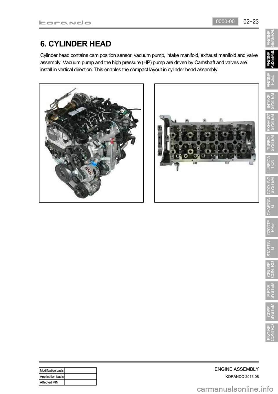
6. CYLINDER HEAD
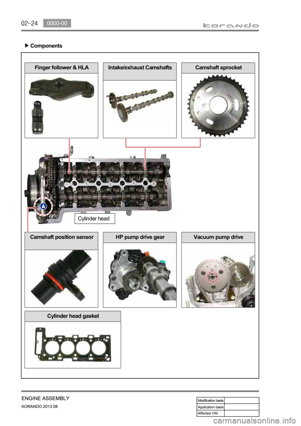
Cylinder head contains cam position sensor, vacuum pump, intake manifold, exhaust manifold and valve
assembly. Vacuum pump and the high pressure (HP) pump are driven by Camshaft and valves are
install in vertical direction. This enables the compact layout in cylinder head assembly.
Page 218 of 1336
Vacuum pump drive
Intake/exhaust CamshaftsCamshaft sprocketFinger follower & HLA
Components
Cylinder head
Camshaft position sensorHP pump drive gear
Cylinder head gasket
Page 238 of 1336
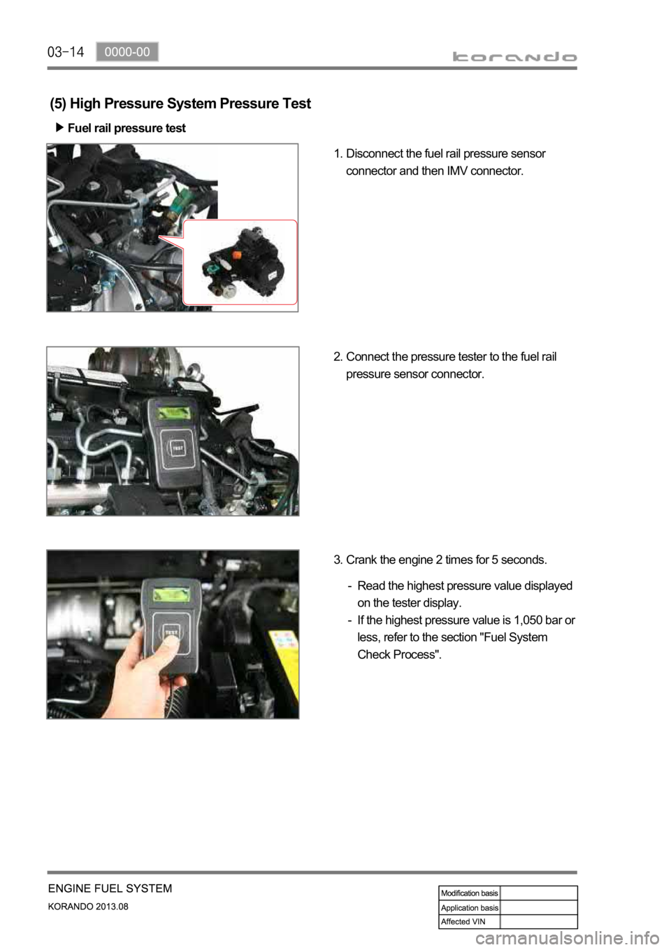
(5) High Pressure System Pressure Test
Fuel rail pressure test
Disconnect the fuel rail pressure sensor
connector and then IMV connector. 1.
Connect the pressure tester to the fuel rail
pressure sensor connector. 2.
Crank the engine 2 times for 5 seconds. 3.
Read the highest pressure value displayed
on the tester display.
If the highest pressure value is 1,050 bar or
less, refer to the section "Fuel System
Check Process". -
-
