sensor SSANGYONG KORANDO 2013 Workshop Manual
[x] Cancel search | Manufacturer: SSANGYONG, Model Year: 2013, Model line: KORANDO, Model: SSANGYONG KORANDO 2013Pages: 1336, PDF Size: 92.18 MB
Page 387 of 1336
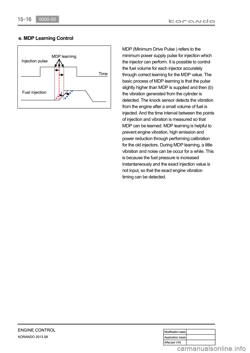
e. MDP Learning Control
MDP (Minimum Drive Pulse ) refers to the
minimum power supply pulse for injection which
the injector can perform. It is possible to control
the fuel volume for each injector accurately
through correct learning for the MDP value. The
basic process of MDP learning is that the pulse
slightly higher than MDP is supplied and then (b)
the vibration generated from the cylinder is
detected. The knock sensor detects the vibration
from the engine after a small volume of fuel is
injected. And the time interval between the points
of injection and vibration is measured so that
MDP can be learned. MDP learning is helpful to
prevent engine vibration, high emission and
power reduction through performing calibration
for the old injectors. During MDP learning, a little
vibration and noise can be occur for a while. This
is because the fuel pressure is increased
instantaneously and the exact injection value is
not input, so that the exact engine vibration
timing can be detected.
Page 388 of 1336
0000-00
(3) Accelerometer Control
a. Resetting the pilot injection
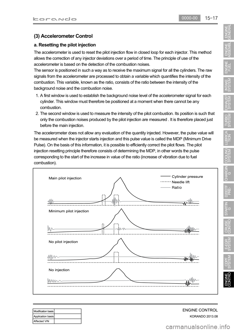
The accelerometer is used to reset the pilot injection flow in closed loop for each injector. This method
allows the correction of any injector deviations over a period of time. The principle of use of the
accelerometer is based on the detection of the combustion noises.
The sensor is positioned in such a way as to receive the maximum signal for all the cylinders. The raw
signals from the accelerometer are processed to obtain a variable which quantifies the intensity of the
combustion. This variable, known as the ratio, consists of the ratio between the intensity of the
background noise and the combustion noise.
A first window is used to establish the background noise level of the accelerometer signal for each
cylinder. This window must therefore be positioned at a moment when there cannot be any
combustion.
The second window is used to measure the intensity of the pilot combustion. Its position is such that
only the combustion noises produced by the pilot injection are measured . It is therefore placed just
before the main injection. 1.
2.
The accelerometer does not allow any evaluation of the quantity injected. However, the pulse value will
be measured when the injector starts injection and this pulse value is called the MDP (Minimum Drive
Pulse). On the basis of this information, it is possible to efficiently correct the pilot flows. The pilot
injection resetting principle therefore consists of determining the MDP, in other words the pulse
corresponding to the start of the increase in value of the ratio (increase of vibration due to fuel
combustion).
Page 389 of 1336
This is done periodically under certain operating conditions. When the resetting is finished, the new
minimum pulse value replaces the value obtained during the previous resetting. The first MDP value is
provided by the C3I. Each resetting then allows the closed loop of the MDP to be updated according to
the deviation of the injector.
b. Detection of leaks in the cylinders
The accelerometer is also used to detect any injector which may have stuck open. The detection
principle is based on monitoring the ratio. If there is a leak in the cylinder, the accumulated fuel self-
ignites as soon as the temperature and pressure conditions are favorable (high engine speed, high load
and small leak).
This combustion is set off at about 20 degrees before TDC and before main injection.
The ratio therefore increases considerably in the detection window. It is this increase which allows the
leaks to be detected. The threshold beyond which a fault is signaled is a percentage of the maximum
possible value of the ratio.
Because of the severity of the recovery process (engine shut-down), the etection must be extremely
robust.
An increase in the ratio can be the consequence of various causes:
Pilot injection too much
Main combustion offset
Fuel leak in the cylinder -
-
-
If the ratio becomes too high, the strategy initially restricts the pilot injection flow and retards the main
injection. If the ratio remains high despite these interventions, this shows that a real leak is present, a
fault is signaled and the engine is shut down.
c. Detection of an accelerometer fault
This strategy permits the detection of a fault in the sensor or in the wiring loom connecting the sensor to
the ECU.
It is based on detection of the combustion. When the engine is idling, the detection window is set too low
for the combustion caused by the main injection. If the ratio increases, this shows that the accelerometer
is working properly, but otherwise a fault is signaled to indicate a sensor failure. The recovery modes
associated with this fault consist of inhibition of the pilot injection and discharge through the injectors.
Page 390 of 1336
0000-00
HFM
Accelerator pedalCoolant
temperature
(4) Swirl control
a. Overview
Variable swirl valve -
The strong swirl caused by intake air is important element for anti-locking function in diesel engine. The
swirl control valve partially closes the intake port to generate the swirl according to the engine conditions.
When the engine load is in low or medium range, the swirl could not be generated because the air flow
is slow. To generate strong swirl, there are two passages in intake manifold, and one of them has the
valve to open and close the passage. When the valve closes the passage, the air flow through the
another passage will be faster, and the strong swirl will be generated by the internal structure of the
passage. This swirl makes the better mixture of air and fuel, eventually the combustion efficiency in
combustion chamber could be improved. This provides the enhanced fuel consumption, power and
EGR ratio.
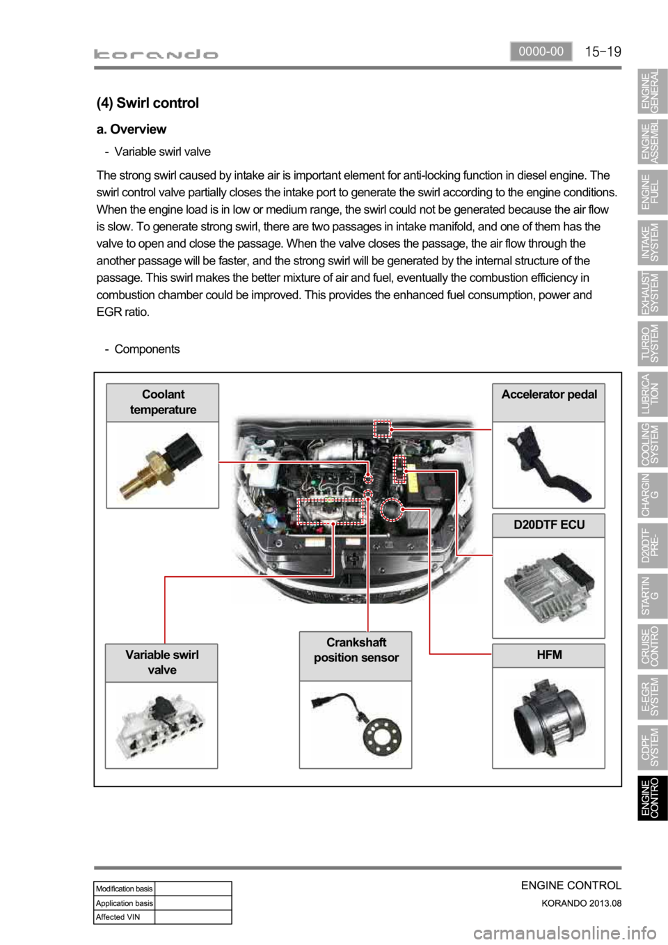
Components -
D20DTF ECU
Crankshaft
position sensor
Variable swirl
valve
Page 395 of 1336
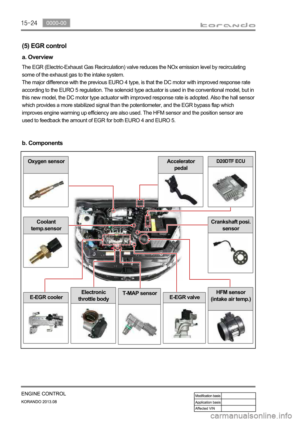
T-MAP sensor
D20DTF ECUOxygen sensor
Electronic
throttle bodyHFM sensor
(intake air temp.)
Coolant
temp.sensor
E-EGR valve
Crankshaft posi.
sensor
Accelerator
pedal
E-EGR cooler
(5) EGR control
a. Overview
The EGR (Electric-Exhaust Gas Recirculation) valve reduces the NOx emission level by recirculating
some of the exhaust gas to the intake system.
The major difference with the previous EURO 4 type, is that the DC motor with improved response rate
according to the EURO 5 regulation. The solenoid type actuator is used in the conventional model, but in
this new model, the DC motor type actuator with improved response rate is adopted. Also the hall senso
r
which provides a more stabilized signal than the potentiometer, and the EGR bypass flap which
improves engine warming up efficiency are also used. The HFM sensor and the position sensor are
used to feedback the amount of EGR for both EURO 4 and EURO 5.
b. Components
Page 397 of 1336
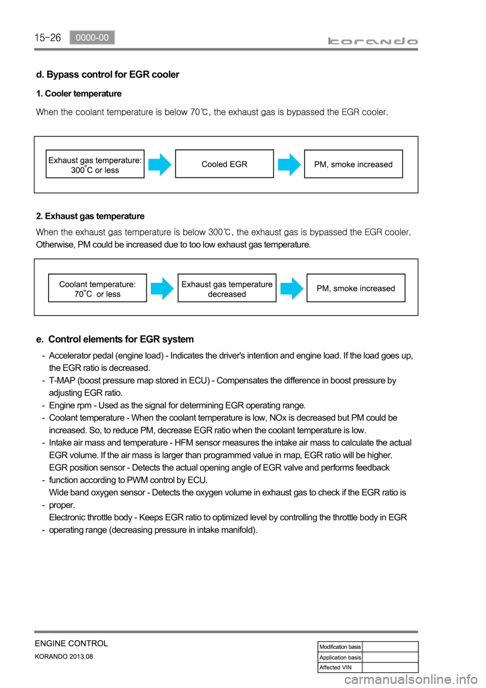
d. Bypass control for EGR cooler
1. Cooler temperature
2. Exhaust gas temperature
Otherwise, PM could be increased due to too low exhaust gas temperature.
e. Control elements for EGR system
Accelerator pedal (engine load) - Indicates the driver's intention and engine load. If the load goes up,
the EGR ratio is decreased.
T-MAP (boost pressure map stored in ECU) - Compensates the difference in boost pressure by
adjusting EGR ratio.
Engine rpm - Used as the signal for determining EGR operating range.
Coolant temperature - When the coolant temperature is low, NOx is decreased but PM could be
increased. So, to reduce PM, decrease EGR ratio when the coolant temperature is low.
Intake air mass and temperature - HFM sensor measures the intake air mass to calculate the actual
EGR volume. If the air mass is larger than programmed value in map, EGR ratio will be higher.
EGR position sensor - Detects the actual opening angle of EGR valve and performs feedback
function according to PWM control by ECU.
Wide band oxygen sensor - Detects the oxygen volume in exhaust gas to check if the EGR ratio is
proper.
Electronic throttle body - Keeps EGR ratio to optimized level by controlling the throttle body in EGR
operating range (decreasing pressure in intake manifold). -
-
-
-
-
-
-
-
Page 399 of 1336
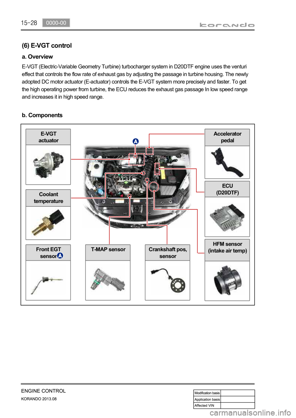
Accelerator
pedalE-VGT
actuator
Coolant
temperature
Front EGT
sensorT-MAP sensorCrankshaft pos,
sensor
HFM sensor
(intake air temp)
ECU
(D20DTF)
(6) E-VGT control
a. Overview
E-VGT (Electric-Variable Geometry Turbine) turbocharger system in D20DTF engine uses the venturi
effect that controls the flow rate of exhaust gas by adjusting the passage in turbine housing. The newly
adopted DC motor actuator (E-actuator) controls the E-VGT system more precisely and faster. To get
the high operating power from turbine, the ECU reduces the exhaust gas passage In low speed range
and increases it in high speed range.
b. Components
Page 402 of 1336

0000-00
HFM sensor
(air mass)
CDPF
(7) Wide band oxygen sensor
a. Overview
For diesel engine, combustion is not performed at the optimum (theoretically correct) air-fuel ratio and
the oxygen concentration is thin in most cases. So the wide-band oxygen sensor is used for this kind of
engine, and this sensor is a little different from the one that used for gasoline engine. The combustion in
diesel engine is controlled by fuel injection volume. Therefore, the wide band oxygen sensor should be
used in diesel engine. This sensor measures the air-fuel ratio in very wide range, and is also called full
range oxygen sensor.
The wide band oxygen sensor measures the oxygen density in exhaust gas and sends it to ECU to
control the EGR more precisely. -
b. Components
D20DTF
ECU
EGR valveElectronic
throttle bodyCoolant temp.
sensor
Oxygen
sensorInjector (C3I)
Page 403 of 1336

c. Input/Output for oxygen sensor
Page 404 of 1336

0000-00
d. Oxygen sensor control
The wide band oxygen sensor uses ZnO2. It produces the voltage by movement of oxygen ions when
there is oxygen concentration difference between exhaust gas and atmosphere.
If a certain voltage is applied to the sensor, the movement of oxygen ions occurs regardless of the
oxygen density. The current generated through this flow of ions, is called pumping current (IP), and the
oxygen sensor measures this value.