sensor SSANGYONG KORANDO 2013 User Guide
[x] Cancel search | Manufacturer: SSANGYONG, Model Year: 2013, Model line: KORANDO, Model: SSANGYONG KORANDO 2013Pages: 1336, PDF Size: 92.18 MB
Page 241 of 1336
0000-00
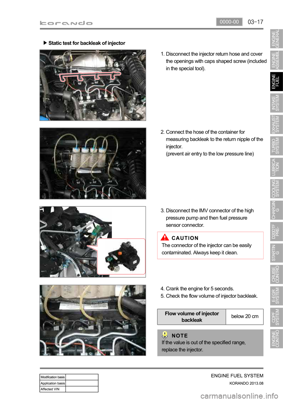
Static test for backleak of injector
Disconnect the injector return hose and cover
the openings with caps shaped screw (included
in the special tool). 1.
Connect the hose of the container for
measuring backleak to the return nipple of the
injector.
(prevent air entry to the low pressure line) 2.
Disconnect the IMV connector of the high
pressure pump and then fuel pressure
sensor connector. 3.
The connector of the injector can be easily
contaminated. Always keep it clean.
Crank the engine for 5 seconds.
Check the flow volume of injector backleak. 4.
5.
If the value is out of the specified range,
replace the injector.
Flow volume of injector
backleakbelow 20 cm
Page 244 of 1336
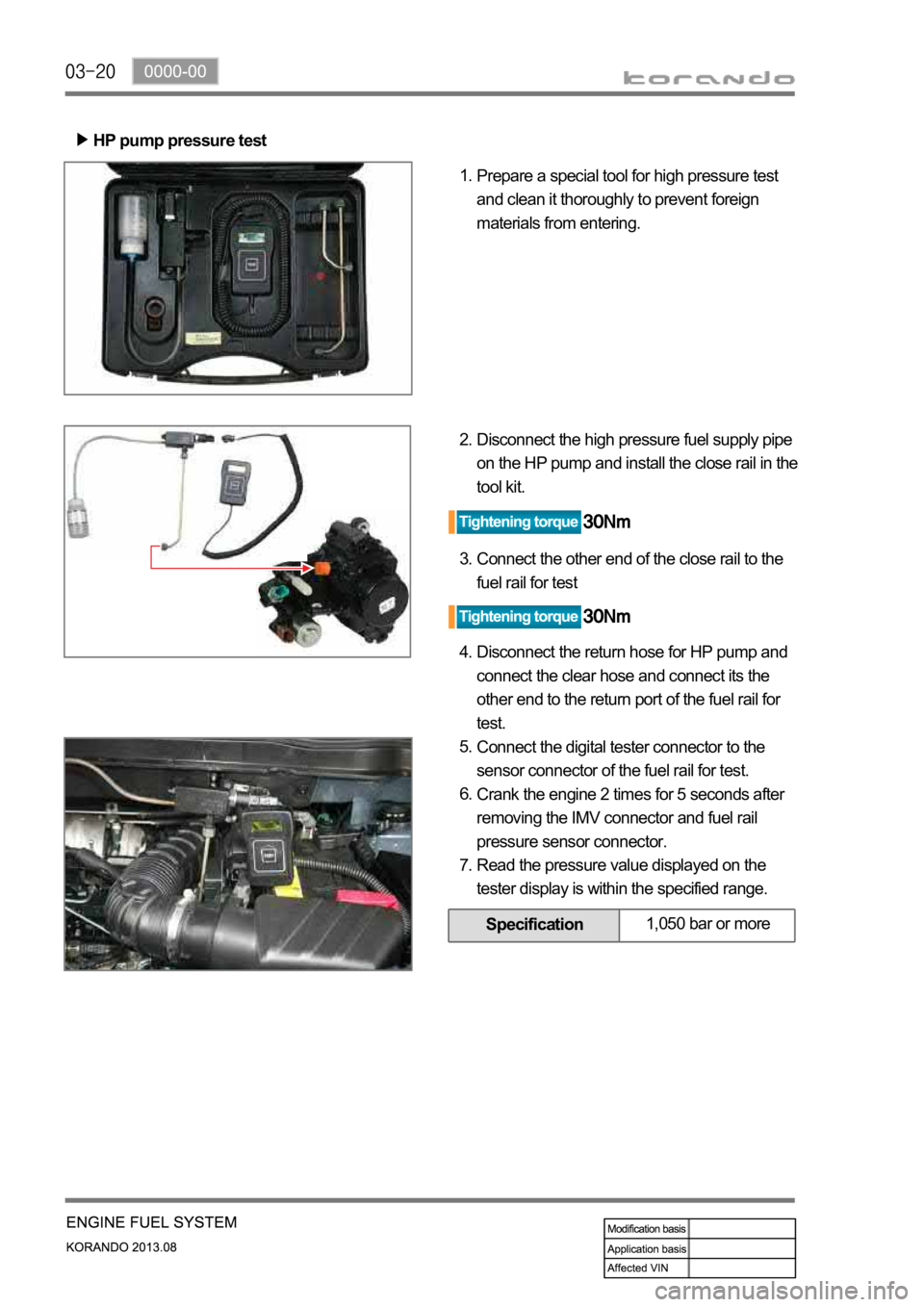
HP pump pressure test
Prepare a special tool for high pressure test
and clean it thoroughly to prevent foreign
materials from entering. 1.
Disconnect the high pressure fuel supply pipe
on the HP pump and install the close rail in the
tool kit. 2.
Connect the other end of the close rail to the
fuel rail for test 3.
Disconnect the return hose for HP pump and
connect the clear hose and connect its the
other end to the return port of the fuel rail for
test. 4.
Connect the digital tester connector to the
sensor connector of the fuel rail for test.
Crank the engine 2 times for 5 seconds after
removing the IMV connector and fuel rail
pressure sensor connector.
Read the pressure value displayed on the
tester display is within the specified range. 5.
6.
7.
Specification1,050 bar or more
Page 248 of 1336
ENGINE CONTROL
SYSTEM
Engine ECU (D20DTF)
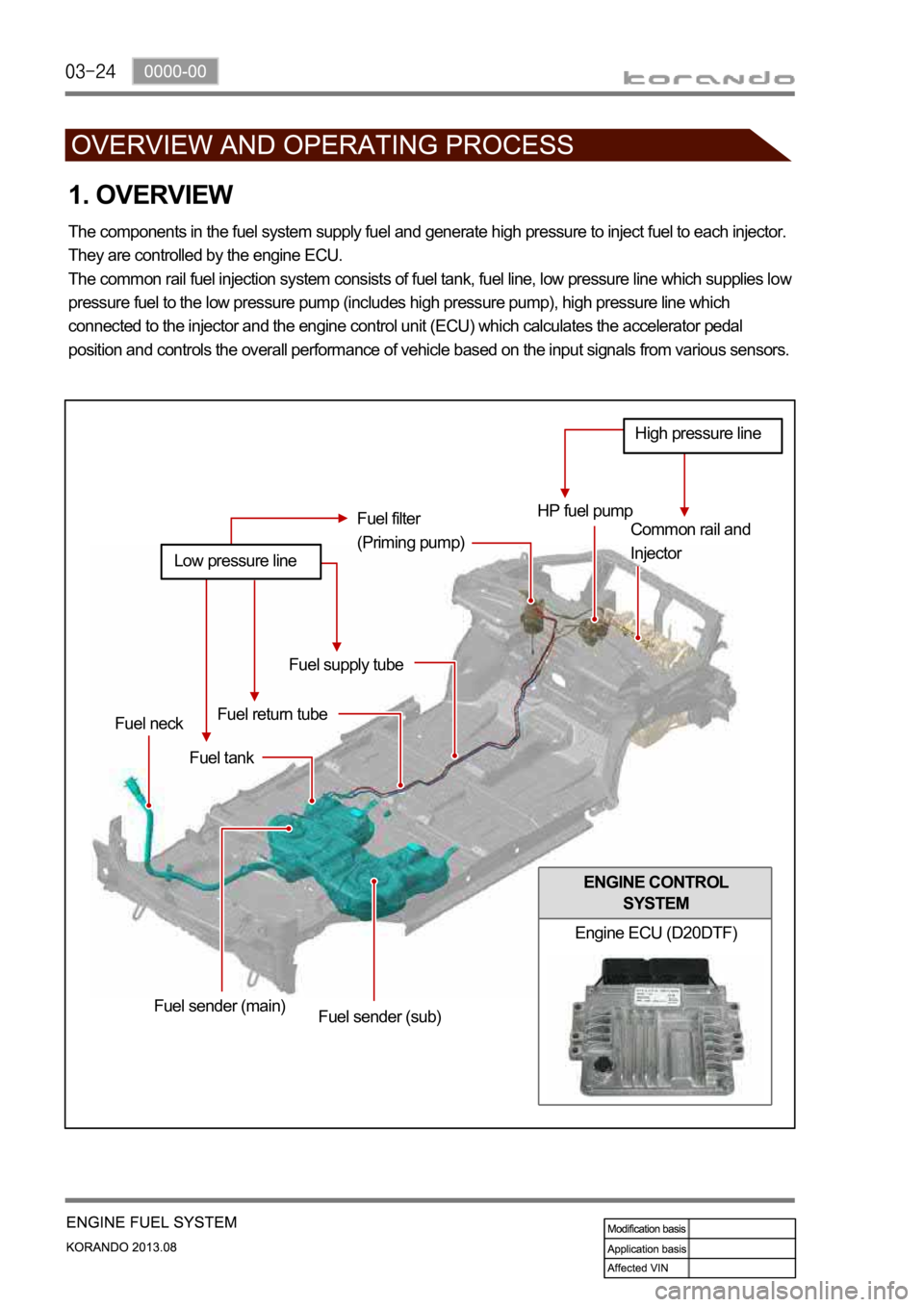
1. OVERVIEW
The components in the fuel system supply fuel and generate high pressure to inject fuel to each injector.
They are controlled by the engine ECU.
The common rail fuel injection system consists of fuel tank, fuel line, low pressure line which supplies lo
w
pressure fuel to the low pressure pump (includes high pressure pump), high pressure line which
connected to the injector and the engine control unit (ECU) which calculates the accelerator pedal
position and controls the overall performance of vehicle based on the input signals from various sensors.
HP fuel pump
Common rail and
Injector Fuel filter
(Priming pump)
Fuel supply tube
Fuel return tube
Fuel tank Fuel neck
Fuel sender (main)
Fuel sender (sub)
Low pressure line
High pressure line
Page 250 of 1336
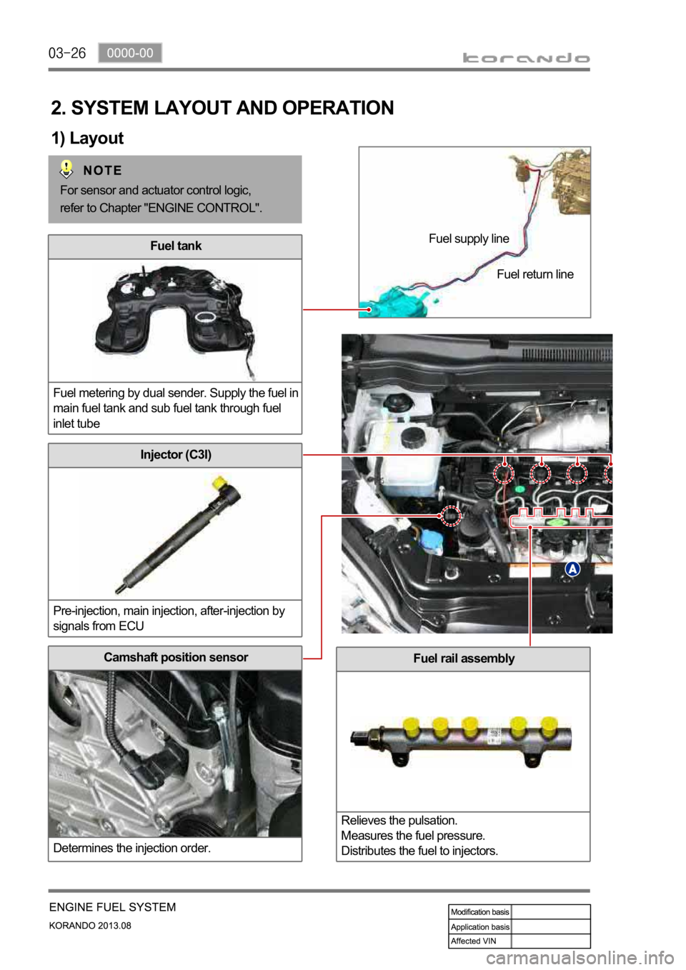
Fuel rail assembly
Relieves the pulsation.
Measures the fuel pressure.
Distributes the fuel to injectors.Camshaft position sensor
Determines the injection order.
Injector (C3I)
Pre-injection, main injection, after-injection by
signals from ECU
Fuel tank
Fuel metering by dual sender. Supply the fuel in
main fuel tank and sub fuel tank through fuel
inlet tube
2. SYSTEM LAYOUT AND OPERATION
1) Layout
Fuel supply line
Fuel return line
For sensor and actuator control logic,
refer to Chapter "ENGINE CONTROL".
Page 251 of 1336
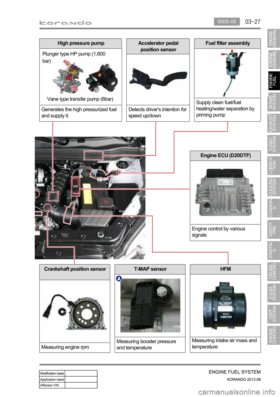
0000-00
Crankshaft position sensor
Measuring engine rpmT-MAP sensor
Measuring booster pressure
and temperatureHFM
Measuring intake air mass and
temperature
Engine ECU (D20DTF)
Engine control by various
signals
High pressure pump
Generates the high pressurized fuel
and supply it.
Plunger type HP pump (1,800
bar)
Vane type transfer pump (6bar)
Accelerator pedal
position sensor
Detects driver's intention for
speed up/downFuel filter assembly
Supply clean fuel/fuel
heating/water separation by
priming pump
Page 252 of 1336
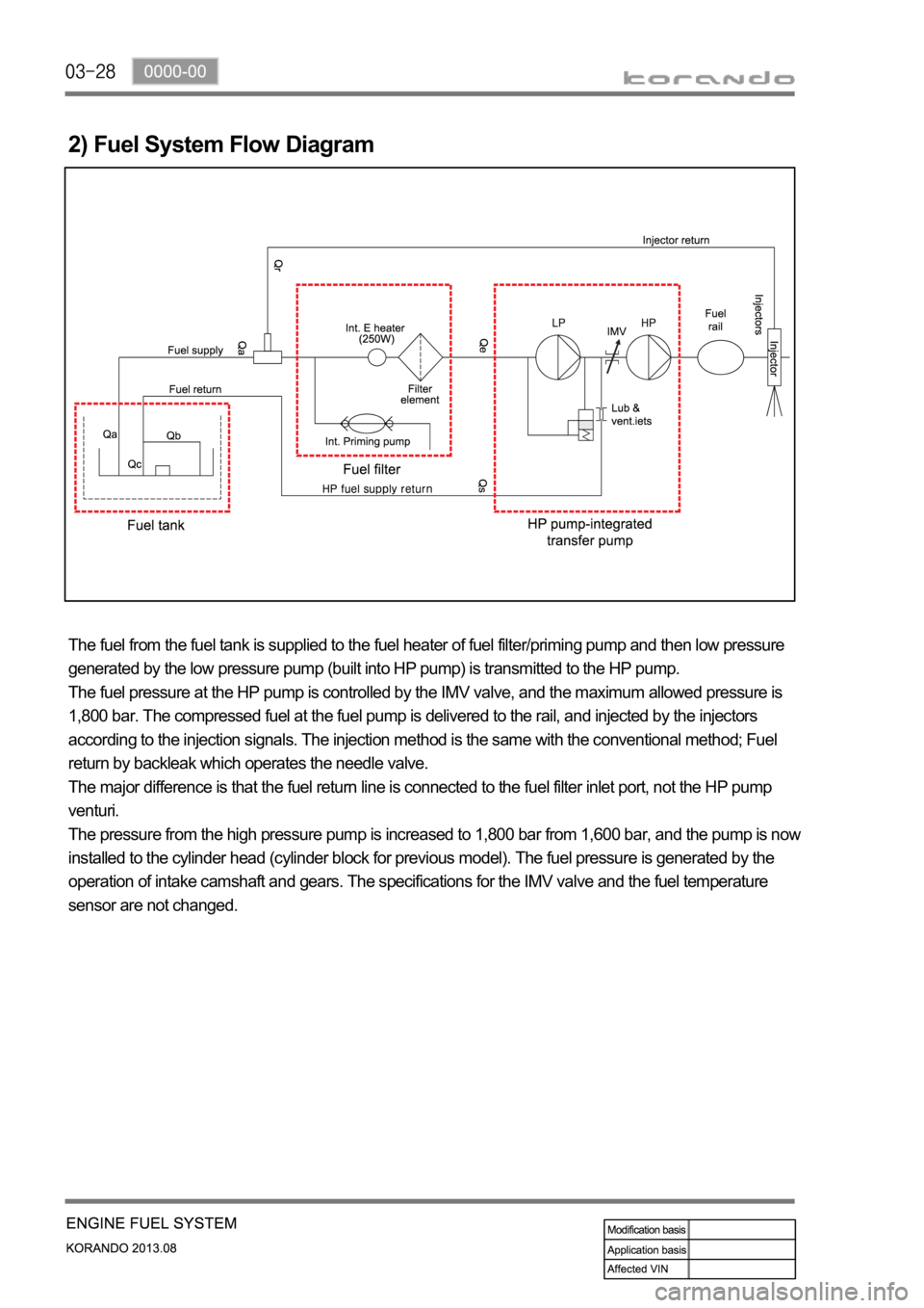
2) Fuel System Flow Diagram
The fuel from the fuel tank is supplied to the fuel heater of fuel filter/priming pump and then low pressure
generated by the low pressure pump (built into HP pump) is transmitted to the HP pump.
The fuel pressure at the HP pump is controlled by the IMV valve, and the maximum allowed pressure is
1,800 bar. The compressed fuel at the fuel pump is delivered to the rail, and injected by the injectors
according to the injection signals. The injection method is the same with the conventional method; Fuel
return by backleak which operates the needle valve.
The major difference is that the fuel return line is connected to the fuel filter inlet port, not the HP pump
venturi.
The pressure from the high pressure pump is increased to 1,800 bar from 1,600 bar, and the pump is now
installed to the cylinder head (cylinder block for previous model). The fuel pressure is generated by the
operation of intake camshaft and gears. The specifications for the IMV valve and the fuel temperature
sensor are not changed.
Page 254 of 1336
The engine ECU calculates the accelerator pedal based on the input signals from various sensors, and
controls the overall operation of the vehicle.
The ECU receives the signals from various sensor through data line, and performs effective air-fuel ratio
control based on these signals.
The crankshaft speed (position) sensor measures the engine speed, and the camshaft speed (position)
sensor determines the order of injections, and the ECU detects the amount of the accelerator pedal
depressed (driver's will) by receiving the electrical signals from the accelerator pedal sensor.
The mass air flow sensor detects the volume of intake air and sends the value to the ECU.
The major function of the ECU is controlling air-fuel ratio to reduce the emission level (EGR valve control)
by detecting instantaneous air flow change with the signals from the mass air flow sensor.
Also, the ECU uses the signals from the coolant temperature & air temperature sensors, booster pressure
sensor, atmospheric pressure sensor to: a) determine injection starting point and set value for pilot
injection, and b) deal with various operations and variable conditions.
Page 260 of 1336
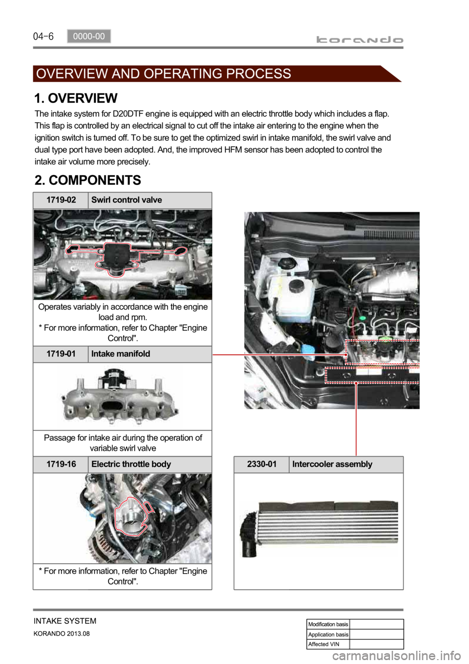
1719-02 Swirl control valve
Operates variably in accordance with the engine
load and rpm.
* For more information, refer to Chapter "Engine
Control".
1719-01 Intake manifold
Passage for intake air during the operation of
variable swirl valve
1719-16 Electric throttle body
* For more information, refer to Chapter "Engine
Control".
1. OVERVIEW
The intake system for D20DTF engine is equipped with an electric throttle body which includes a flap.
This flap is controlled by an electrical signal to cut off the intake air entering to the engine when the
ignition switch is turned off. To be sure to get the optimized swirl in intake manifold, the swirl valve and
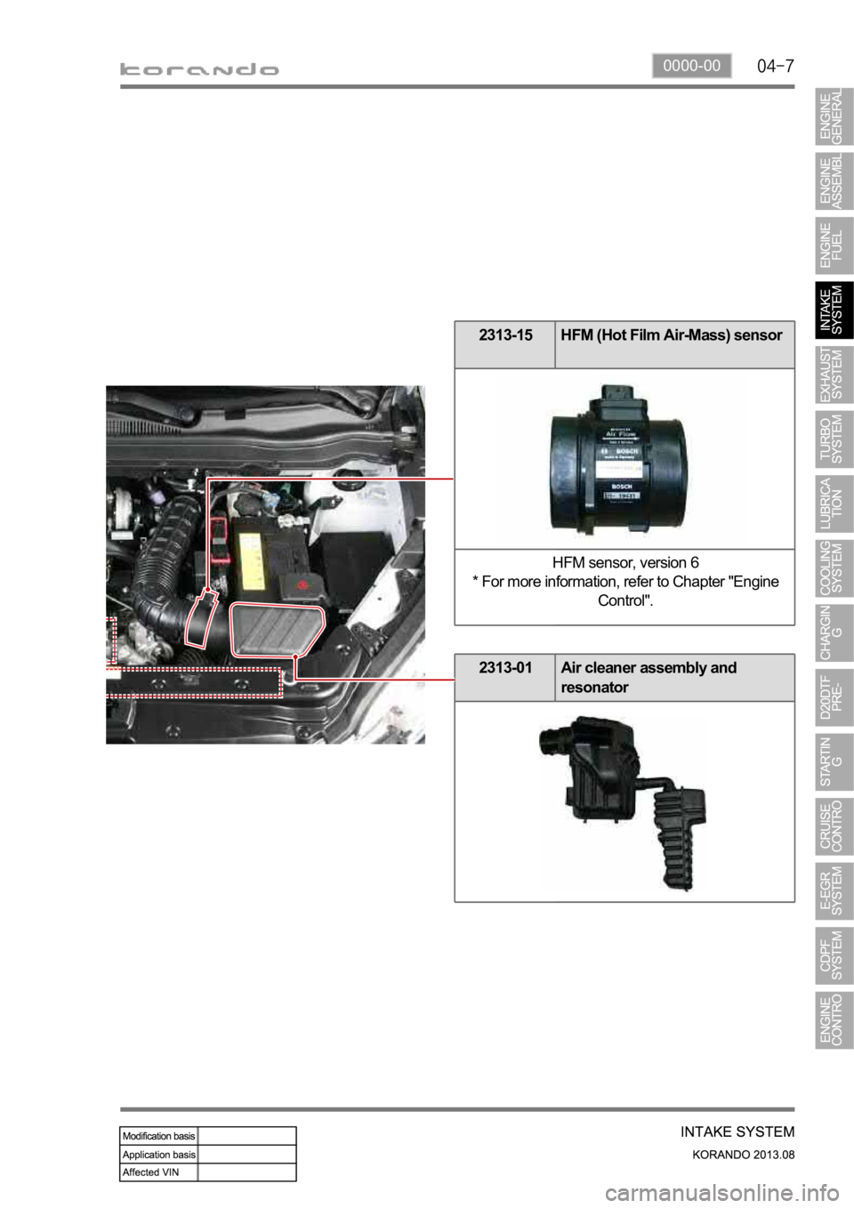
dual type port have been adopted. And, the improved HFM sensor has been adopted to control the
intake air volume more precisely.
2. COMPONENTS
2330-01 Intercooler assembly
Page 261 of 1336
0000-00
2313-15 HFM (Hot Film Air-Mass) sensor
HFM sensor, version 6
* For more information, refer to Chapter "Engine
Control".
2313-01 Air cleaner assembly and
resonator
Page 273 of 1336
0000-00
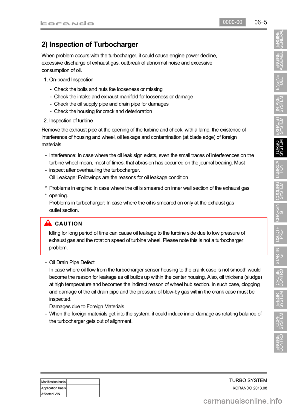
2) Inspection of Turbocharger
On-board Inspection 1.
Check the bolts and nuts foe looseness or missing
Check the intake and exhaust manifold for looseness or damage
Check the oil supply pipe and drain pipe for damages
Check the housing for crack and deterioration -
-
-
-
Inspection of turbine 2.
Remove the exhaust pipe at the opening of the turbine and check, with a lamp, the existence of
interference of housing and wheel, oil leakage and contamination (at blade edge) of foreign
materials.
Interference: In case where the oil leak sign exists, even the small traces of interferences on the
turbine wheel mean, most of times, that abrasion has occurred on the journal bearing. Must
inspect after overhauling the turbocharger.
Oil Leakage: Followings are the reasons for oil leakage condition -
-
Problems in engine: In case where the oil is smeared on inner wall section of the exhaust gas
opening.
Problems in turbocharger: In case where the oil is smeared on only at the exhaust gas
outlet section. *
* When problem occurs with the turbocharger, it could cause engine power decline,
excessive discharge of exhaust gas, outbreak of abnormal noise and excessive
consumption of oil.
Idling for long period of time can cause oil leakage to the turbine side due to low pressure of
exhaust gas and the rotation speed of turbine wheel. Please note this is not a turbocharger
problem.
Oil Drain Pipe Defect
In case where oil flow from the turbocharger sensor housing to the crank case is not smooth would
become the reason for leakage as oil builds up within the center housing. Also, oil thickens (sludge)
at high temperature and becomes the indirect reason of wheel hub section. In such case, clogging
and damage of the oil drain pipe and the pressure of blow-by gas within the crank case must be
inspected.
Damages due to Foreign Materials
When the foreign materials get into the system, it could induce inner damage as rotating balance of
the turbocharger gets out of alignment. -
-