tightening SSANGYONG KORANDO 2013 Service Manual
[x] Cancel search | Manufacturer: SSANGYONG, Model Year: 2013, Model line: KORANDO, Model: SSANGYONG KORANDO 2013Pages: 1336, PDF Size: 92.18 MB
Page 188 of 1336
0000-00
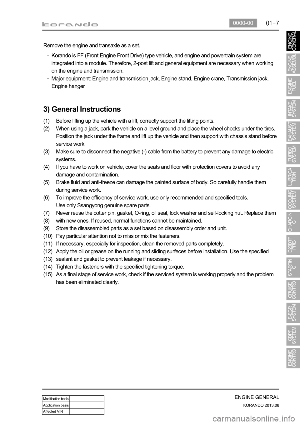
3) General Instructions
Before lifting up the vehicle with a lift, correctly support the lifting points.
When using a jack, park the vehicle on a level ground and place the wheel chocks under the tires.
Position the jack under the frame and lift up the vehicle and then support with chassis stand before
service work.
Make sure to disconnect the negative (-) cable from the battery to prevent any damage to electric
systems.
If you have to work on vehicle, cover the seats and floor with protection covers to avoid any
damage and contamination.
Brake fluid and anti-freeze can damage the painted surface of body. So carefully handle them
during service work.
To improve the efficiency of service work, use only recommended and specified tools.
Use only Ssangyong genuine spare parts.
Never reuse the cotter pin, gasket, O-ring, oil seal, lock washer and self-locking nut. Replace them
with new ones. If reused, normal functions cannot be maintained.
Store the disassembled parts as a set based on disassembly order and unit.
Pay particular attention not to miss or mix the fasteners.
If necessary, especially for inspection, clean the removed parts completely.
Apply the oil or grease on the running and sliding surfeces before installation. Use the specified
sealant and gasket to prevent leakage if necessary.
Tighten the fasteners with the specified tightening torque.
As a final stage of service work, check if the serviced system is working properly and the problem
has been eliminated clearly. (1)
(2)
(3)
(4)
(5)
(6)
(7)
(8)
(9)
(10)
(11)
(12)
(13)
(14)
(15) Remove the engine and transaxle as a set.
Korando is FF (Front Engine Front Drive) type vehicle, and engine and powertrain system are
integrated into a module. Therefore, 2-post lift and general equipment are necessary when working
on the engine and transmission.
Major equipment: Engine and transmission jack, Engine stand, Engine crane, Transmission jack,
Engine hanger -
-
Page 190 of 1336
0000-00
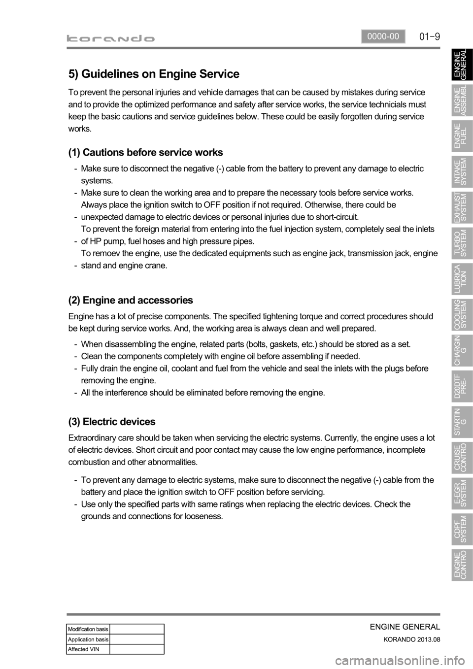
5) Guidelines on Engine Service
(1) Cautions before service works
Make sure to disconnect the negative (-) cable from the battery to prevent any damage to electric
systems.
Make sure to clean the working area and to prepare the necessary tools before service works.
Always place the ignition switch to OFF position if not required. Otherwise, there could be
unexpected damage to electric devices or personal injuries due to short-circuit.
To prevent the foreign material from entering into the fuel injection system, completely seal the inlets
of HP pump, fuel hoses and high pressure pipes.
To remoev the engine, use the dedicated equipments such as engine jack, transmission jack, engine
stand and engine crane. -
-
-
-
-
(2) Engine and accessories
When disassembling the engine, related parts (bolts, gaskets, etc.) should be stored as a set.
Clean the components completely with engine oil before assembling if needed.
Fully drain the engine oil, coolant and fuel from the vehicle and seal the inlets with the plugs before
removing the engine.
All the interference should be eliminated before removing the engine. -
-
-
-
(3) Electric devices
To prevent any damage to electric systems, make sure to disconnect the negative (-) cable from the
battery and place the ignition switch to OFF position before servicing.
Use only the specified parts with same ratings when replacing the electric devices. Check the
grounds and connections for looseness. -
- To prevent the personal injuries and vehicle damages that can be caused by mistakes during service
and to provide the optimized performance and safety after service works, the service technicials must
keep the basic cautions and service guidelines below. These could be easily forgotten during service
works.
Engine has a lot of precise components. The specified tightening torque and correct procedures should
be kept during service works. And, the working area is always clean and well prepared.
Extraordinary care should be taken when servicing the electric systems. Currently, the engine uses a lot
of electric devices. Short circuit and poor contact may cause the low engine performance, incomplete
combustion and other abnormalities.
Page 193 of 1336
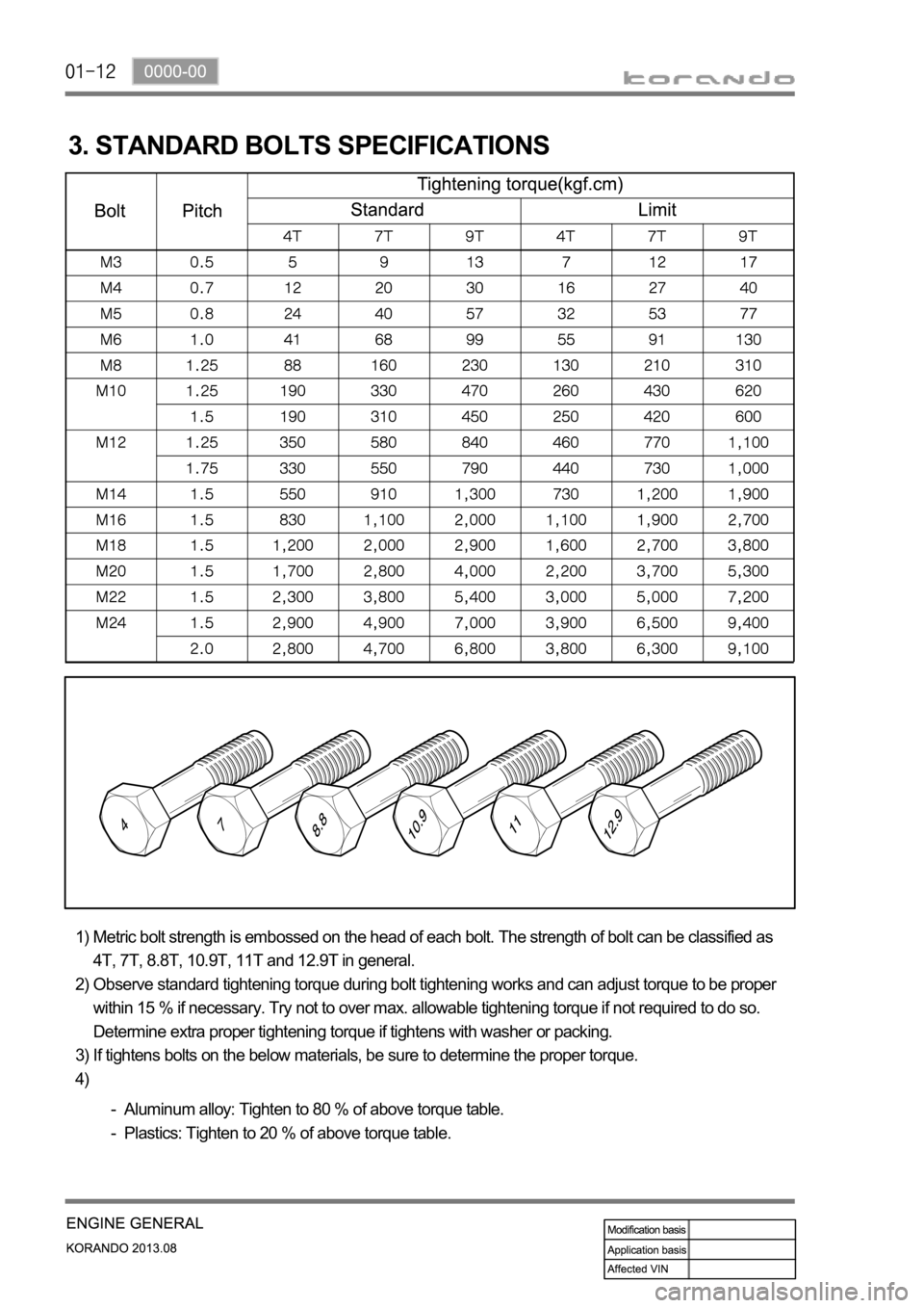
3. STANDARD BOLTS SPECIFICATIONS
Metric bolt strength is embossed on the head of each bolt. The strength of bolt can be classified as
4T, 7T, 8.8T, 10.9T, 11T and 12.9T in general.
Observe standard tightening torque during bolt tightening works and can adjust torque to be proper
within 15 % if necessary. Try not to over max. allowable tightening torque if not required to do so.
Determine extra proper tightening torque if tightens with washer or packing.
If tightens bolts on the below materials, be sure to determine the proper torque. 1)
2)
3)
4)
Aluminum alloy: Tighten to 80 % of above torque table.
Plastics: Tighten to 20 % of above torque table. -
-
Page 200 of 1336
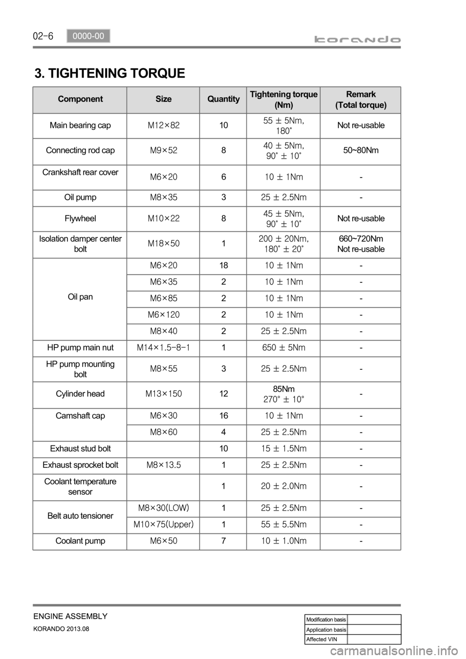
3. TIGHTENING TORQUE
Component Size QuantityTightening torque
(Nm)Remark
(Total torque)
Main bearing cap
10Not re-usable
Connecting rod cap
850~80Nm
Crankshaft rear cover
6-
Oil pump
3-
Flywheel
8Not re-usable
Isolation damper center
bolt
1660~720Nm
Not re-usable
Oil pan
18-
2-
2-
2-
2-
HP pump main nut
1-
HP pump mounting
bolt
3-
Cylinder head
1285Nm-
Camshaft cap
16-
4-
Exhaust stud bolt 10
-
Exhaust sprocket bolt
1-
Coolant temperature
sensor1-
Belt auto tensioner
1-
1-
Coolant pump
7-
Page 201 of 1336
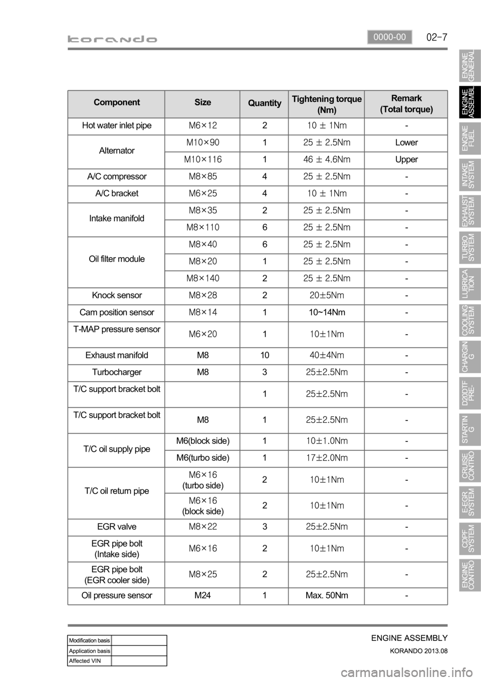
0000-00
Knock sensor2-
Cam position sensor
1 10~14Nm -
T-MAP pressure sensor
1-
Exhaust manifold M8 10
-
Turbocharger M8 3
-
T/C support bracket bolt
1
-
T/C support bracket bolt
M8 1
-
T/C oil supply pipeM6(block side) 1
-
M6(turbo side) 1
-
T/C oil return pipe
(turbo side)2-
(block side)2-
EGR valve
3-
EGR pipe bolt
(Intake side)
2-
EGR pipe bolt
(EGR cooler side)
2-
Oil pressure sensor M24 1 Max. 50Nm -
Component Size
QuantityTightening torque
(Nm)Remark
(Total torque)
Hot water inlet pipe
2-
Alternator
1Lower
1Upper
A/C compressor
4-
A/C bracket
4-
Intake manifold
2-
6-
Oil filter module
6-
1-
2-
Page 202 of 1336
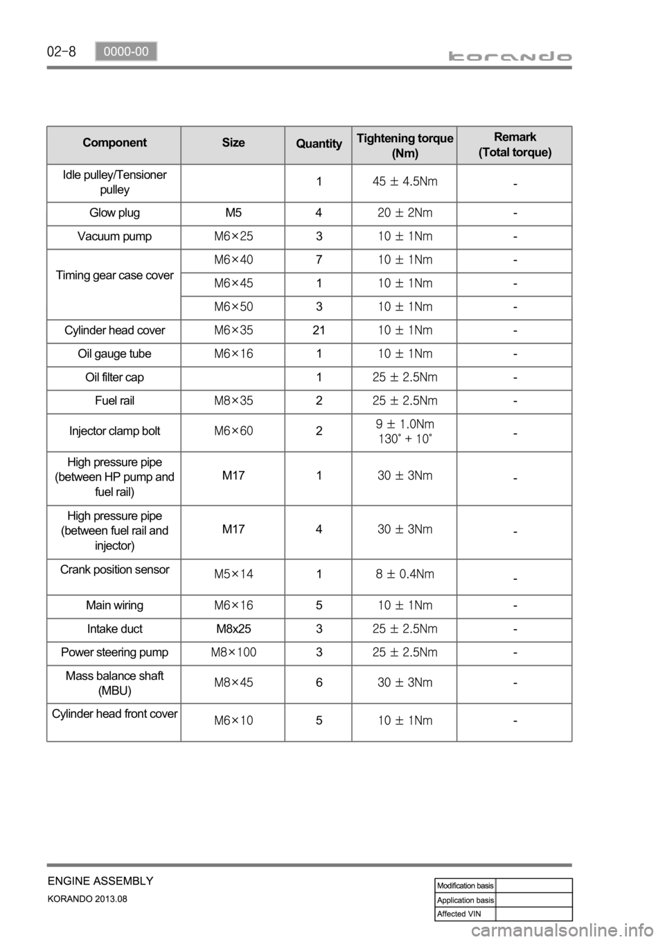
Oil gauge tube1-
Oil filter cap 1
-
Fuel rail
2-
Injector clamp bolt
2-
High pressure pipe
(between HP pump and
fuel rail)M17 1
-
High pressure pipe
(between fuel rail and
injector)M17 4
-
Crank position sensor
1-
Main wiring
5-
Intake duct M8x25 3
-
Power steering pump
3-
Mass balance shaft
(MBU)
6-
Cylinder head front cove
r5-
Timing gear case cover
7-
1-
3-
Cylinder head cover
21-
Component Size
QuantityTightening torque
(Nm)Remark
(Total torque)
Idle pulley/Tensioner
pulley1
-
Glow plug M5 4
-
Vacuum pump
3-
Page 210 of 1336
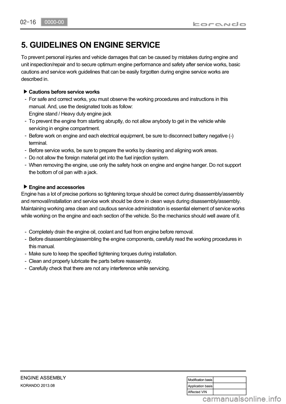
5. GUIDELINES ON ENGINE SERVICE
To prevent personal injuries and vehicle damages that can be caused by mistakes during engine and
unit inspection/repair and to secure optimum engine performance and safety after service works, basic
cautions and service work guidelines that can be easily forgotten during engine service works are
described in.
Cautions before service works
For safe and correct works, you must observe the working procedures and instructions in this
manual. And, use the designated tools as follow:
Engine stand / Heavy duty engine jack
To prevent the engine from starting abruptly, do not allow anybody to get in the vehicle while
servicing in engine compartment.
Before work on engine and each electrical equipment, be sure to disconnect battery negative (-)
terminal.
Before service works, be sure to prepare the works by cleaning and aligning work areas.
Do not allow the foreign material get into the fuel injection system.
When removing the engine, use only the safety hook on engine and engine hanger. Do not support
the bottom of oil pan with a jack.
Engine and accessories
-
-
-
-
-
-
Completely drain the engine oil, coolant and fuel from engine before removal.
Before disassembling/assembling the engine components, carefully read the working procedures in
this manual.
Make sure to keep the specified tightening torques during installation.
Clean and properly lubricate the parts before reassembly.
Carefully check that there are not any interference while servicing. -
-
-
-
- Engine has a lot of precise portions so tightening torque should be correct during disassembly/assembly
and removal/installation and service work should be done in clean ways during disassembly/assembly.
Maintaining working area clean and cautious service administration is essential element of service works
while working on the engine and each section of the vehicle. So the mechanics should well aware of it.
Page 230 of 1336
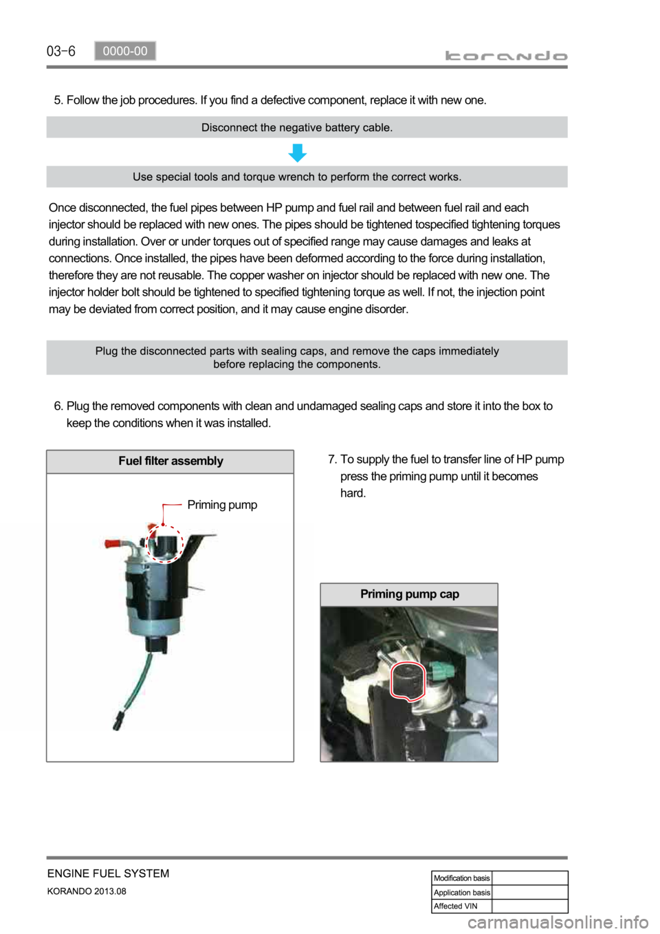
Fuel filter assembly
Follow the job procedures. If you find a defective component, replace it with new one. 5.
Once disconnected, the fuel pipes between HP pump and fuel rail and between fuel rail and each
injector should be replaced with new ones. The pipes should be tightened tospecified tightening torques
during installation. Over or under torques out of specified range may cause damages and leaks at
connections. Once installed, the pipes have been deformed according to the force during installation,
therefore they are not reusable. The copper washer on injector should be replaced with new one. The
injector holder bolt should be tightened to specified tightening torque as well. If not, the injection point
may be deviated from correct position, and it may cause engine disorder.
Plug the removed components with clean and undamaged sealing caps and store it into the box to
keep the conditions when it was installed. 6.
To supply the fuel to transfer line of HP pump
press the priming pump until it becomes
hard. 7.
Priming pump
Priming pump cap
Page 299 of 1336
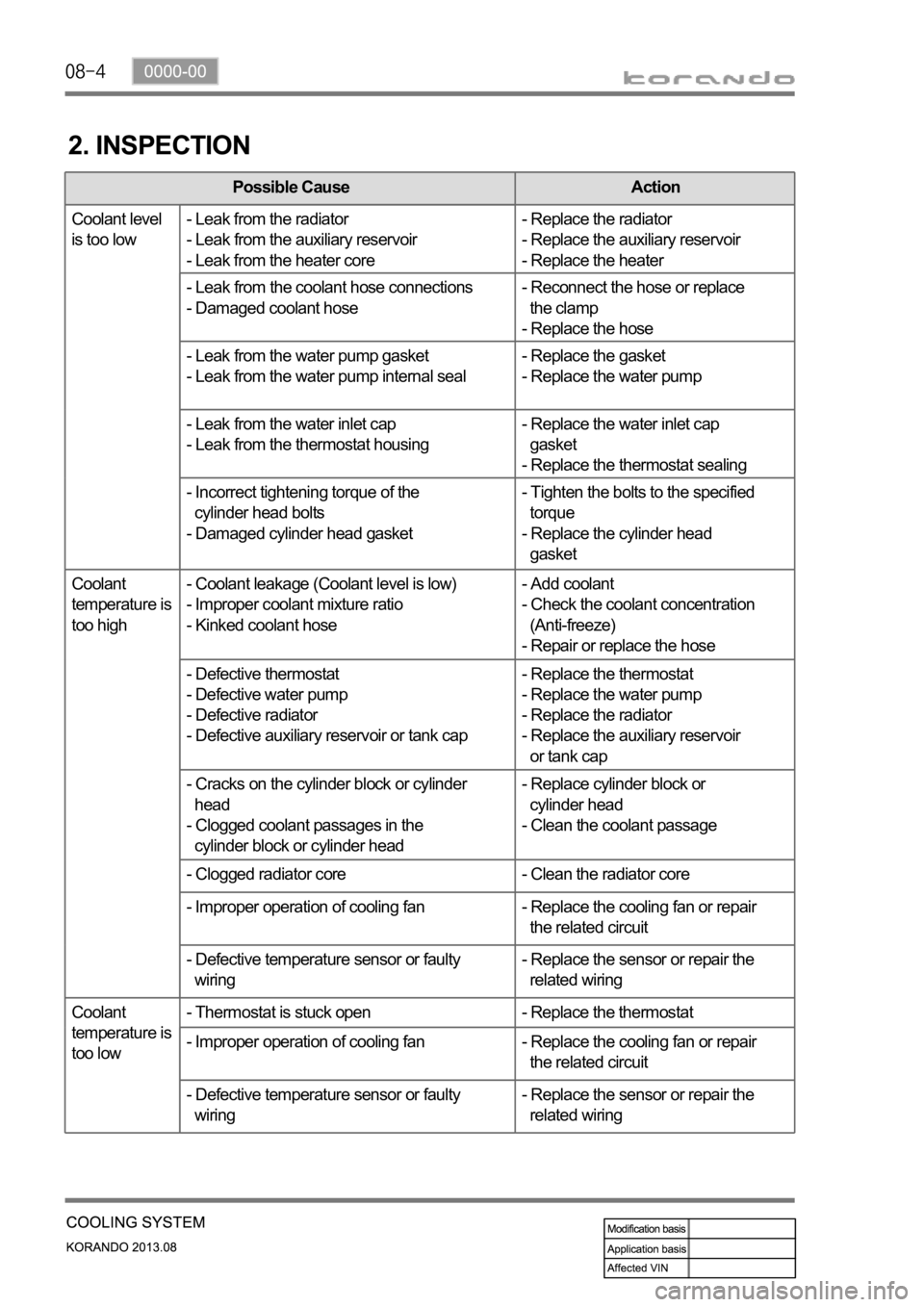
2. INSPECTION
Possible Cause Action
Coolant level
is too low- Leak from the radiator
- Leak from the auxiliary reservoir
- Leak from the heater core- Replace the radiator
- Replace the auxiliary reservoir
- Replace the heater
- Leak from the coolant hose connections
- Damaged coolant hose- Reconnect the hose or replace
the clamp
- Replace the hose
- Leak from the water pump gasket
- Leak from the water pump internal seal- Replace the gasket
- Replace the water pump
- Leak from the water inlet cap
- Leak from the thermostat housing- Replace the water inlet cap
gasket
- Replace the thermostat sealing
- Incorrect tightening torque of the
cylinder head bolts
- Damaged cylinder head gasket- Tighten the bolts to the specified
torque
- Replace the cylinder head
gasket
Coolant
temperature is
too high- Coolant leakage (Coolant level is low)
- Improper coolant mixture ratio
- Kinked coolant hose- Add coolant
- Check the coolant concentration
(Anti-freeze)
- Repair or replace the hose
- Defective thermostat
- Defective water pump
- Defective radiator
- Defective auxiliary reservoir or tank cap- Replace the thermostat
- Replace the water pump
- Replace the radiator
- Replace the auxiliary reservoir
or tank cap
- Cracks on the cylinder block or cylinder
head
- Clogged coolant passages in the
cylinder block or cylinder head- Replace cylinder block or
cylinder head
- Clean the coolant passage
- Clogged radiator core - Clean the radiator core
- Improper operation of cooling fan - Replace the cooling fan or repair
the related circuit
- Defective temperature sensor or faulty
wiring- Replace the sensor or repair the
related wiring
Coolant
temperature is
too low- Thermostat is stuck open - Replace the thermostat
- Improper operation of cooling fan - Replace the cooling fan or repair
the related circuit
- Defective temperature sensor or faulty
wiring- Replace the sensor or repair the
related wiring
Page 321 of 1336

GCU (Glow plug Control Unit)
2. TIGHTENING TORQUE
No. Name Tightening torque
1 Glow plug
2 Glow plug control unit bolt
Glow plug