battery SSANGYONG MUSSO 2003 Service Manual
[x] Cancel search | Manufacturer: SSANGYONG, Model Year: 2003, Model line: MUSSO, Model: SSANGYONG MUSSO 2003Pages: 1574, PDF Size: 26.41 MB
Page 1306 of 1574
9U-10 CONTROL UNITS AND SYSTEMMAINTENANCE AND REPAIR
ON-VEHICLE SERVICE
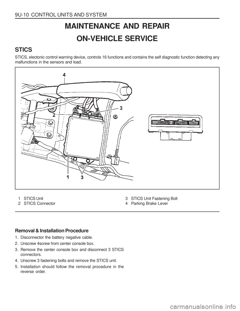
STICS STICS, electonic control warning device, controls 16 functions and contains the self diagnostic function detecting any malfunctions in the sensors and load. Removal & Installation Procedure
1. Disconnector the battery negative cable.
2. Unscrew 4screw from center console box.
3. Remove the center console box and disconnect 3 STICS connectors.
4. Unscrew 3 fastening bolts and remove the STICS unit.
5. Installation should follow the removal procedure in the reverse order.
1 STICS Unit
2 STICS Connector 3 STICS Unit Fastening Bolt
4 Parking Brake Lever
Page 1317 of 1574
MUSSO-SPORTS 1A-5
SUPPLEMENT
KAA5A020
KAA5A020
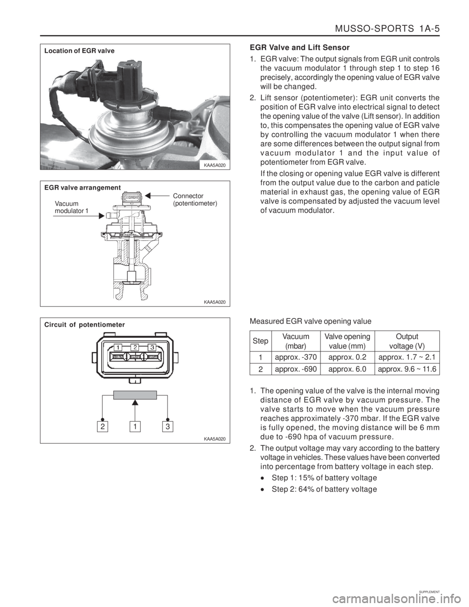
KAA5A020EGR Valve and Lift Sensor
1. EGR valve: The output signals from EGR unit controls
the vacuum modulator 1 through step 1 to step 16 precisely, accordingly the opening value of EGR valvewill be changed.
2. Lift sensor (potentiometer): EGR unit converts the position of EGR valve into electrical signal to detectthe opening value of the valve (Lift sensor). In additionto, this compensates the opening value of EGR valveby controlling the vacuum modulator 1 when thereare some differences between the output signal fromvacuum modulator 1 and the input value ofpotentiometer from EGR valve. If the closing or opening value EGR valve is different from the output value due to the carbon and paticlematerial in exhaust gas, the opening value of EGRvalve is compensated by adjusted the vacuum levelof vacuum modulator.
Measured EGR valve opening value Step 1 2
Vacuum(mbar)
approx. -370 approx. -690 Valve opening
value (mm)
approx. 0.2approx. 6.0 Output
voltage (V)
approx. 1.7 ~ 2.1
approx. 9.6 ~ 11.6
1. The opening value of the valve is the internal moving distance of EGR valve by vacuum pressure. The valve starts to move when the vacuum pressurereaches approximately -370 mbar. If the EGR valveis fully opened, the moving distance will be 6 mmdue to -690 hpa of vacuum pressure.
2. The output voltage may vary according to the battery voltage in vehicles. These values have been convertedinto percentage from battery voltage in each step.
Step 1: 15% of battery voltage
Step 2: 64% of battery voltage
Location of EGR valve EGR valve arrangement
Vacuum modulator 1 Connector (potentiometer)
Circuit of potentiometer
312
Page 1318 of 1574
1A-6 MUSSO-SPORTS
SUPPLEMENT
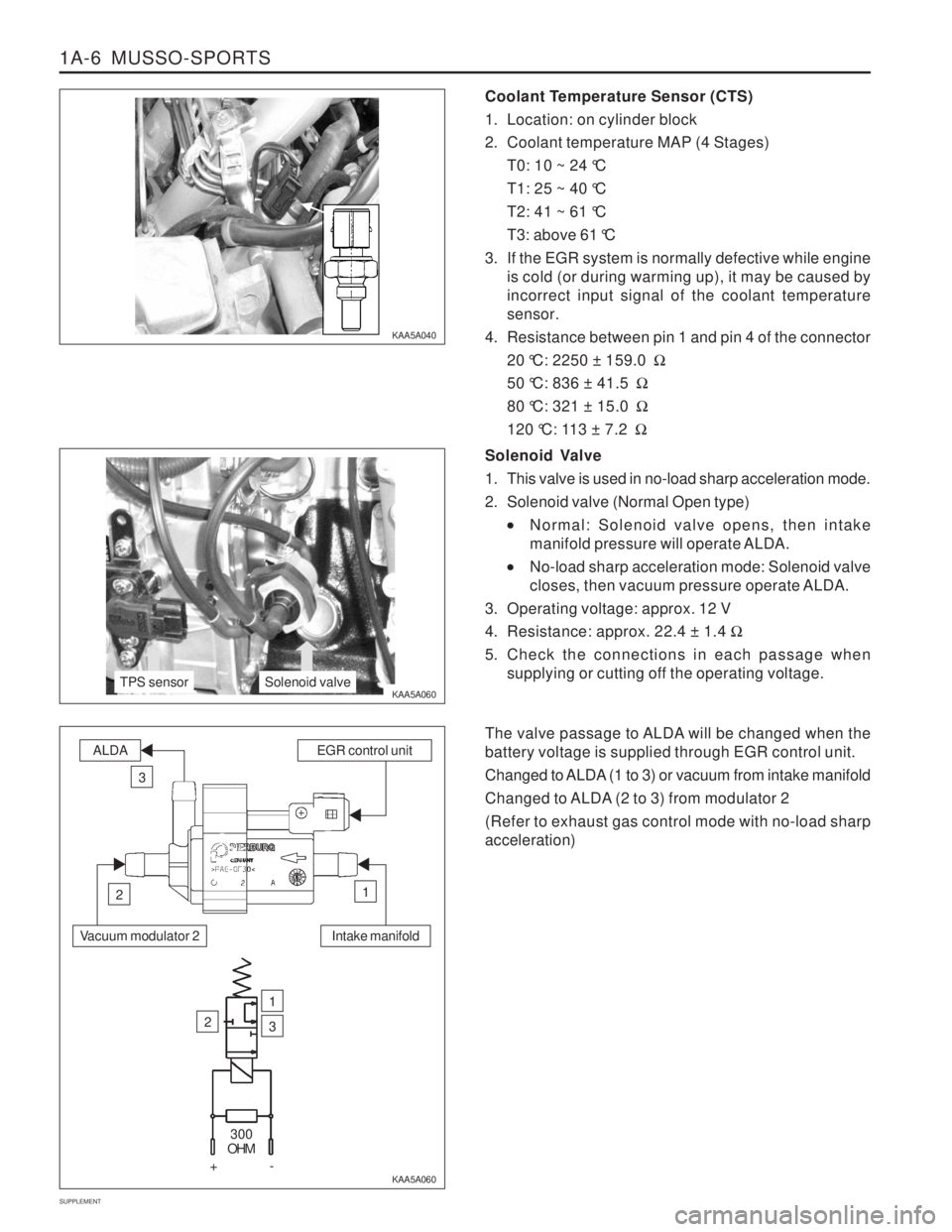
Coolant Temperature Sensor (CTS)
1. Location: on cylinder block
2. Coolant temperature MAP (4 Stages) T0: 10 ~ 24 °C
T1: 25 ~ 40 °C
T2: 41 ~ 61 °C
T3: above 61 °C
3. If the EGR system is normally defective while engine is cold (or during warming up), it may be caused by incorrect input signal of the coolant temperaturesensor.
4. Resistance between pin 1 and pin 4 of the connector 20 °C: 2250 ± 159.0 �
50 °C: 836 ± 41.5 �
80 °C: 321 ± 15.0 �
120 °C: 113 ± 7.2 �
KAA5A040 KAA5A060
KAA5A060Solenoid Valve
1. This valve is used in no-load sharp acceleration mode.
2. Solenoid valve (Normal Open type)
Normal: Solenoid valve opens, then intake
manifold pressure will operate ALDA.
No-load sharp acceleration mode: Solenoid valve
closes, then vacuum pressure operate ALDA.
3. Operating voltage: approx. 12 V
4. Resistance: approx. 22.4 ± 1.4 �
5. Check the connections in each passage when supplying or cutting off the operating voltage.
The valve passage to ALDA will be changed when the battery voltage is supplied through EGR control unit.
Changed to ALDA (1 to 3) or vacuum from intake manifold
Changed to ALDA (2 to 3) from modulator 2 (Refer to exhaust gas control mode with no-load sharp acceleration)
TPS sensorSolenoid valve
Intake manifold
ALDAEGR control unit
3
12
Vacuum modulator 2
2
1
3
300
OHM
+-
Page 1321 of 1574
MUSSO-SPORTS 1A-9
SUPPLEMENT
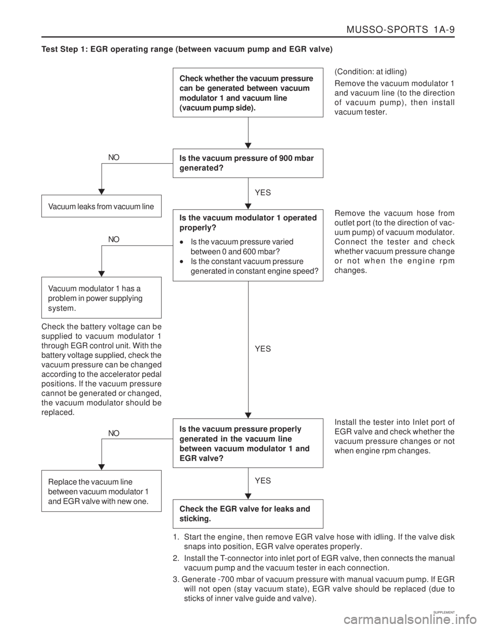
Test Step 1: EGR operating range (between vacuum pump and EGR valve)
(Condition: at idling) Remove the vacuum modulator 1 and vacuum line (to the directionof vacuum pump), then installvacuum tester.
Check whether the vacuum pressure can be generated between vacuum modulator 1 and vacuum line (vacuum pump side).
Is the vacuum pressure of 900 mbar generated?
Is the vacuum pressure properly generated in the vacuum line between vacuum modulator 1 and EGR valve?
Check the EGR valve for leaks and sticking.
Remove the vacuum hose from outlet port (to the direction of vac-uum pump) of vacuum modulator.Connect the tester and checkwhether vacuum pressure changeor not when the engine rpmchanges. Install the tester into Inlet port of EGR valve and check whether thevacuum pressure changes or notwhen engine rpm changes.
1. Start the engine, then remove EGR valve hose with idling. If the valve disk snaps into position, EGR valve operates properly.
2. Install the T-connector into inlet port of EGR valve, then connects the manual vacuum pump and the vacuum tester in each connection.
3. Generate -700 mbar of vacuum pressure with manual vacuum pump. If EGR will not open (stay vacuum state), EGR valve should be replaced (due tosticks of inner valve guide and valve).Vacuum leaks from vacuum line
NO
Is the vacuum modulator 1 operated properly?
Is the vacuum pressure varied
between 0 and 600 mbar?
Is the constant vacuum pressure
generated in constant engine speed?
Check the battery voltage can be supplied to vacuum modulator 1through EGR control unit. With thebattery voltage supplied, check thevacuum pressure can be changedaccording to the accelerator pedalpositions. If the vacuum pressurecannot be generated or changed,the vacuum modulator should bereplaced.
NO
Vacuum modulator 1 has a problem in power supplying system.
NO
Replace the vacuum line between vacuum modulator 1 and EGR valve with new one.
YES YES
YES
Page 1322 of 1574
1A-10 MUSSO-SPORTS
SUPPLEMENT
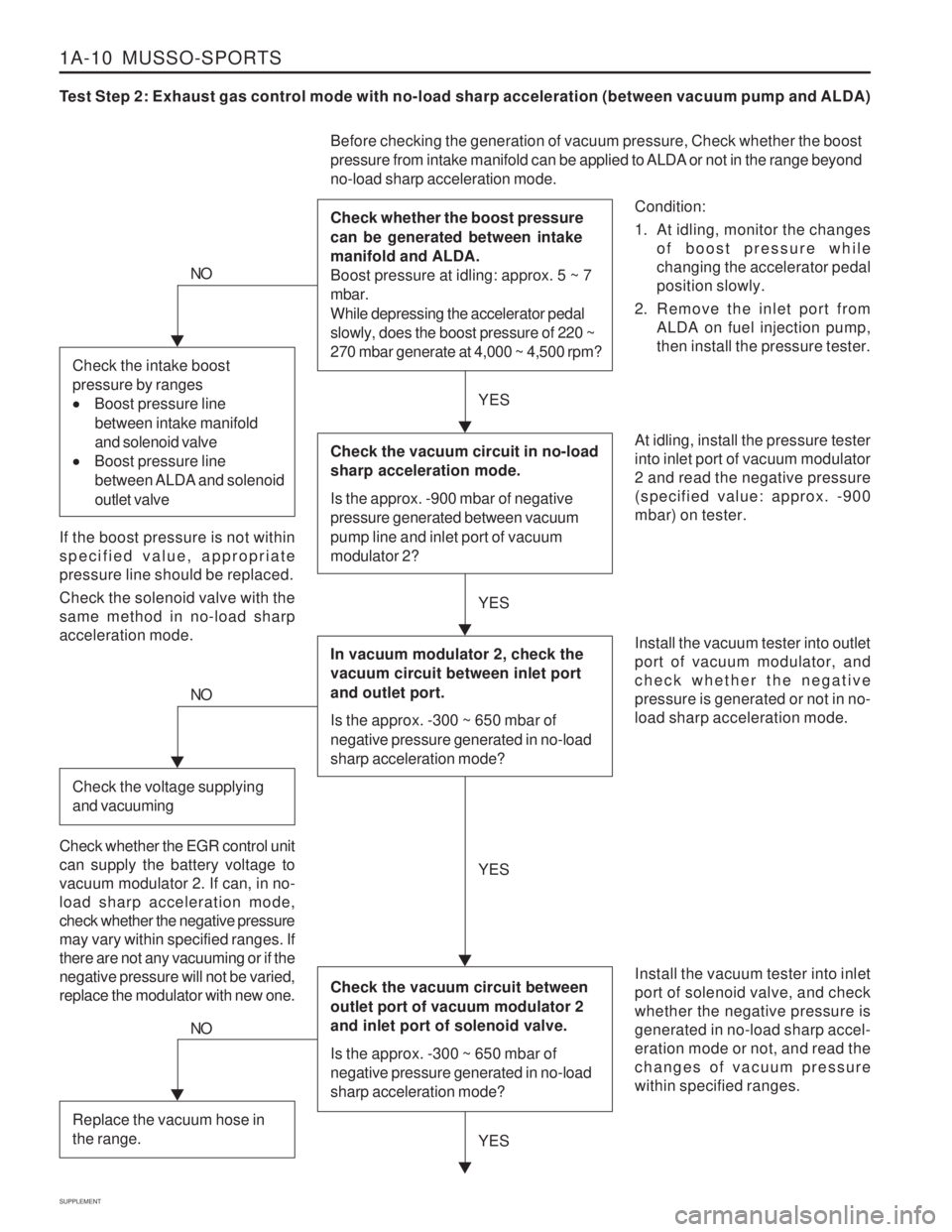
Test Step 2: Exhaust gas control mode with no-load sharp acceleration (between vacuum pump and ALDA)
Condition:
1. At idling, monitor the changesof boost pressure while changing the accelerator pedalposition slowly.
2. Remove the inlet port from ALDA on fuel injection pump,then install the pressure tester.
Before checking the generation of vacuum pressure, Check whether the boost
pressure from intake manifold can be applied to ALDA or not in the range beyond no-load sharp acceleration mode. Check whether the boost pressure can be generated between intake manifold and ALDA. Boost pressure at idling: approx. 5 ~ 7 mbar. While depressing the accelerator pedal slowly, does the boost pressure of 220 ~ 270 mbar generate at 4,000 ~ 4,500 rpm?
At idling, install the pressure tester into inlet port of vacuum modulator2 and read the negative pressure(specified value: approx. -900mbar) on tester. Install the vacuum tester into inlet port of solenoid valve, and checkwhether the negative pressure isgenerated in no-load sharp accel-eration mode or not, and read thechanges of vacuum pressurewithin specified ranges.
NO
If the boost pressure is not within specified value, appropriatepressure line should be replaced. Check the solenoid valve with the same method in no-load sharpacceleration mode.
YES
YES
Check the vacuum circuit in no-load sharp acceleration mode. Is the approx. -900 mbar of negative pressure generated between vacuum pump line and inlet port of vacuum modulator 2?
In vacuum modulator 2, check the vacuum circuit between inlet port and outlet port. Is the approx. -300 ~ 650 mbar of negative pressure generated in no-load sharp acceleration mode?
Check the vacuum circuit between outlet port of vacuum modulator 2 and inlet port of solenoid valve. Is the approx. -300 ~ 650 mbar of negative pressure generated in no-load sharp acceleration mode?
Install the vacuum tester into outlet port of vacuum modulator, andcheck whether the negativepressure is generated or not in no-load sharp acceleration mode.
Check the intake boost pressure by ranges
Boost pressure line
between intake manifold and solenoid valve
Boost pressure line
between ALDA and solenoid outlet valve
NO
Check the voltage supplying and vacuuming
Check whether the EGR control unit can supply the battery voltage tovacuum modulator 2. If can, in no-load sharp acceleration mode,check whether the negative pressuremay vary within specified ranges. Ifthere are not any vacuuming or if thenegative pressure will not be varied,replace the modulator with new one. YES
YES
NO
Replace the vacuum hose in the range.
Page 1350 of 1574
HOW TO USE ELECTRICAL WIRING DIAGRAM 1-3
Connector DiodeFuse in engine room fuse & relay box Fuse in passenger room fuse box Ground Joint - Inline wire connected point Splice pack(Junction connector)
C D
Ef F
G J
S
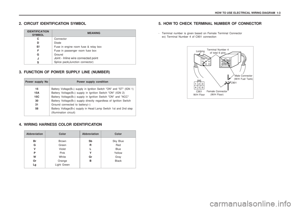
2. CIRCUIT IDENTIFICATION SYMBOL
3. FUNCTION OF POWER SUPPLY LINE (NUMBER)
IDENTIFICATION SYMBOL MEANING
Power supply No Power supply condition
Battery Voltage(B+) supply in Ignition Switch "ON" and "ST" (IGN 1)
Battery Voltage(B+) supply in Ignition Switch "ON" (IGN 2) Battery Voltage(B+) supply in Ignition Switch "ON" and "ACC"Battery Voltage(B+) supply directly regardless of Ignition Switch Ground connected to battery(
–)
Battery Voltage(B+) supply in Head Lamp Switch 1st and 2nd step
(Illumination circuit)
15
15A 15C
30 31 58
Abbreviation Color
BrownGreen Violet Pink
White
Orange
Light Green
Br
GV P
W
Or
LgAbbreviation Color
Sky BlueRed
Blue
Yellow
Gray
Black
Sb
RL Y
Gr B
4. WIRING HARNESS COLOR IDENTIFICATION 5. HOW TO CHECK
TERMINAL NUMBER OF CONNECTOR
- Terminal number is given based on Female Terminal Connector ex) Terminal Number 4 of C901 connection
Locking Terminal Number 4
of total 6 pins
Male Connector
(W/H Fuel Tank)
4 C901
Female Connector (W/H Floor)
C901
W/H Floor 13
2
46 5
Page 1366 of 1574
4-2 USAGE AND CAPACITY OF FUSES IN FUSE BOX
60A 80A 80A30A30A40A40A60A60A10A10A15A15A15A15A10A10A30A
Ef1Ef2Ef3Ef4Ef5Ef6Ef7Ef8Ef9
Ef10Ef11Ef12Ef13Ef14Ef15Ef16Ef17Ef18
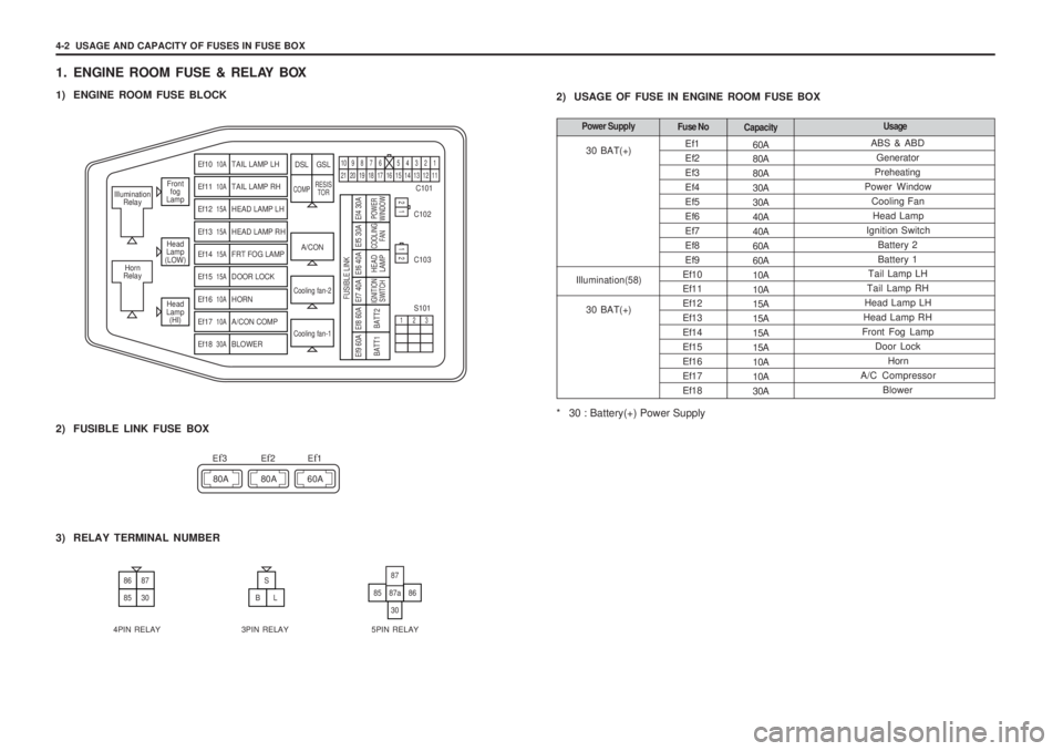
1. ENGINE ROOM FUSE & RELAY BOX
1) ENGINE ROOM FUSE BLOCK
2) USAGE OF FUSE IN ENGINE ROOM FUSE BOX
* 30 : Battery(+) Power Supply
Front
fog
Lamp
Head
Lamp
(LOW)
Head
Lamp (HI)
Illumination
Relay
Horn
Relay
A/CON C101
C102 C103 S101
Cooling fan-2
Cooling fan-1
Ef10 10ATAIL LAMP LH
Ef11 10ATAIL LAMP RH
Ef12 15AHEAD LAMP LH
Ef13 15AHEAD LAMP RH
Ef14 15AFRT FOG LAMP
Ef15 15ADOOR LOCK
Ef16 10AHORN
Ef17 10AA/CON COMP
Ef18 30ABLOWER
DSL GSL
COMP RESIS
TOR
109876 5432121 20 19 18 17 16 15 14 13 12 11
21
123
12
Ef9 60A
BATT1
Ef8 60ABATT2
Ef7 40AIGNITION SWITCH
Ef6 40A
FUSIBLE LINK
HEADLAMP
Ef5 30ACOOLING FAN
Ef4 30APOWER
WINDOW
2) FUSIBLE LINK FUSE BOX
80A 80A 60A
E
f3Ef2Ef1
3) RELAY TERMINAL NUMBER
8687
8530
S
BL8587a
30
87
86
4PIN RELAY 3PIN RELAY 5PIN RELAY ABS & ABD
Generator
Preheating
Power Window
Cooling FanHead Lamp
Ignition Switch Battery 2 Battery 1
Tail Lamp LH
Tail Lamp RH
Head Lamp LH
Head Lamp RH
Front Fog Lamp Door LockHorn
A/C Compressor
Blower
Fuse No Capacity UsagePower Supply
30 BAT(+)
Illumination(58)
30 BAT(+)
Page 1375 of 1574
5-8 ELECTRICAL WIRING DIAGRAMS
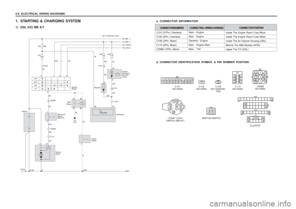
1. STARTING & CHARGING SYSTEM
1) GSL E23 MB A/TC101 (21Pin, Colorless) C102 (2Pin, Colorless) C108 (2Pin, Black) C110 (6Pin, Black) C208B (15Pin, Black)
b. CONNECTOR IDENTIFICATION SYMBOL & PIN NUMBER POSITION
a. CONNECTOR INFORMATION
C108
W/H GENERA- TOR C208B
W/H MAIN
C101
W/H MAIN C102
W/H MAIN C110
W/H MAIN
START LOCK
SWITCH (MB A/T) IGNITION SWITCH
CLUSTER
CONNECTOR(NUMBER)CONNECTING. WIRING HARNESS
Main - Engine Main - Engine Genertor - Engine Main - Engine MainMain - T/M
CONNECTOR POSITION
Inside The Engine Room Fuse Block Inside The Engine Room Fuse Block Under The Air Cleaner Housing (GSL)Behind The ABS Module (HFM) Upper The T/C (GSL)
12345 678910
11 12 13 14 15 16 17 18 19 20 211212
135 2 46
1
4 52
8
14
7
93
15
13
10
11 6
12
76
12
4
38 N
P IGNR
D
3910123 456
11 2
29 38
28
13 2021
39 434842
M
+-30 (BAT +)
: M/T (HFM E20, E23)
15 (IGN 1) 15A (IGN 2)
15C (ACC)
31 GND
Cluster (Charging
WarningLamp)
G105
G104
B B
G201
BST 3
4
OFF
"12"ICU
ACC
ONST BL
BY BY BY
BL
BG
BG 162
F22
10A
F24
10A
RG
W
RGLB 18 5
2 1 YW YW YW
C108
Generator
I.C Regulator D+
B+ 1
C101
Resister 15
C101
14
Ef7
40A
E
f2 80A
BW L LW
Ignition Switch
C102
1
Battery Start LockSwitch(MB A/T)
BY StarterMotor
1
30 87
8685
2
Clutch Switch
1 2
C110
4 C208B
PNP
Relay
8
C208B
2
Page 1377 of 1574
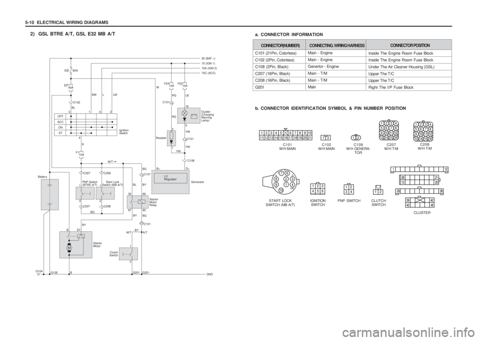
5-10 ELECTRICAL WIRING DIAGRAMSMain - Engine Main - Engine Genertor - Engine Main - T/MMain - T/M Main
2) GSL BTRE A/T, GSL E32 MB A/T
C101 (21Pin, Colorless) C102 (2Pin, Colorless) C108 (2Pin, Black) C207 (16Pin, Black) C208 (16Pin, Black) G201
b. CONNECTOR IDENTIFICATION SYMBOL & PIN NUMBER POSITION
a. CONNECTOR INFORMATION
C108
W/H GENERA- TOR C208
W/H T/M
C101
W/H MAIN C102
W/H MAIN C207
W/H T/M
START LOCK
SWITCH (MB A/T) IGNITION
SWITCH
CLUSTER
CONNECTOR(NUMBER)CONNECTING. WIRING HARNESSCONNECTOR POSITION
Inside The Engine Room Fuse Block Inside The Engine Room Fuse Block Under The Air Cleaner Housing (GSL)Upper The T/C Upper The T/C Right The I/P Fuse Block
12345 678910
11 12 13 14 15 16 17 18 19 20 211212
1234 5678
9 101112
13 14 15 16
76
12
4
38 N
P IGNR
D
3910123 456
11 2
29 38
28
13 2021
39 434842PNP SWITCH
12
34
CLUTCH SWITCH
12
M
30 (BAT +) 15 (IGN 1)15A (IGN 2)
15C (ACC)
31 GND
Cluster (Charging
WarningLamp)
G201
G201
G105 B BST3
4
OFF
ACC
ONST BL
R M/T
162
F22
10A
F24
10A
RG
W
RG
+-
LB 18 5
2 1 YW YW YW
C108
Generator
I.C Regulator D+
B+ 1
C101
Resister 15
C101
14
E f7
40A
F110A
E
f2 80A
BW L LW
Ignition Switch
C102
1
C207
Battery
PNP Switch(BTRE A/T) Start Lock
Switch (MB A/T)
BG BL BY
BY
BY BY
StarterMotor BG BG
1 3
12
12
4
C101
A/T
M/T 20C101
13
C208
3
C207
3 C208
4
87
Clutch
Switch 85
Starter Motor
Relay
30 86
G104
1234 5678
9 101112
13 14 15 16
Page 1379 of 1574
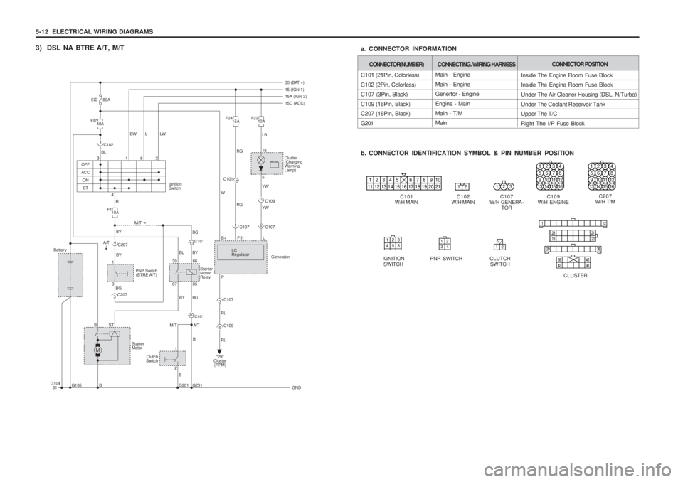
5-12 ELECTRICAL WIRING DIAGRAMS
3) DSL NA BTRE A/T, M/TMain - Engine Main - Engine Genertor - Engine Engine - MainMain - T/M Main
C101 (21Pin, Colorless) C102 (2Pin, Colorless) C107 (3Pin, Black) C109 (16Pin, Black) C207 (16Pin, Black) G201
b. CONNECTOR IDENTIFICATION SYMBOL & PIN NUMBER POSITION
a. CONNECTOR INFORMATION
C107
W/H GENERA- TOR C207
W/H T/M
C101
W/H MAIN C102
W/H MAIN C109
W/H ENGINE
IGNITION SWITCH
CLUSTER
CONNECTOR(NUMBER)CONNECTING. WIRING HARNESSCONNECTOR POSITION
Inside The Engine Room Fuse Block Inside The Engine Room Fuse Block Under The Air Cleaner Housing (DSL, N/Turbo)Under The Coolant Reservoir Tank Upper The T/C Right The I/P Fuse Block
12345 678910
11 12 13 14 15 16 17 18 19 20 2112123
1234 5678
9 101112
13 14 15 16
1234 5678
9 101112
13 14 15 16
123 456
11 2
29 38
28
13 2021
39 434842PNP SWITCH
12
34
CLUTCH
SWITCH
12
M
30 (BAT +) 15 (IGN 1)15A (IGN 2)
15C (ACC)
31 GND
Cluster (Charging
WarningLamp)
G201
G201
G105 B BST3
4
OFF
ACC
ONST BL
R M/T
A/T 162
F22
10A
F24
15A
RG RG
W
+-
LB 18 5 YW YW
C107
Generator
I.C Regulator L
B+ P 2
C109
10
C107
F(I)
1
C101
15
Ef7
40A
F110A
E
f2 80A
BW L LW
Ignition Switch
C102
1
C207
Battery
PNP Switch(BTRE A/T)
BG BL BY
BY
BY BY
B
B
Starter Motor
"29"
Cluster
(RPM)
BG BG
1 3
1 2
4
C101
A/T
M/T 20C101
13
C207
3 87
Clutch
Switch 85
Starter Motor
Relay
30 86
C107
RL RL
3
C109
9
G104