belt SSANGYONG MUSSO 2003 Service Manual
[x] Cancel search | Manufacturer: SSANGYONG, Model Year: 2003, Model line: MUSSO, Model: SSANGYONG MUSSO 2003Pages: 1574, PDF Size: 26.41 MB
Page 8 of 1574
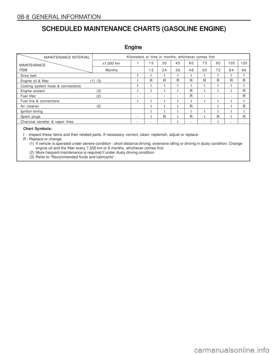
0B-8 GENERAL INFORMATIONSCHEDULED MAINTENANCE CHARTS (GASOLINE ENGINE)
Engine
Months
MAINTENANCE ITEM MAINTENANCE INTERVAL
Kilometers or time in months, whichever comes first
120
105
90
75
60
45
30
15
1
96
84
72
60
48
36
24
12
-
x1,000 km
Chart Symbols:
I - Inspect these items and their related parts. If necessary, correct, clean, replenish, adjust or replace. R - Replace or change.
(1) If vehicle is operated under severe condition : short distance driving, extensive idling or driving in dusty condition. Chan ge
engine oil and the filter every 7,500 km or 6 months, whichever comes first.
(2) More frequent maintenance is required if under dusty driving condition.
(3) Refer to “Recommended fluids and lubricants”.
Drive belt
Engine oil & filter (1) (3)Cooling system hose & connections
Engine coolant (3) Fuel filter
(2)
Fuel line & connections
Air cleaner (2)Ignition timingSpark plugsCharcoal canister & vapor lines
I III
- I
-- I
R II
- IIII
- I
R II
-
III
R - I
R II
- IIIII I
R I
RR I
R
I
R - I
R II
- I I I
- I
R II
- III
R I I
R II
- IIII
- I
R I
RR I
R I
R -
Page 9 of 1574
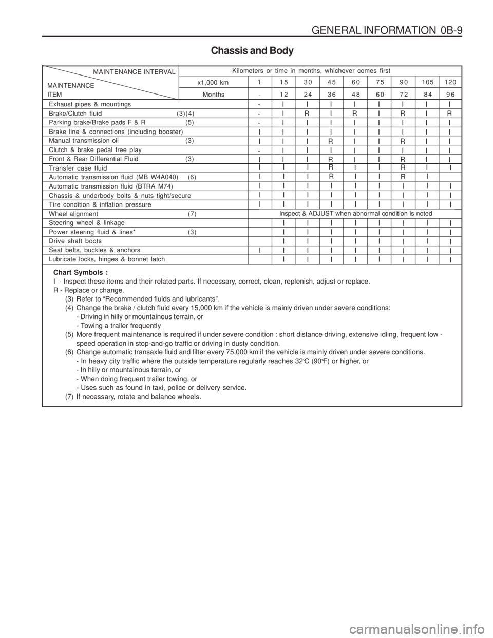
GENERAL INFORMATION 0B-9
Chassis and Body
Months
MAINTENANCE ITEM MAINTENANCE INTERVAL
Kilometers or time in months, whichever comes first
120
105
90
75
60
45
30
15
1
96
84
72
60
48
36
24
12
-
x1,000 km
Exhaust pipes & mountings Brake/Clutch fluid
(3)(4)
Parking brake/Brake pads F & R (5)Brake line & connections (including booster)
Manual transmission oil (3) Clutch & brake pedal free play
Front & Rear Differential Fluid (3)I
R
IIIII- --II
-
I IIIIII I
I
R I II I I IIII
R I
R IIIII I II
R
II
R I
R IIIIII II
R I IIII
Automatic transmission fluid (MB W4A040) (6) Automatic transmission fluid (BTRA M74)Chassis & underbody bolts & nuts tight/secure Tire condition & inflation pressure
Wheel alignment (7) Steering wheel & linkage
Power steering fluid & lines* (3)Drive shaft boots Seat belts, buckles & anchors Lubricate locks, hinges & bonnet latchIIII I I IIII I III I I IIII I IIII
R
III I IIII IIII I IIIIIIIII I III I
R R
III I IIII IIII I IIII
Transfer case fluidRII
I
Inspect & ADJUST when abnormal condition is noted
I
I II I IIII
Chart Symbols :
I - Inspect these items and their related parts. If necessary, correct, clean, replenish, adjust or replace.R - Replace or change.
(3) Refer to “Recommended fluids and lubricants”.
(4) Change the brake / clutch fluid every 15,000 km if the vehicle is mainly driven under severe conditions:- Driving in hilly or mountainous terrain, or
- Towing a trailer frequently
(5) More frequent maintenance is required if under severe condition : short distance driving, extensive idling, frequent low - speed operation in stop-and-go traffic or driving in dusty condition.
(6) Change automatic transaxle fluid and filter every 75,000 km if the vehicle is mainly driven under severe conditions. - In heavy city traffic where the outside temperature regularly reaches 32°C (90°F) or higher, or- In hilly or mountainous terrain, or- When doing frequent trailer towing, or- Uses such as found in taxi, police or delivery service.
(7) If necessary, rotate and balance wheels.
Page 10 of 1574
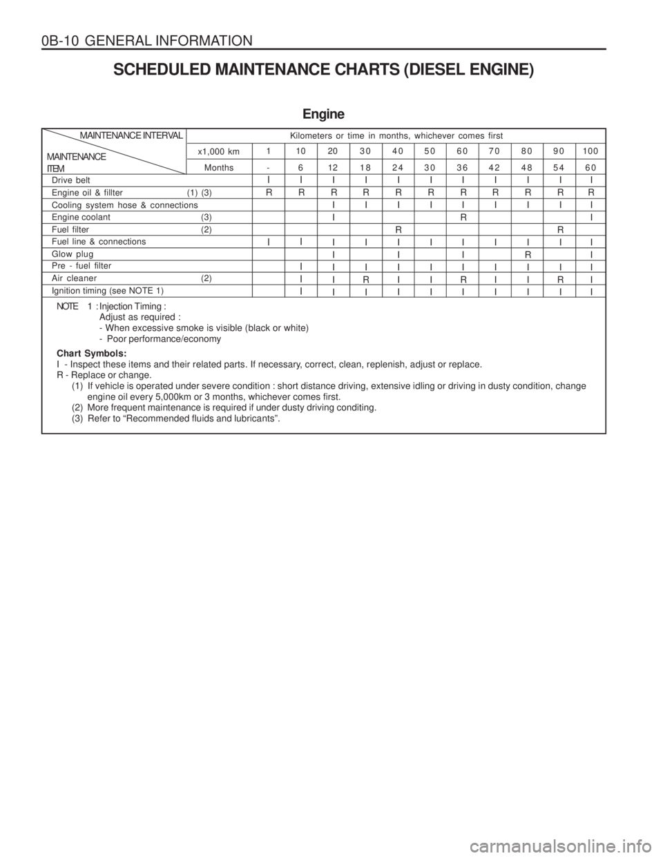
0B-10 GENERAL INFORMATIONSCHEDULED MAINTENANCE CHARTS (DIESEL ENGINE)
Engine
Months -
MAINTENANCE ITEM MAINTENANCE INTERVAL
Kilometers or time in months, whichever comes first
100
90
80
70
60
50
40
30
20
10
1
60
54
48
42
36
30
24
18
12
6
x1,000 km
NOTE 1 :
Injection Timing : Adjust as required :- When excessive smoke is visible (black or white)- Poor performance/economy
Chart Symbols:
I - Inspect these items and their related parts. If necessary, correct, clean, replenish, adjust or replace.R - Replace or change. (1) If vehicle is operated under severe condition : short distance driving, extensive idling or driving in dusty condition, chan ge
engine oil every 5,000km or 3 months, whichever comes first.
(2) More frequent maintenance is required if under dusty driving conditing.
(3) Refer to “Recommended fluids and lubricants”.
Drive belt Engine oil & fillter (1) (3)Cooling system hose & connections
Engine coolant (3)
Fuel filter (2) Fuel line & connections Glow plug Pre - fuel filter
Air cleaner (2)Ignition timing (see NOTE 1)
I
R
I
I
R
I I II
I
R I I I IIII I
R I I I
R I I
R I
R I IIII I
R I I I II I
R I
R
III
R I I
R I I I II I
R I I
R
I II I
R I
R I I
R I I
R I I I IIII
Page 11 of 1574
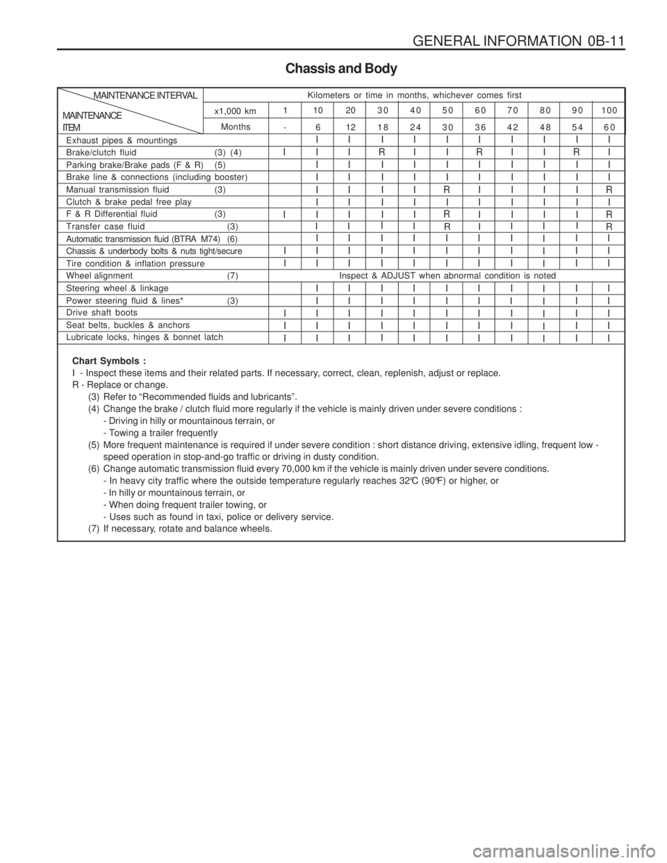
GENERAL INFORMATION 0B-11
Chassis and Body
Months -
MAINTENANCE ITEMMAINTENANCE INTERVAL
Kilometers or time in months, whichever comes first
100
90
80
70
60
50
40
30
20
10
1
60
54
48
42
36
30
24
18
12
6
x1,000 km
Exhaust pipes & mountings
Brake/clutch fluid (3) (4)
Parking brake/Brake pads (F & R) (5) Brake line & connections (including booster)
Manual transmission fluid (3)Clutch & brake pedal free play
F & R Differential fluid (3)
I I I IIIIIIIIIIIII I
R
IIIII IIIIIII IIII
R I
R I
R
IIIII IIIIIIIIIIIIII I
R
IIIII IIII
R I
R
Automatic transmission fluid (BTRA M74) (6) Chassis & underbody bolts & nuts tight/secure Tire condition & inflation pressure
Wheel alignment (7) Steering wheel & linkage
Power steering fluid & lines* (3) Drive shaft boots Seat belts, buckles & anchors Lubricate locks, hinges & bonnet latchI II I IIII III I IIII IIII I III I
I II I IIII III I IIIIIII I IIII III II II III I IIIIIII I IIII
Transfer case fluid (3)
RI R
I
I
I
I I I II IIII I IIII
Inspect & ADJUST when abnormal condition is noted
II I
Chart Symbols :
I - Inspect these items and their related parts. If necessary, correct, clean, replenish, adjust or replace.R - Replace or change.
(3) Refer to “Recommended fluids and lubricants”.
(4) Change the brake / clutch fluid more regularly if the vehicle is mainly driven under severe conditions :- Driving in hilly or mountainous terrain, or
- Towing a trailer frequently
(5) More frequent maintenance is required if under severe condition : short distance driving, extensive idling, frequent low - speed operation in stop-and-go traffic or driving in dusty condition.
(6) Change automatic transmission fluid every 70,000 km if the vehicle is mainly driven under severe conditions. - In heavy city traffic where the outside temperature regularly reaches 32°C (90°F) or higher, or- In hilly or mountainous terrain, or- When doing frequent trailer towing, or- Uses such as found in taxi, police or delivery service.
(7) If necessary, rotate and balance wheels.
Page 13 of 1574
GENERAL INFORMATION 0B-13
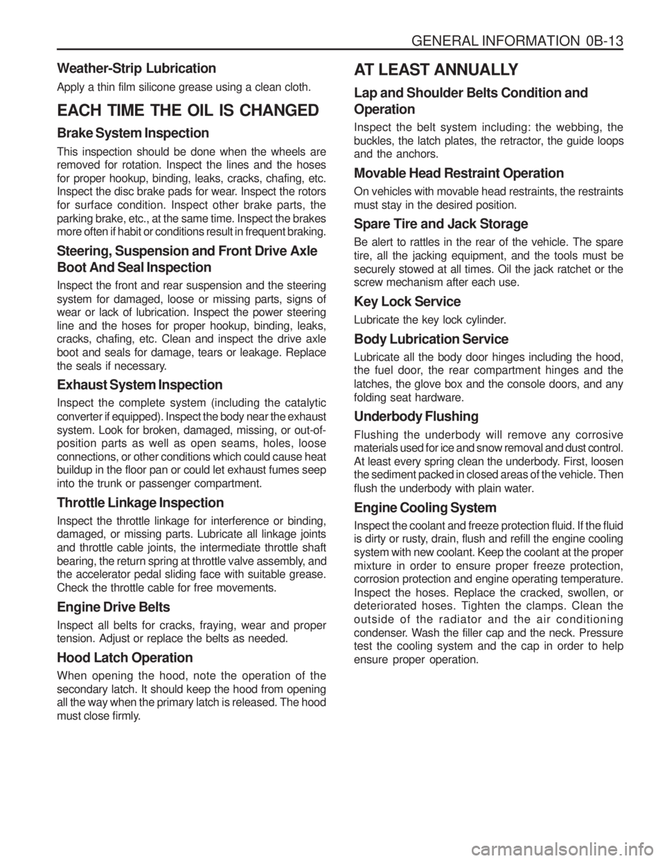
Weather-Strip Lubrication Apply a thin film silicone grease using a clean cloth. EACH TIME THE OIL IS CHANGED Brake System Inspection This inspection should be done when the wheels are removed for rotation. Inspect the lines and the hoses for proper hookup, binding, leaks, cracks, chafing, etc.
Inspect the disc brake pads for wear. Inspect the rotors for surface condition. Inspect other brake parts, theparking brake, etc., at the same time. Inspect the brakes more often if habit or conditions result in frequent braking. Steering, Suspension and Front Drive Axle Boot And Seal Inspection Inspect the front and rear suspension and the steering system for damaged, loose or missing parts, signs of wear or lack of lubrication. Inspect the power steering line and the hoses for proper hookup, binding, leaks, cracks, chafing, etc. Clean and inspect the drive axle boot and seals for damage, tears or leakage. Replace
the seals if necessary. Exhaust System Inspection Inspect the complete system (including the catalytic converter if equipped). Inspect the body near the exhaustsystem. Look for broken, damaged, missing, or out-of- position parts as well as open seams, holes, loose connections, or other conditions which could cause heat buildup in the floor pan or could let exhaust fumes seep into the trunk or passenger compartment. Throttle Linkage Inspection Inspect the throttle linkage for interference or binding, damaged, or missing parts. Lubricate all linkage joints and throttle cable joints, the intermediate throttle shaft
bearing, the return spring at throttle valve assembly, and the accelerator pedal sliding face with suitable grease. Check the throttle cable for free movements. Engine Drive Belts Inspect all belts for cracks, fraying, wear and proper tension. Adjust or replace the belts as needed. Hood Latch Operation When opening the hood, note the operation of the secondary latch. It should keep the hood from opening all the way when the primary latch is released. The hood
must close firmly. AT LEAST ANNUALLY Lap and Shoulder Belts Condition and Operation Inspect the belt system including: the webbing, the
buckles, the latch plates, the retractor, the guide loops and the anchors. Movable Head Restraint Operation On vehicles with movable head restraints, the restraints must stay in the desired position. Spare Tire and Jack Storage Be alert to rattles in the rear of the vehicle. The spare tire, all the jacking equipment, and the tools must besecurely stowed at all times. Oil the jack ratchet or the screw mechanism after each use. Key Lock Service
Lubricate the key lock cylinder. Body Lubrication Service Lubricate all the body door hinges including the hood,
the fuel door, the rear compartment hinges and the latches, the glove box and the console doors, and anyfolding seat hardware. Underbody Flushing Flushing the underbody will remove any corrosive materials used for ice and snow removal and dust control.
At least every spring clean the underbody. First, loosen the sediment packed in closed areas of the vehicle. Then
flush the underbody with plain water. Engine Cooling System Inspect the coolant and freeze protection fluid. If the fluid
is dirty or rusty, drain, flush and refill the engine cooling system with new coolant. Keep the coolant at the propermixture in order to ensure proper freeze protection, corrosion protection and engine operating temperature. Inspect the hoses. Replace the cracked, swollen, or
deteriorated hoses. Tighten the clamps. Clean the outside of the radiator and the air conditioning
condenser. Wash the filler cap and the neck. Pressure test the cooling system and the cap in order to help ensure proper operation.
Page 16 of 1574
0B-16 GENERAL INFORMATIONVEHICLE IDENTIFICATION NUMBER SYSTEM
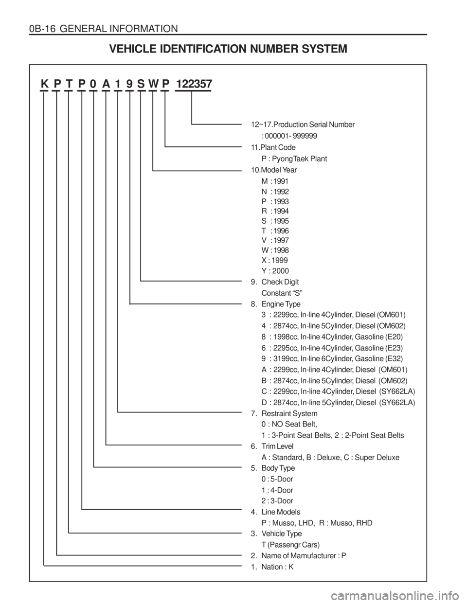
K P T P 0 A 1 9 S W P 122357
12~17.Production Serial Number: 000001- 999999
11.Plant Code P : PyongTaek Plant
10.Model Year
M : 1991
N : 1992
P : 1993
R : 1994
S : 1995
T : 1996
V : 1997
W : 1998X : 1999 Y : 2000
9. Check Digit Constant “S”
8. Engine Type 3 : 2299cc, In-line 4Cylinder, Diesel (OM601)
4 : 2874cc, In-line 5Cylinder, Diesel (OM602)
8 : 1998cc, In-line 4Cylinder, Gasoline (E20)
6 : 2295cc, In-line 4Cylinder, Gasoline (E23)
9 : 3199cc, In-line 6Cylinder, Gasoline (E32)
A : 2299cc, In-line 4Cylinder, Diesel (OM601)
B : 2874cc, In-line 5Cylinder, Diesel (OM602)
C : 2299cc, In-line 4Cylinder, Diesel (SY662LA)
D : 2874cc, In-line 5Cylinder, Diesel (SY662LA)
7. Restraint System 0 : NO Seat Belt,1 : 3-Point Seat Belts, 2 : 2-Point Seat Belts
6 . Trim Level A : Standard, B : Deluxe, C : Super Deluxe
5. Body Type
0 : 5-Door1 : 4-Door 2 : 3-Door
4. Line Models P : Musso, LHD, R : Musso, RHD
3. Vehicle Type
T (Passengr Cars)
2. Name of Mamufacturer : P
1. Nation : K
Page 37 of 1574
SECTION 1B1
M162 ENGINE MECHANICAL
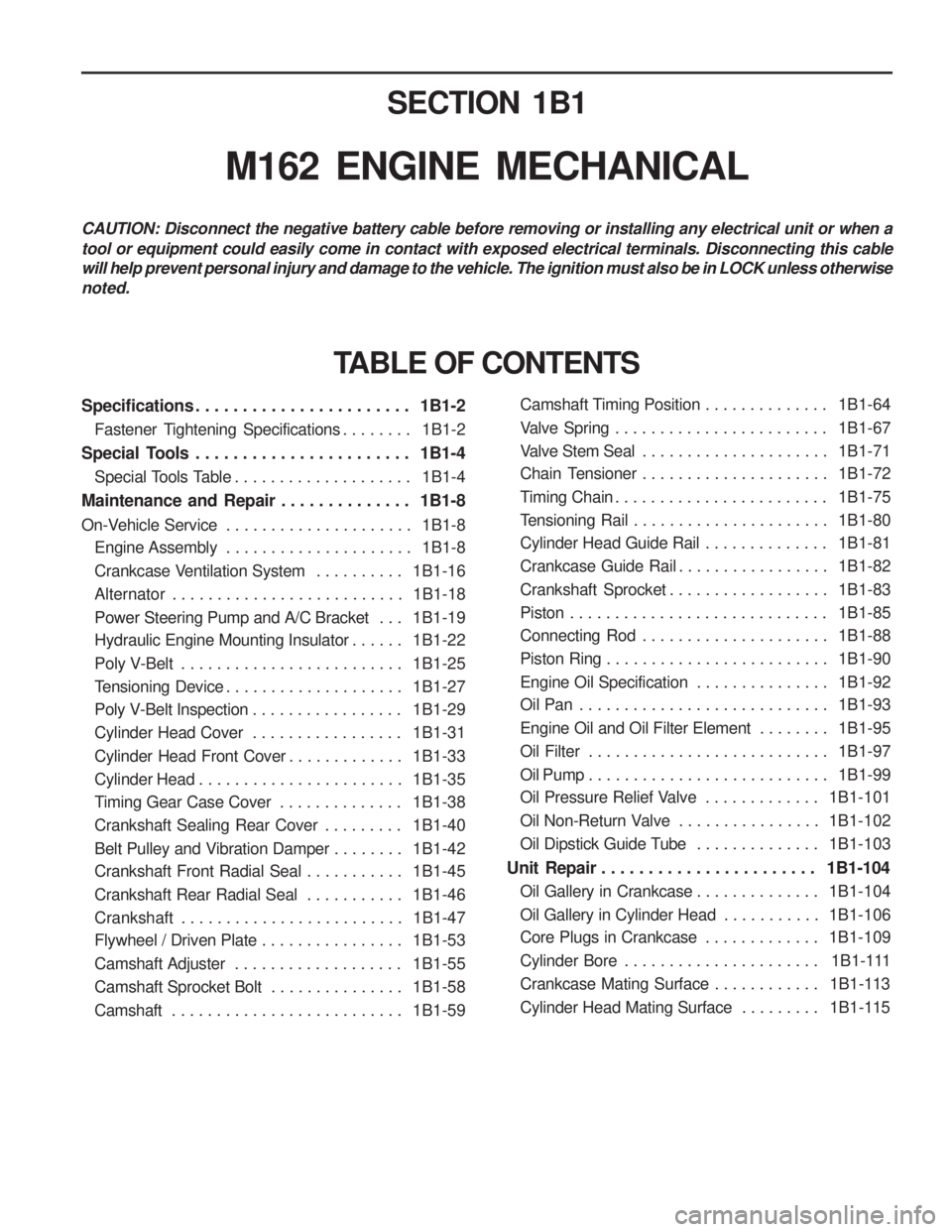
CAUTION: Disconnect the negative battery cable before removing or installing any electrical unit or when a tool or equipment could easily come in contact with exposed electrical terminals. Disconnecting this cable will help prevent personal injury and damage to the vehicle. The ignition must also be in LOCK unless otherwisenoted.
Specifications . . . . . . . . . . . . . . . . . . . . . . . 1B1-2Fastener Tightening Specifications . . . . . . . . 1B1-2
Special Tools . . . . . . . . . . . . . . . . . . . . . . . 1B1-4 Special Tools Table . . . . . . . . . . . . . . . . . . . . 1B1-4
Maintenance and Repair . . . . . . . . . . . . . . 1B1-8
On-Vehicle Service . . . . . . . . . . . . . . . . . . . . . 1B1-8
Engine Assembly . . . . . . . . . . . . . . . . . . . . . 1B1-8
Crankcase Ventilation System . . . . . . . . . . 1B1-16
Alternator . . . . . . . . . . . . . . . . . . . . . . . . . . 1B1-18
Power Steering Pump and A/C Bracket . . . 1B1-19
Hydraulic Engine Mounting Insulator . . . . . . 1B1-22
Poly V-Belt . . . . . . . . . . . . . . . . . . . . . . . . . 1B1-25
Tensioning Device . . . . . . . . . . . . . . . . . . . . 1B1-27
Poly V-Belt Inspection . . . . . . . . . . . . . . . . . 1B1-29
Cylinder Head Cover . . . . . . . . . . . . . . . . . 1B1-31
Cylinder Head Front Cover . . . . . . . . . . . . . 1B1-33
Cylinder Head . . . . . . . . . . . . . . . . . . . . . . . 1B1-35
Timing Gear Case Cover . . . . . . . . . . . . . . 1B1-38
Crankshaft Sealing Rear Cover . . . . . . . . . 1B1-40
Belt Pulley and Vibration Damper . . . . . . . . 1B1-42
Crankshaft Front Radial Seal . . . . . . . . . . . 1B1-45
Crankshaft Rear Radial Seal . . . . . . . . . . . 1B1-46
Crankshaft . . . . . . . . . . . . . . . . . . . . . . . . . 1B1-47
Flywheel / Driven Plate . . . . . . . . . . . . . . . . 1B1-53
Camshaft Adjuster . . . . . . . . . . . . . . . . . . . 1B1-55
Camshaft Sprocket Bolt . . . . . . . . . . . . . . . 1B1-58
Camshaft . . . . . . . . . . . . . . . . . . . . . . . . . . 1B1-59
TABLE OF CONTENTS
Camshaft Timing Position . . . . . . . . . . . . . . 1B1-64
Valve Spring . . . . . . . . . . . . . . . . . . . . . . . . 1B1-67
Valve Stem Seal . . . . . . . . . . . . . . . . . . . . . 1B1-71
Chain Tensioner . . . . . . . . . . . . . . . . . . . . . 1B1-72
Timing Chain . . . . . . . . . . . . . . . . . . . . . . . . 1B1-75
Tensioning Rail . . . . . . . . . . . . . . . . . . . . . . 1B1-80
Cylinder Head Guide Rail . . . . . . . . . . . . . . 1B1-81
Crankcase Guide Rail . . . . . . . . . . . . . . . . . 1B1-82
Crankshaft Sprocket . . . . . . . . . . . . . . . . . . 1B1-83
Piston . . . . . . . . . . . . . . . . . . . . . . . . . . . . . 1B1-85
Connecting Rod . . . . . . . . . . . . . . . . . . . . . 1B1-88
Piston Ring . . . . . . . . . . . . . . . . . . . . . . . . . 1B1-90
Engine Oil Specification . . . . . . . . . . . . . . . 1B1-92
Oil Pan . . . . . . . . . . . . . . . . . . . . . . . . . . . . 1B1-93
Engine Oil and Oil Filter Element . . . . . . . . 1B1-95
Oil Filter . . . . . . . . . . . . . . . . . . . . . . . . . . . 1B1-97
Oil Pump . . . . . . . . . . . . . . . . . . . . . . . . . . . 1B1-99
Oil Pressure Relief Valve . . . . . . . . . . . . . 1B1-101
Oil Non-Return Valve . . . . . . . . . . . . . . . . 1B1-102
Oil Dipstick Guide Tube . . . . . . . . . . . . . . 1B1-103
Unit Repair . . . . . . . . . . . . . . . . . . . . . . . 1B1-104 Oil Gallery in Crankcase . . . . . . . . . . . . . . 1B1-104
Oil Gallery in Cylinder Head . . . . . . . . . . . 1B1-106
Core Plugs in Crankcase . . . . . . . . . . . . . 1B1-109
Cylinder Bore . . . . . . . . . . . . . . . . . . . . . . 1B1-111
Crankcase Mating Surface . . . . . . . . . . . . 1B1-113
Cylinder Head Mating Surface . . . . . . . . . 1B1-115
Page 38 of 1574
1B1-2 M162 ENGINE MECHANICALSPECIFICATIONS
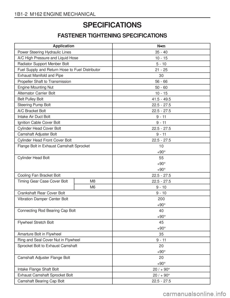
FASTENER TIGHTENING SPECIFICATIONS N
m
35 - 40 10 - 15 5 - 10
21 - 25 30
56 - 6650 - 60 10 - 15
41.5 - 49.522.5 - 27.522.5 - 27.5
9 - 11
9 - 11
22.5 - 27.5
9 - 11
22.5 - 27.5
10
+90 °
55
+90 °
+90 °
22.5 - 27.522.5 - 27.5 9 - 109 - 10200
+90 °
40
+90 °
45
+90 °
35
9 - 11 20
+90 °
20
+90 °
20 / + 90 °
20 / + 90 °
22.5 - 27.5
Application
Power Steering Hydraulic Lines A/C High Pressure and Liquid HoseRadiator Support Menber BoltFuel Supply and Return Hose to Fuel DistributorExhaust Manifold and Pipe
Propeller Shaft to Transmission Engine Mounting NutAlternator Carrier BoltBelt Pulley BoltSteering Pump Bolt A/C Bracket Bolt Intake Air Duct BoltIgnition Cable Cover BoltCylinder Head Cover BoltCamshaft Adjuster Bolt Cylinder Head Front Cover Bolt Flange Bolt in Exhaust Camshaft Sprocket Cylinder Head Bolt Cooling Fan Bracket Bolt
Timing Gear Case Cover Bolt M8 M6
Crankshaft Rear Cover BoltVibration Damper Center Bolt Connecting Rod Bearing Cap Bolt Flywheel Stretch Bolt Amarture Bolt in Flywheel Ring and Seal Cover Nut in FlywheelSprocket Bolt to Exhaust Camshaft Camshaft Adjuster Flange Bolt Intake Flange Shaft Bolt Exhaust Camshaft Sprocket Bolt Camshaft Bearing Cap Bolt
Page 54 of 1574

1B1-18 M162 ENGINE MECHANICAL
ALTERNATOR
1 Nut (M8)......................................... 22.5-27.5 Nm
2 Bolt (M8 x 30, 3 pieces) .................22.5-27.5 Nm
3 Bolt (M8 x 40, 1 piece) ...................22.5-27.5 Nm
Removal & Installation Procedure
1. Remove the drive belt.
2. Remove the alternator.
3. Unscrew the alternator carrier bolts and remove the carrier. Installation Notice 4 Bolt (M8 x 70, 1 piece)
...................22.5-27.5 Nm
5 Bolt (M8 x 75, 1 piece) ...................22.5-27.5 Nm
Tightening Torque 10 - 15 Nm
4. Installation should follow the removal procedure in the reverse order.
Page 56 of 1574

1B1-20 M162 ENGINE MECHANICAL Removal & Installation Procedure
1. Remove the belt pulley.Installation Notice
2. Disconnect the hydraulic pipe of the power steering pump and drain the oil.
3. Unscrew the bolts (arrows) and remove the steering pump. Installation Notice
Notice Pull the tensioning pulley clockwise as shown in the figure.
4. Remove the compressor after disconnecting the wiring connector and refrigerant pipe of A/C compressor. Notice Discharge all the refrigerant before removing the pipes.
Tightening Torque 40.5 - 49.5 Nm
Tightening Torque 22.5 - 27.5 Nm