turn signal SSANGYONG MUSSO 2003 User Guide
[x] Cancel search | Manufacturer: SSANGYONG, Model Year: 2003, Model line: MUSSO, Model: SSANGYONG MUSSO 2003Pages: 1574, PDF Size: 26.41 MB
Page 1096 of 1574
TRANSFER CASE (TOD) 5D2-7
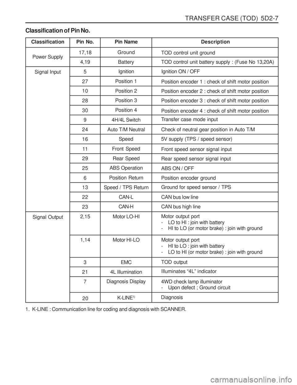
1. K-LINE : Communication line for coding and diagnosis with SCANNER.
Classification of Pin No.
Classification
Pin No. Pin Name Description
Power Supply 17,18
Ground
TOD control unit ground
4,19 Battery TOD control unit battery supply : (Fuse No 13,20A)
5 Ignition Ignition ON / OFF
27 Position 1
Position encoder 1 : check of shift motor position
10 Position 2 Position encoder 2 : check of shift motor position
28 Position 3
Position encoder 3 : check of shift motor position
30 Position 4
Position encoder 4 : check of shift motor position
9 4H/4L Switch Transfer case mode input
24 Auto T/M Neutral Check of neutral gear position in Auto T/M 16 Speed 5V supply (TPS / speed sensor)
11 Front Speed
Front speed sensor signal input
Signal Input
29 Rear Speed Rear speed sensor signal input
25 ABS Operation
ABS ON / OFF
6 Position Return
Position encoder ground
13 Speed / TPS Return Ground for speed sensor / TPS
2 2 CAN-L CAN bus low line
23 CAN-H
CAN bus high line
2,15 Motor LO-HI Motor output port
- LO to HI : join with battery
- HI to LO (or motor brake) : join with ground
1,14 Motor HI-LO Motor output port
- HI to LO : join with battery
- LO to HI (or motor brake) : join with ground
3 EMC TOD output
Signal Output
21 4L Illumination Illuminates
“4L ” indicator
7 Diagnosis Display
4WD check lamp illuminator
- Upon defect ; Ground circuit
20K-LINE1)
Diagnosis
Page 1100 of 1574
TRANSFER CASE (TOD) 5D2-11
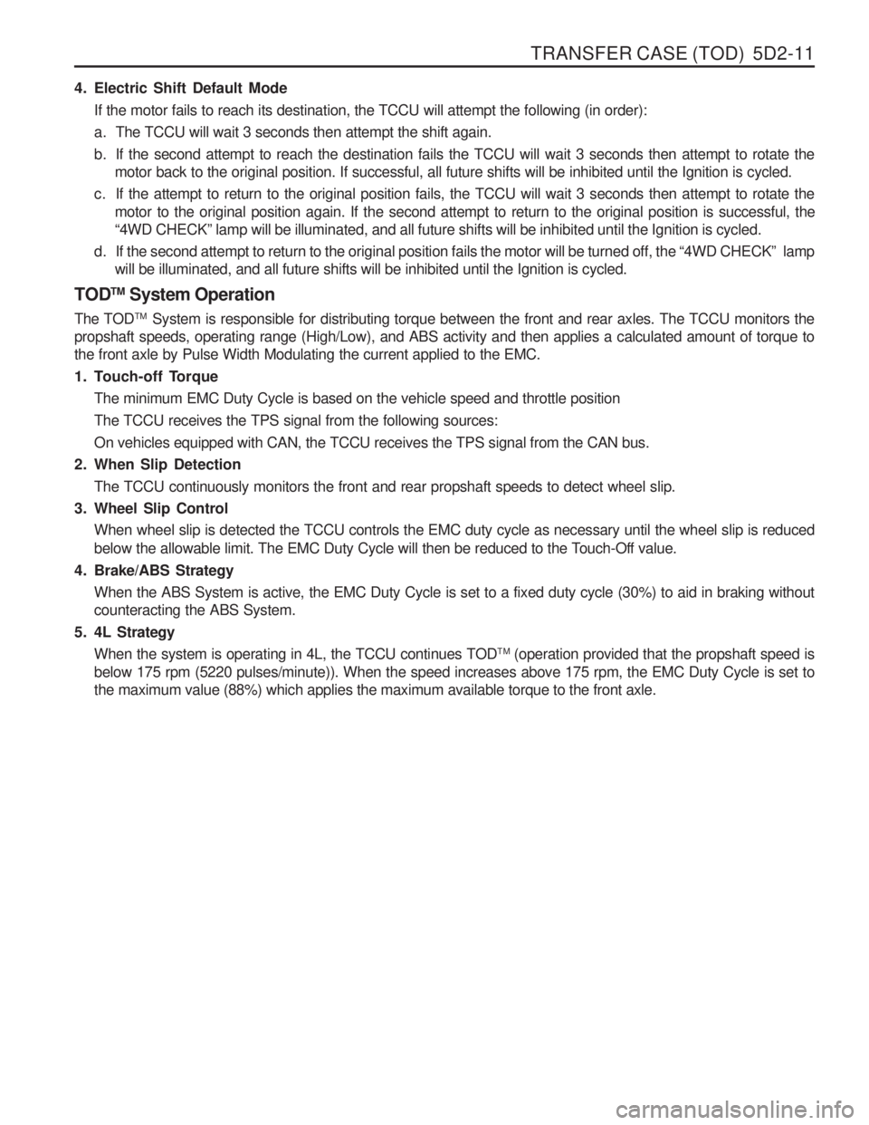
4. Electric Shift Default ModeIf the motor fails to reach its destination, the TCCU will attempt the following (in order):
a. The TCCU will wait 3 seconds then attempt the shift again.
b. If the second attempt to reach the destination fails the TCCU will wait 3 seconds then attempt to rotate the motor back to the original position. If successful, all future shifts will be inhibited until the Ignition is cycled.
c. If the attempt to return to the original position fails, the TCCU will wait 3 seconds then attempt to rotate the motor to the original position again. If the second attempt to return to the original position is successful, the “4WD CHECK ” lamp will be illuminated, and all future shifts will be inhibited until the Ignition is cycled.
d. If the second attempt to return to the original position fails the motor will be turned off, the “4WD CHECK ” lamp
will be illuminated, and all future shifts will be inhibited until the Ignition is cycled.
TOD TM
System Operation
The TOD TM
System is responsible for distributing torque between the front and rear axles. The TCCU monitors the
propshaft speeds, operating range (High/Low), and ABS activity and then applies a calculated amount of torque tothe front axle by Pulse Width Modulating the current applied to the EMC.
1. Touch-off Torque
The minimum EMC Duty Cycle is based on the vehicle speed and throttle positionThe TCCU receives the TPS signal from the following sources:On vehicles equipped with CAN, the TCCU receives the TPS signal from the CAN bus.
2. When Slip Detection
The TCCU continuously monitors the front and rear propshaft speeds to detect wheel slip.
3. Wheel Slip Control When wheel slip is detected the TCCU controls the EMC duty cycle as necessary until the wheel slip is reduced
below the allowable limit. The EMC Duty Cycle will then be reduced to the Touch-Off value.
4. Brake/ABS Strategy When the ABS System is active, the EMC Duty Cycle is set to a fixed duty cycle (30%) to aid in braking without counteracting the ABS System.
5. 4L Strategy When the system is operating in 4L, the TCCU continues TOD TM
(operation provided that the propshaft speed is
below 175 rpm (5220 pulses/minute)). When the speed increases above 175 rpm, the EMC Duty Cycle is set tothe maximum value (88%) which applies the maximum available torque to the front axle.
Page 1188 of 1574

8B-8 SUPPLEMENTAL RESTRAINT SYSTEM(SRS) Energy Reserve System Energy reserve system is consisted of condensor and energy switch and will check following items continuously during system operation.
- High voltage
- Low voltage
- Low rating capacity
- Function of the energy reserve switchIf there is fault in the energy reserve system, warning lamp will turn on. And defects are found by continuouschecking of the condenser voltage, the system will enter overall shutdown status for safety reason. Shutdown Switch There is 1 energy shutdown switch in the system and it will be checked during start-up. And it also checks that
condenser is discharging properly. If shutdown switch is short, it will be detected during condensor voltage test. If squib line fault is obvious, the warning lamp will turn on and the module will enter overall shutdown status. Accelerometer Check Accelerometer function will be checked during start-up. During operation, accelerometer off-set signal will be checked, If there is fault, module will enter overall shutdown status. ASIC Overheat
Module monitors upper side ASIC overheats continuously. If overheated, the module will enter overall shutdown status. Microprocessor Fault Module checks EEPROM, ROM checksum and RAM during start-up. EEPROM tests checksum operation.If RAM or ROM checksum is defective, module will not allow start-up continuously but will be re-set,If EEPROM is defective, warning lamp will turn on and the module will enter overall shutdown status.During operation, RAM will continuously verify the proper operation of temporary memory program data usage. If there is fault, the module will enter overall shutdown status and the warning lamp will turn on.
Watchdog Test
Watchdog function will be tested in start-up. If there is fault during the test, warning lamp will turn on and the module will enter overall shutdown status.
Page 1208 of 1574

9A-6 BODY WIRING SYSTEM Engine Room Fuse (EF) and Relay Box1 Fuse (15A) : ABS, ABD
2 Fuse (20A) : Sun Roof
3 Fuse (10A) : Air Bag
4 Fuse (15A) : Audio, Clock, Out Side Mirror
5 Fuse (30A) : Cigarette lighter, Power Socket
6 Fuse (30A) : Heater
7 Fuse (15A) : Door Lock
8 Fuse (30A) : Rear Heated
9 Fuse (10A) : Audio, Buzzer, Chime, Clock
10 Fuse (30A) : Power Window
11 Fuse (10A) : Immobilizer
12 Fuse (20A) : T/C
13 Fuse (15A) : Interior Lamp
14 Fuse (15A) : Hazard Lamp
15 Fuse (15A) : Stop Lamp
16 Fuse (15A) : Turn signal Lamp, Head Lamp
17 Fuse (10A) : Back up Lamp
18 Fuse (15A) : Cluster, STICS
19 Fuse (15A) : A/T, Diagnosis
20 Fuse (15A) : Over Voltage Protection Relay (Gasolin Only)
21 Fuse (15A) : Seat Heater
22 Fuse (15A) : ECS
23 Fuse (15A) : Front Wiper & Washer
24 Fuse (10A) : Rear Wiper & Washer, A/C
25 Relay : Front Wiper 26 Relay : ABS Warning Lamp
27 Relay : Flasher Unit
28 Relay : Fuel Pump (Gasoline Only)
29 Relay : Shift Lock (A/T)
30 Relay : Clutch Interlock & Neutral
31 Relay : Sun Roof
32 Relay : A/T ‘B’ Interlock (MB A/T)
33 Relay : Power Window
34 Relay : Rear Fog Lamp
35 Relay : ECS
36 Relay : Compressor (Diesel E/G)
Condenser Fan (Gasoline E/G)
37 Relay : Condenser Fan
38 Relay : Air Conditioner
39 Fuse (10A) : Tail Lamp
40 Fuse (15A) : Head Lamp(LH)
41 Fuse (15A) : Head Lamp(RH)
42 Fuse (15A) : Front Fog Lamp
43 Fuse (10A) : Horn
44 Fuse (10A) : Compressor
45 Relay : Resistor with Diode (Gasoline E/G)
46 Relay : Front fog Lamp
47 Relay : Condenser Fan
48 Relay : Tail Lamp
49 Relay : Horn
Page 1229 of 1574
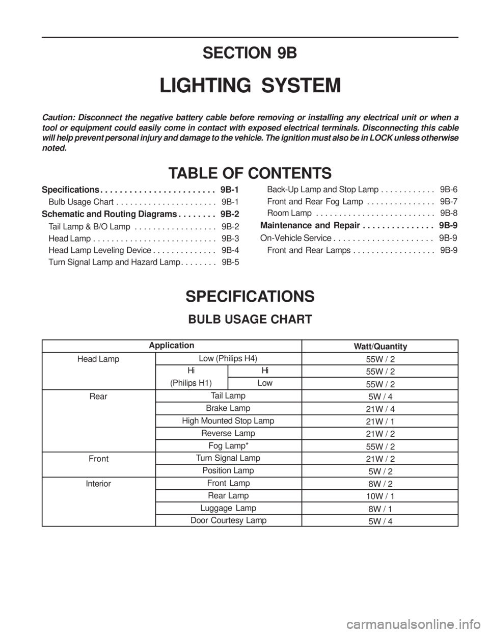
Low (Philips H4)Tail Lamp
Brake Lamp
High Mounted Stop Lamp Reverse LampFog Lamp*
Turn Signal Lamp Position Lamp
Front LampRear Lamp
Luggage Lamp
Door Courtesy Lamp SECTION 9B
LIGHTING SYSTEM
Caution: Disconnect the negative battery cable before removing or installing any electrical unit or when a tool or equipment could easily come in contact with exposed electrical terminals. Disconnecting this cable will help prevent personal injury and damage to the vehicle. The ignition must also be in LOCK unless otherwisenoted.
TABLE OF CONTENTS
SPECIFICATIONSBULB USAGE CHART
Head Lamp Rear
Front
Interior
Application
Specifications . . . . . . . . . . . . . . . . . . . . . . . . 9B-1
Bulb Usage Chart . . . . . . . . . . . . . . . . . . . . . . 9B-1
Schematic and Routing Diagrams . . . . . . . . 9B-2 Tail Lamp & B/O Lamp . . . . . . . . . . . . . . . . . . 9B-2
Head Lamp . . . . . . . . . . . . . . . . . . . . . . . . . . . 9B-3
Head Lamp Leveling Device . . . . . . . . . . . . . . 9B-4
Turn Signal Lamp and Hazard Lamp . . . . . . . . 9B-5 Back-Up Lamp and Stop Lamp . . . . . . . . . . . .
9B-6
Front and Rear Fog Lamp . . . . . . . . . . . . . . . 9B-7
Room Lamp . . . . . . . . . . . . . . . . . . . . . . . . . . 9B-8
Maintenance and Repair . . . . . . . . . . . . . . . 9B-9
On-Vehicle Service . . . . . . . . . . . . . . . . . . . . . 9B-9 Front and Rear Lamps . . . . . . . . . . . . . . . . . . 9B-9
Hi
(Philips H1)
Hi
Low Watt/Quantity
55W / 2 55W / 2 55W / 25W / 4
21W / 4 21W / 121W / 2 55W / 2 21W / 2 5W / 28W / 2
10W / 1
8W / 15W / 4
Page 1233 of 1574
LIGHTING SYSTEM 9B-5
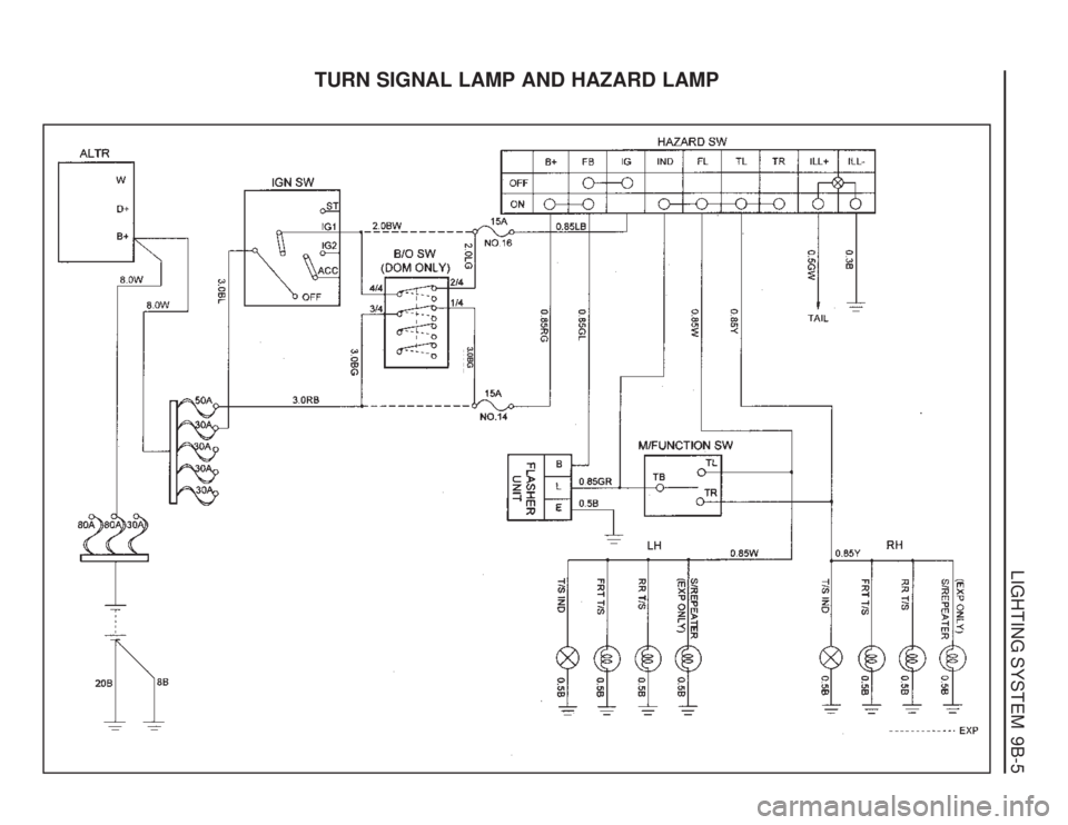
TURN SIGNAL LAMP AND HAZARD LAMP
3.0BG
Page 1237 of 1574

LIGHTING SYSTEM 9B-9
FRONT AND REAR LAMPS
1 Low-beam Head Lamp
2 High-beam Head Lamp
3 Turn Signal Lamp
4 Position Lamp5 Back-up Lamp
6 Tail / Stop Lamp
7 Turn Signal Lamp
8 Tail / Stop Lamp
MAINTENANCE AND REPAIR
ON-VEHICLE SERVICE
Page 1240 of 1574
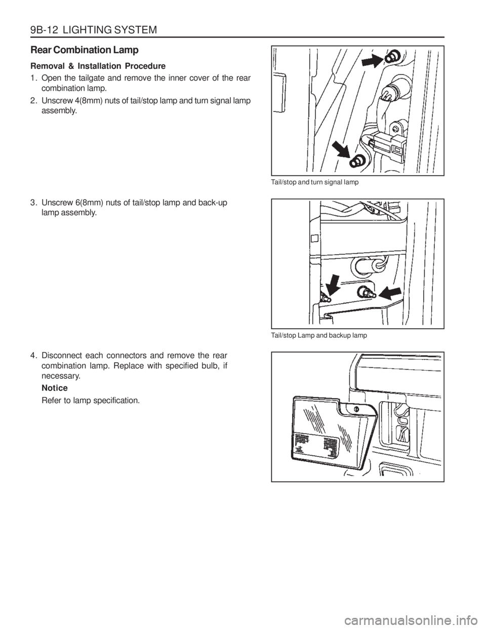
9B-12 LIGHTING SYSTEM
Tail/stop and turn signal lamp
Tail/stop Lamp and backup lamp
Rear Combination Lamp Removal & Installation Procedure
1. Open the tailgate and remove the inner cover of the rear
combination lamp.
2. Unscrew 4(8mm) nuts of tail/stop lamp and turn signal lamp assembly.
3. Unscrew 6(8mm) nuts of tail/stop lamp and back-up lamp assembly.
4. Disconnect each connectors and remove the rear combination lamp. Replace with specified bulb, if
necessary. NoticeRefer to lamp specification.
Page 1252 of 1574
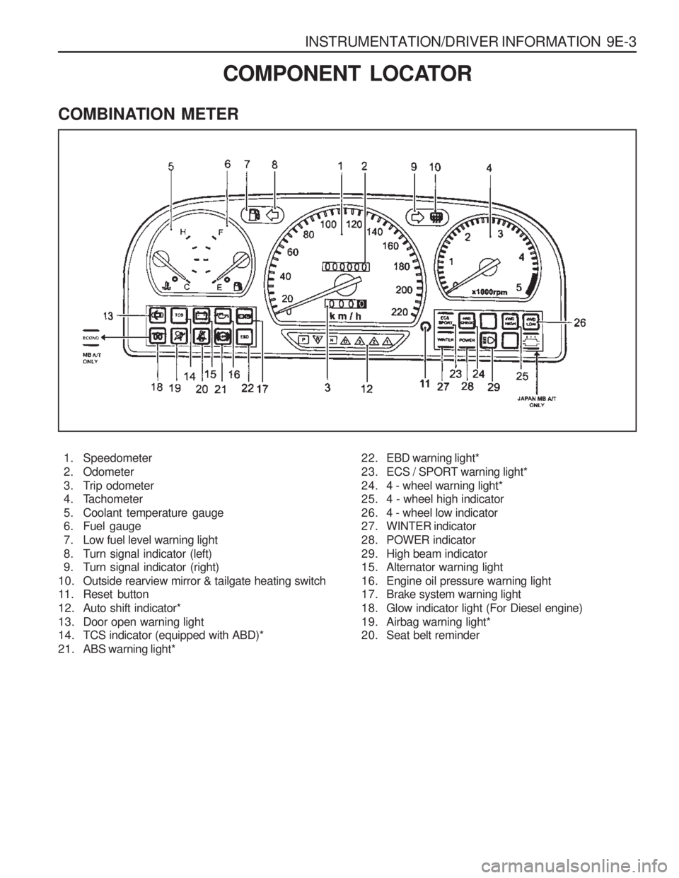
INSTRUMENTATION/DRIVER INFORMATION 9E-3
COMBINATION METER
COMPONENT LOCATOR
1. Speedometer
2. Odometer
3. Trip odometer
4. Tachometer
5. Coolant temperature gauge
6. Fuel gauge
7. Low fuel level warning light
8. Turn signal indicator (left)
9. Turn signal indicator (right)
10. Outside rearview mirror & tailgate heating switch
11. Reset button
12. Auto shift indicator*
13. Door open warning light
14. TCS indicator (equipped with ABD)*
21. ABS warning light* 22. EBD warning light*
23. ECS / SPORT warning light*
24. 4 - wheel warning light*
25. 4 - wheel high indicator
26. 4 - wheel low indicator
27. WINTER indicator
28. POWER indicator
29. High beam indicator
15. Alternator warning light
16. Engine oil pressure warning light
17. Brake system warning light
18. Glow indicator light (For Diesel engine)
19. Airbag warning light*
20. Seat belt reminder
Page 1309 of 1574
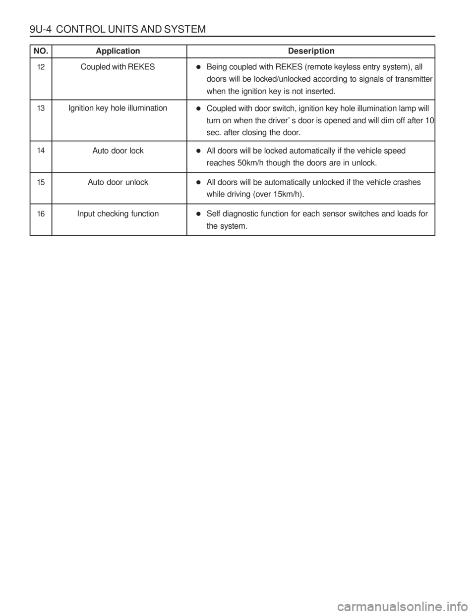
9U-4 CONTROL UNITS AND SYSTEM
NO. ApplicationDeseription
13 Ignition key hole illumination
�Coupled with door switch, ignition key hole illumination lamp will turn on when the driver ’s door is opened and will dim off after 10
sec. after closing the door.
14 Auto door lock �All doors will be locked automatically if the vehicle speed reaches 50km/h though the doors are in unlock.
15 Auto door unlock �All doors will be automatically unlocked if the vehicle crashes while driving (over 15km/h).
16 Input checking function �Self diagnostic function for each sensor switches and loads for the system.
12 Coupled with REKES �Being coupled with REKES (remote keyless entry system), all doors will be locked/unlocked according to signals of transmitter when the ignition key is not inserted.