transmission SSANGYONG MUSSO 2003 Service Manual
[x] Cancel search | Manufacturer: SSANGYONG, Model Year: 2003, Model line: MUSSO, Model: SSANGYONG MUSSO 2003Pages: 1574, PDF Size: 26.41 MB
Page 1094 of 1574

TRANSFER CASE (TOD) 5D2-5
Definitions
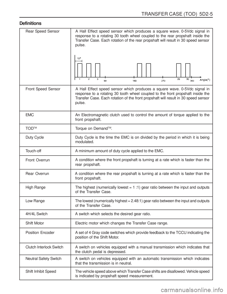
Rear Speed Sensor A Hall Effect speed sensor which produces a square wave. 0-5Vdc signal inresponse to a rotating 30 tooth wheel coupled to the rear propshaft inside the
Transfer Case. Each rotation of the rear propshaft will result in 30 speed sensor pulse.
Front Speed Sensor A Hall Effect speed sensor which produces a square wave. 0-5Vdc signal in response to a rotating 30 tooth wheel coupled to the front propshaft inside the
Transfer Case. Each rotation of the front propshaft will result in 30 speed sensor pulse.
EMC An Electromagnetic clutch used to control the amount of torque applied to the front propshaft.
TOD TM
Torque on DemandTM
.
Duty Cycle Duty Cycle is the time the EMC is on divided by the period in which it is being modulated.
Touch-off A minimum amount of duty cycle applied to the EMC.
Front OverrunA condition where the front propshaft is turning at a rate which is faster than the rear propshaft.
Rear Overrun A condition where the rear propshaft is turning at a rate which is faster than the
front propshaft.
High Range The highest (numerically lowest = 1 :1) gear ratio between the input and outputsof the Transfer Case.
Low Range The lowest (numerically highest = 2.48:1) gear ratio between the input and outputs
of the Transfer Case.
4H/4L Switch A switch which selects the desired gear ratio.
Shift Motor Electric motor which changes the Transfer Case range.
Position Encoder A set of 4 Gray code switches which provide feedback to the TCCU indicating theposition of the Shift Motor.
Clutch Interlock Switch A switch on vehicles equipped with a manual transmission which indicates that the clutch pedal is depressed.
Neutral Safety Switch A switch on vehicles equipped with an automatic transmission which indicatesthat the transmission is in neutral.
Shift Inhibit Speed The vehicle speed above which Transfer Case shifts are disallowed. Vehicle speedis indicated by propshaft speed measurement.
Page 1099 of 1574

5D2-10 TRANSFER CASE (TOD) Electric Shift System Operation
The Electric Shift System is responsible for changing the Transfer Case gear ratio by controlling the electric shift
motor. The TCCU monitors the 4H/4L switch, neutral switch, speed sensors, position encoder, and ignition switch. A range change is initiated when
1. The 4H/4L Switch is changed from 4H to 4L or from 4L to 4H.
2. The motor position (as indicated by the position encoder) does not match the 4H/4L Switch immediately after theignition is turned on.
1. Shift Criteria When a range change is initiated a Diagnostic Test will be completed on the motor, speed sensors, and position
encoder. If the Diagnostic Test fails, the shift will not be attempted. If all components are operating properly, theTCCU will attempt a range change after the following shift criteria are met:
a. The transmission is in neutral for 2 seconds after the shift is requested.
b. Both propshaft speeds are below 87 rpm (2580 pulses/minute).
If the transmission is taken out of neutral before 2 seconds has elapsed, or either propshaft speed increases above the limit, the shift will be suspended and the 4L Indicator will continue to blink until the criteria are met again or the 4H/4L Switch is returned to the original position.
2. Range Change When the shift criteria are met, the motor is rotated in the appropriate direction (as determined by the selectorswitch) until one of the following occurs:
a. The motor reaches its destination.
b. The motor is on for 5 seconds without reaching its destination. The shift has failed and the TCCU will respond as default mode.
c. A fault occurs with either the motor or position encoder. Refer to the diagnosis requirement.
When the motor is energized, the Ignition, 4H/4L Switch, propshaft speeds, and transmission neutral inputs are ignored.
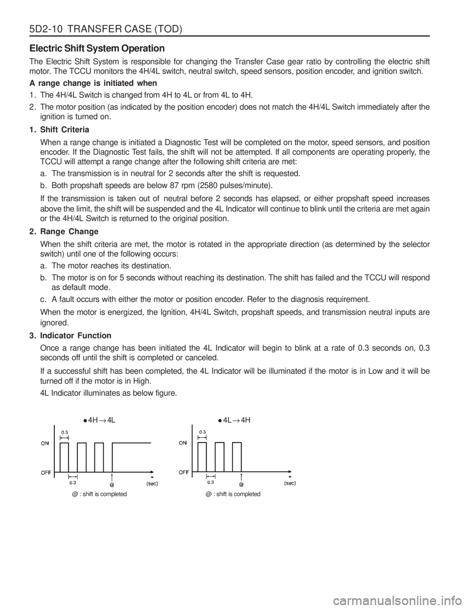
3. Indicator Function Once a range change has been initiated the 4L Indicator will begin to blink at a rate of 0.3 seconds on, 0.3 seconds off until the shift is completed or canceled.
If a successful shift has been completed, the 4L Indicator will be illuminated if the motor is in Low and it will be turned off if the motor is in High. 4L Indicator illuminates as below figure.
4H
� 4L
@ : shift is completed
4L
� 4H
@ : shift is completed
Page 1108 of 1574

TRANSFER CASE (TOD) 5D2-19
ClassificationEngine Type
Transmission/Vehicle Type Axle Ratio
Tire Size
Coding Required
1. Replacement of TOD control unit.
2. Adjustment by input error.
3. Change of tire specification.
Items
Gasoline Engine (E32) 661 Diesel Engine
661LA Diesel Turbo Engine
662 Diesel Engine
662LA Diesel Turbo Engine Manual Transmission
Automatic Transmission MUSSO
KORANDO 3.734.554.895.38 5.86
P215 P235P255P275
Coding Method
1. Check and record engine type, axle ratio and tire size.
2. Ignition “OFF ”.
3. Connect SCANNER with diagnosis connector in engine room.
4. Ignition “ON ”.
5. Read the current memorized specification in TOD control unit.
6. Compare memorized specification with the checked record. If not matched, perform a coding.
7. Read again memorized coding specification in TOD control unit for confirmation of coding.
8. Check coding specification whether it matches with vehicle or not. If not, perform a coding again.
Coding items
Page 1123 of 1574

5D2-34 TRANSFER CASE (TOD) TRANSFER CASE (TOD)
1 Transmission
2 TOD Transfer Case
3 Extension Housing
4 Bolt....................................................... 35-60Nm5 Front Propeller Shaft
6 Bolt
....................................................... 81-89Nm
7 Rear Propeller Shaft
8 Bolt ....................................................... 81-89Nm
Page 1124 of 1574

TRANSFER CASE (TOD) 5D2-35
Removal & Installation Procedure1. Disconnect (-) cable from battery.
2. Lift on vehicle and make sure on safety. NoticeBe careful for catalytic converter due to high temperature after driving or engine running.
3. Prepare a vessel to drain transfer case and manual transmission oil.
4. Release drain plug and drain transfer case and manual transmission oil. If planar damper is installed, unscrew 4 bolts and remove
the planar damper. NoticeOil drain should be along with whole transfer case
disassembly and assembly.
5. Disconnect transmission extension wiring connector back
side transfer case. Notice
When disconnect connector, make sure on direction of locking tab towards inside.
6. Disconnect shift motor/clutch coil connect (Black 7 pin) connector upper backside.
7. Disconnect front and rear speed sensor connector (white 7 pin).
8. Disconnect speedometer sensor connector right upper side.
9. Disconnect breather tube front upper side transfer case (upper connecting point of transfer case and front propeller).
10. Prepare hydraulic jack and support transfer case assembly.
Page 1125 of 1574

5D2-36 TRANSFER CASE (TOD)
11. Unscrew 4 units of M12 bolts from case flange thendisconnect front propeller shaft from transfer case. Installation Notice
Tightening Torque 81 - 89 Nm
12. Unscrew 4 units of M12 bolts from case flange then disconnect rear propeller shaft from transfer case. Installation Notice
13. Unscrew 5 units of mounting bolt (M12) from extension housing in transmission.Installation Notice
Tightening Torque 81 - 89 Nm
Tightening Torque 35 - 60 Nm
Notice Make sure the connecting surface is clean.Applying long-life grease spline inside transfer case input shaft.
14. Installation should follow the removal procedure in the reverse order.
Page 1136 of 1574

TRANSFER CASE (TOD) 5D2-47
Assembly Procedure Assembly
Before assembly, lubricate all parts with Automatic Transmission Fluid or equivalent.
1. If removed, drive the bearing into the front output case bore.Drive the bearing in staight, making sure it is not cocked in the bore. Install the internal snap ring that retains the bearing to the front case.
2. If removed, install the front yoke to flange seal in the front case bore.
3. If removed, install the yoke to flange seal into the mounting adapter bore.
4 Sun Gear
5 Thrust Plate
6 Input Shaft
7 Thrust Washer
8 Bearing
9 External Snap Ring
10 Internal Snap Ring
4. If the input shaft needle bearing and bushing were removed,
install a new bearing and bushing as detailed in the following steps: Press a new needle bearing, then a new bushing in the input shaft as follows:
a. Position the input shaft on Axle Bearing/Seal Plate or equivalent, and Pinion Bearing Cone Replacer as a
spacer.
b. Press a new needle bearing into the end of the input shaft until it seats in the input shaft.
c. Press in a new bushing.
5. The recessed face of the sun gear and the snap ring groove on the bearing outer race should be toward the rear of thetransfer case. The stepped face of the thrust washer shouldface toward the bearing.
Slide the sun gear, thr ust plate and thrust washer into
position on the input shaft. Press the bearing over the input shaft. Install the external snap ring to the input shaft.
Page 1137 of 1574

5D2-48 TRANSFER CASE (TOD)
6. Install the front planet to the sun gear and input shaft.Install the internal snap ring to the planetary carrier.
7. Place the tanged snap ring in the case. Expand snap ring with snap ring pliers and install planetary carrier assembly. Check installation by holding the case and carefully tappingthe face of the input shaft against a wooden block to makesure the snap ring is installed.
8. Remove all traces of gasket sealant from the front case and mounting adapter mating surfaces. Install a bead ofgasket sealant on the surface of the front case.
9. Install the high-low shift fork and high-low collar as an assembly into the front planet. Notice Make sure that the nylon wear pads are installed on the shift fork and snapped securely into place.
12 Rear Output Shaft
13 Oil Strainer
14 Coupling Hose
15 Hose Clamp
16 Pump Body
10. If new pump is used, align the flat of the output shaft and
the flat of the pump. Slide the pump onto the output shaft.
�Do not disassemble oil pump. It is serviced only as an
assembly. Check the pump to make sure the pump
rotates freely.
� Do not remove the plastic insert from the bore of the
new pump. Discard it after it slides out during pumpinstallation to the rear output shaft.
� While turning the output shaft, prime the pump through
the oil filter pickup tube or housing inlet hole with clean
Automatic Transmission Fluid or equivalent.
11. Inspect the outside surfaces and bore of the oil pump. If there is no discoloration in the pump housing, gear or cover,and the pump bore and the lube holes of the output shaft show evidence of oil, the pump is working.
Page 1142 of 1574

TRANSFER CASE (TOD) 5D2-53
40. Install the rear case flange on the output shaft. Install therubber seal, output shaft yoke washer and nut. Tighten the nut.
Tightening Torque 137 - 196 Nm
41. Install the drainplug and tighten.
42. Fill the transfer case with 1.4 liters of Automatic Transmission Fluid or equivalent. NoticeFluid level should be just below the filler plug hole.
Tightening Torque 19 - 30 Nm
Tightening Torque 19 - 30 Nm
43. Install the fill pulg and tighten.
44. Install the transfer case as outlined in removal and
Installation, transfer case in the section. NoticeMake sure proper drain and fill plugs are installed if case is replaced.
Page 1203 of 1574

SECTION 9A
BODY WIRING SYSTEM
Schematic and Routing Diagrams . . . . . . . . 9A-2
Power Distribution . . . . . . . . . . . . . . . . . . . . . . 9A-2
Starting & Charging (Gasoline HFM) . . . . . . . 9A-3
Starting & Charging (Diesel) . . . . . . . . . . . . . . 9A-4
Fuse Box and Relay . . . . . . . . . . . . . . . . . . . 9A-5
Location of Connectors by
Wiring Harness . . . . . . . . . . . . . . . . . . . . . 9A-7
Main . . . . . . . . . . . . . . . . . . . . . . . . . . . . . . . . 9A-7
Engine Room . . . . . . . . . . . . . . . . . . . . . . . . 9A-11
Floor . . . . . . . . . . . . . . . . . . . . . . . . . . . . . . . 9A-13
Roof . . . . . . . . . . . . . . . . . . . . . . . . . . . . . . . 9A-14
Driver's Door . . . . . . . . . . . . . . . . . . . . . . . . . 9A-15
Passenger's Door . . . . . . . . . . . . . . . . . . . . . 9A-15
TABLE OF CONTENTS
Caution: Disconnect the negative battery cable before removing or installing any electrical unit or when a tool or equipment could easily come in contact with exposed electrical terminals. Disconnecting this cable will help prevent personal injury and damage to the vehicle. The ignition must also be in LOCK unless otherwisenoted.
Rear Left Door . . . . . . . . . . . . . . . . . . . . . . . 9A-16
Rear Right Door . . . . . . . . . . . . . . . . . . . . . . 9A-16
Tail Gate . . . . . . . . . . . . . . . . . . . . . . . . . . . . 9A-17
Semi Automatic Air Conditioner . . . . . . . . . . 9A-18
Full automatic Air Conditioner . . . . . . . . . . . . 9A-19
Gasoline Engine (MSE) . . . . . . . . . . . . . . . . 9A-20
Gasoline Engine (HFM) . . . . . . . . . . . . . . . . 9A-21
Diesel Engine . . . . . . . . . . . . . . . . . . . . . . . . 9A-22
Manual Transmission . . . . . . . . . . . . . . . . . . 9A-23
Automatic Transmission (BENZ) . . . . . . . . . . 9A-24
Automatic Transmission (BTRA) . . . . . . . . . . 9A-25
Driver's Seat . . . . . . . . . . . . . . . . . . . . . . . . . 9A-26