brake SSANGYONG MUSSO 2003 Owner's Manual
[x] Cancel search | Manufacturer: SSANGYONG, Model Year: 2003, Model line: MUSSO, Model: SSANGYONG MUSSO 2003Pages: 1574, PDF Size: 26.41 MB
Page 703 of 1574

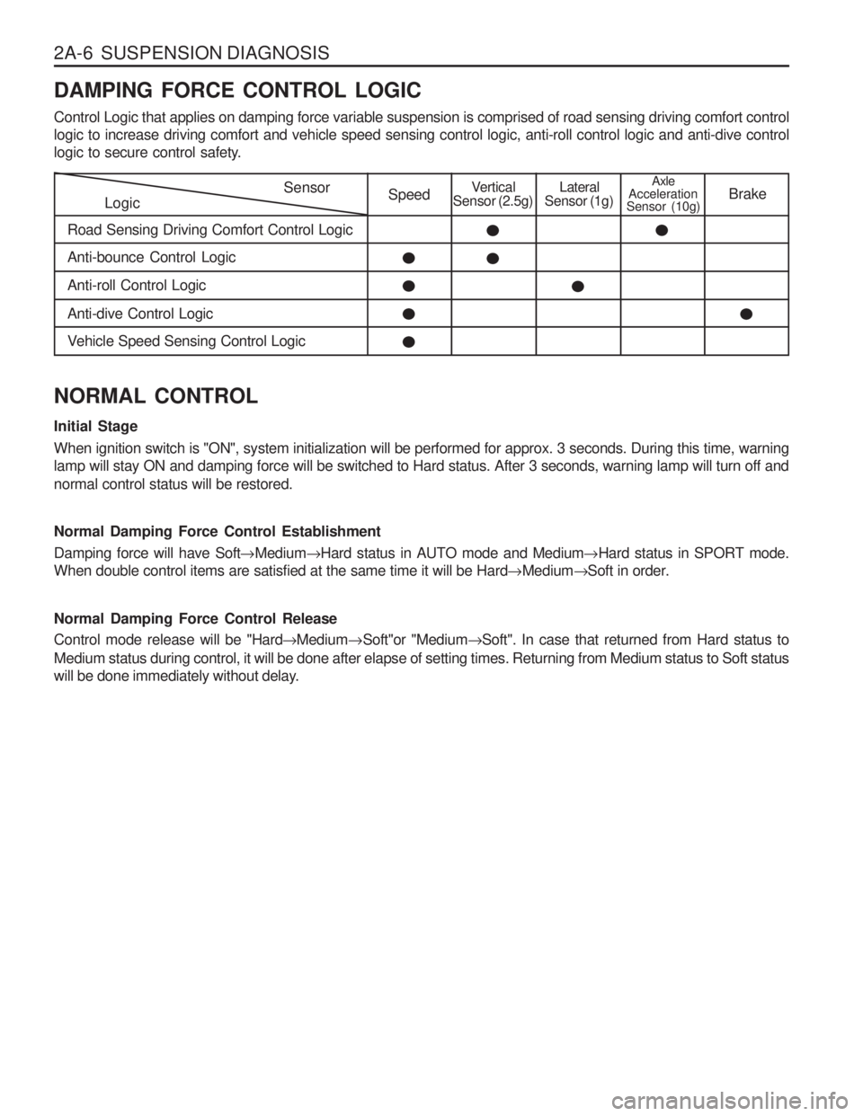
2A-6 SUSPENSION DIAGNOSIS DAMPING FORCE CONTROL LOGIC Control Logic that applies on damping force variable suspension is comprised of road sensing driving comfort control logic to increase driving comfort and vehicle speed sensing control logic, anti-roll control logic and anti-dive control
logic to secure control safety.
LogicSensor
Road Sensing Driving Comfort Control LogicSpeedVertical
Sensor (2.5g)Lateral
Sensor (1g)Axle
Acceleration
Sensor (10g) Brake
Anti-bounce Control Logic Anti-roll Control LogicAnti-dive Control Logic
Vehicle Speed Sensing Control Logic
NORMAL CONTROL Initial Stage When ignition switch is "ON", system initialization will be performed for approx. 3 seconds. During this time, warning lamp will stay ON and damping force will be switched to Hard status. After 3 seconds, warning lamp will turn off and normal control status will be restored. Normal Damping Force Control Establishment Damping force will have Soft �Medium �Hard status in AUTO mode and Medium �Hard status in SPORT mode.
When double control items are satisfied at the same time it will be Hard �Medium �Soft in order.
Normal Damping Force Control Release Control mode release will be "Hard �Medium �Soft"or "Medium �Soft". In case that returned from Hard status to
Medium status during control, it will be done after elapse of setting times. Returning from Medium status to Soft status
will be done immediately without delay.
Page 708 of 1574

SUSPENSION DIAGNOSIS 2A-11
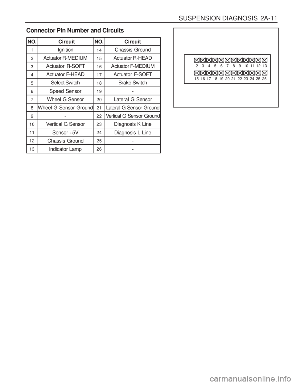
Connector Pin Number and Circuits
2
15
3
16
4
17
5
18
6
19
7
20
8
21
9
22
10
23
11
24
12
25
13
26
Ignition
Actuator R-MEDIUM Actuator R-SOFT
Actuator F-HEAD Select Switch
Speed Sensor
Wheel G Sensor
Wheel G Sensor Ground
-
Vertical G Sensor
Sensor +5V
Chassis Ground Indicator Lamp
NO. CircuitNO. Circuit
1 14
21 5
316
417
518
619
720
821
922
10 23
11 2 4
12 25
13 26 Chassis Ground
Actuator R-HEAD
Actuator F-MEDIUM
Actuator F-SOFT Brake Switch
-
Lateral G Sensor
Lateral G Sensor Ground
Vertical G Sensor Ground Diagnosis K Line
Diagnosis L Line - -
Page 713 of 1574

WHEEL ALIGNMENT 2B-3
3. Road test the vehicle. If there is improvement, installthe original tires to find the offending tire. If there is no a straight improvement, install good tires in place of all four offending tires.
4. Install original tires one at a time to find the offending tire.
RADIAL TIRE LEAD/PULL Lead/pull is the deviation of the vehicle from a straight path on a level road with no pressure on the steeringwheel. Lead is usually caused by:
� Incorrect alignment.
� Uneven brake adjustment.
� Tire construction.
The way in which a tire is built can produce lead/pull in
the vehicle.011-center belts on radial tires can causethe tire to develop a side force while the vehicle rolls straight down the road. If one side of the tire has even a little larger diameter than the diameter of the other side,the tire will tend to roll to one side. Unequal diameterswill cause the tire to develop a side force which canproduce vehicle lead/pull. The radial lead/pull diagnosis chart should be used to determine whether the problem originates from an alignment problem or from the tires. Part of the leaddiagnosis procedure calls for tire rotation that is differentfrom the proper tire rotation pattern. If a medium- to high-mileage tire is moved to the other side of the vehicle, be sure to check for ride roughness. Rear tires will not cause lead/pull.
Page 714 of 1574

2B-4 WHEEL ALIGNMENT1. Perform wheel alignment preliminary inspection.
2. Check the brakes for dragging.
3. Road test the vehicle.Does the vehicle lead/pull?
1. Cross switch the front tire and wheel assemblies. 2. Road test the vehicle. Does the vehicle lead/pull? 1. Check the front wheel alignment. Is the alignment within specifications?
1. Compare the front camber and front caster to specifications.Are they within specifications?
1. Check the vehicle frame. Is the frame bent?
1. Straighten the frame. Is the repair complete?
1. The probable cause is the tires.
2. Switch the left front tire and wheel assembly with
the left rear tire and wheel assembly.
3. Road test the vehicle. Does the vehicle still lead/pull?
1. Switch the left front tire and wheel assembly with the left rear tire and wheel assembly and replace theleft front tire. Does the repair complete?
1. Switch the right front tire and wheel assembly with
the right rear tire and wheel assembly.
2. Road test the vehicle. Does the vehicle still lead/pull?
1. Switch the right front tire and wheel assembly with the right rear tire and wheel assembly and replace the right front tire. Is the repair complete? Action
Radial Tire Lead/Pull Diagnosis Chart
Step
1Values(s)
- Ye s
Go to Step 2
Go to Step 3
Go to Step 4
Go to Step 7
Go to Step 6
Go to Step 3
Go to Step 9
System OK
Go to Step 1
System OK No
System OK System OK Adjust
alignment
Go to Step 5
Go to Step 1
-
Go to Step 8
Go to Step 1
Go to Step 10
Go to Step 1
2 345 6 7 8 9
10 - - - - - - - - -
Page 715 of 1574

WHEEL ALIGNMENT 2B-5
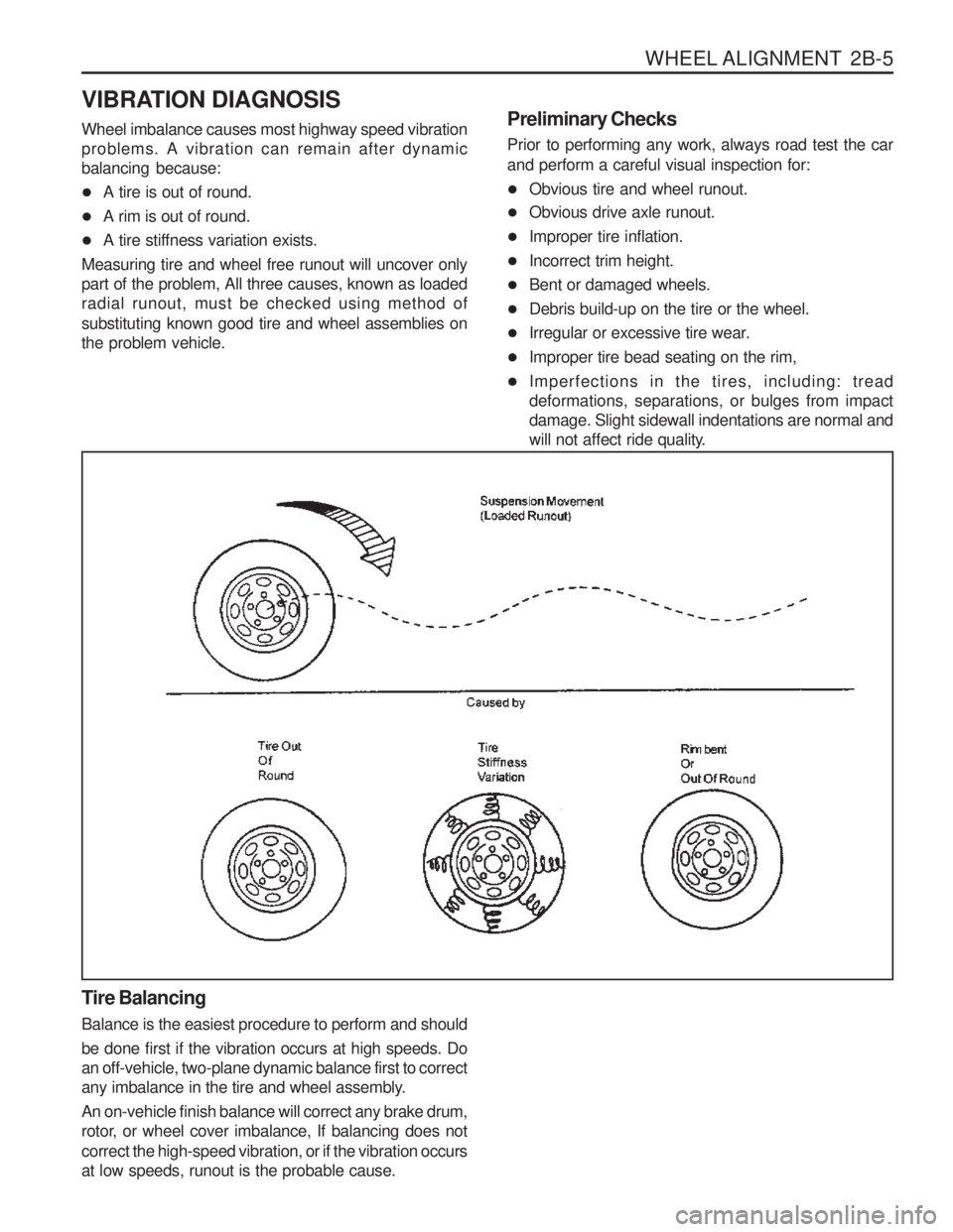
VIBRATION DIAGNOSIS Wheel imbalance causes most highway speed vibration problems. A vibration can remain after dynamicbalancing because:
�A tire is out of round.
� A rim is out of round.
� A tire stiffness variation exists.
Measuring tire and wheel free runout will uncover only part of the problem, All three causes, known as loadedradial runout, must be checked using method of substituting known good tire and wheel assemblies on the problem vehicle. Preliminary Checks Prior to performing any work, always road test the car and perform a careful visual inspection for:
�
Obvious tire and wheel runout.
� Obvious drive axle runout.
� Improper tire inflation.
� Incorrect trim height.
� Bent or damaged wheels.
� Debris build-up on the tire or the wheel.
� Irregular or excessive tire wear.
� Improper tire bead seating on the rim,
� Imperfections in the tires, including: tread deformations, separations, or bulges from impactdamage. Slight sidewall indentations are normal and
will not affect ride quality.
Tire Balancing Balance is the easiest procedure to perform and should be done first if the vibration occurs at high speeds. Do an off-vehicle, two-plane dynamic balance first to correct
any imbalance in the tire and wheel assembly. An on-vehicle finish balance will correct any brake drum,
rotor, or wheel cover imbalance, If balancing does not correct the high-speed vibration, or if the vibration occurs at low speeds, runout is the probable cause.
Page 721 of 1574

2C-2 FRONT SUSPENSIONApplication
Torque Arm Bolt N
�m
40 - 60 60 - 80
FASTENER TIGHTENING SPECIFICATIONS
Stabilizer Bar
Application
Stabilizer Bar Retaining Nut Stabilizer Bar Link NutLower Arm Nut N
�m
30 - 45 60 - 80 16 - 22
Torsion Bar
Lower and Upper Arm
Application
Upper Arm Nut Upper Arm End Castle NutLower Arm Nut Lower Arm End Castle Nut N
�m
120 - 140 80 - 150
150 - 180 120 - 180
Steering Knuckle and Drive Shaft
Application
Brake Caliper Hose Bolt Brake Caliper Mounting Bolt
Tie Rod Retaining Nut Upper Arm Retaining NutLower Arm Retaining Nut N
�m
25 - 35
85 - 105 35 - 45
80 - 150
120 - 180
M10 M12
Page 733 of 1574

2C-14 FRONT SUSPENSION ECS (ECU)1 Electronically Controlled Suspension (ECU)
2 Connector
3 Bolts (2 pieces)
Removal & Installation Procedure
1. Disconnect each connectors from the console box and remove the console box.
2. Disconnect ECU connector.
3. Unscrew 10mm x 2 bolts and remove ECS (ECU).
4. Installation should follow the removal procedure in the reverse order.
4 Parking Brake Lever
5 Over Voltage Protection Relay
Page 740 of 1574

REAR SUSPENSION 2D-7
�Shock Absorber.
1. Remove the lower mounting nut.
Installation Notice
2. Remove the upper mounting nut and remove the shock absorber. Installation Notice
Tightening Torque 50 - 65 Nm
� Upper Arm
1. Remove the upper arm fixing nut from the frame.
Installation Notice
2. Remove the upper arm fixing nut from the rear axle and remove the upper arm. Installation Notice
Tightening Torque 150 - 180 Nm
Tightening Torque 150 - 180 Nm
�Lower arm
1. Remove the parking brake cable bracket.
Tightening Torque 30 - 45 Nm
Distance between the nut
end and the screw end 6 - 9 mm
Page 753 of 1574

FRONT DRIVE AXLE 3A-3
1 Drive Shaft
2 Axle Housing Mounting Bolt
3 Axle Housing
4 Cross MemberCOMPONENT LOCATOR
FRONT AXLE5 Brake Disc
6 Hub-Wheel
7 Locking Hub
Page 759 of 1574

FRONT DRIVE AXLE 3A-9
Removal & Installation Procedure
1. Remove the tire.Installation Notice
Steel Wheel
Aluminum Wheel
Tightening Torque80 - 120 Nm
110 - 130 Nm
2. Remove the autolocking hub vacuum hose.
3. With ABS Remove the wheel speed sensor from the steering knuckle. Installation Notice
4. Remove the mounting bolts and pull off the caliper assembly. Installation Notice
Tightening Torque 6 - 8 Nm
Hose Bolt
Mounting Bolt
Tightening Torque25 - 35 Nm
85 - 105 Nm
Notice Be careful not to damage the brake hose.