ad blue SSANGYONG MUSSO 2003 Service Manual
[x] Cancel search | Manufacturer: SSANGYONG, Model Year: 2003, Model line: MUSSO, Model: SSANGYONG MUSSO 2003Pages: 1574, PDF Size: 26.41 MB
Page 85 of 1574

M162 ENGINE MECHANICAL 1B1-49
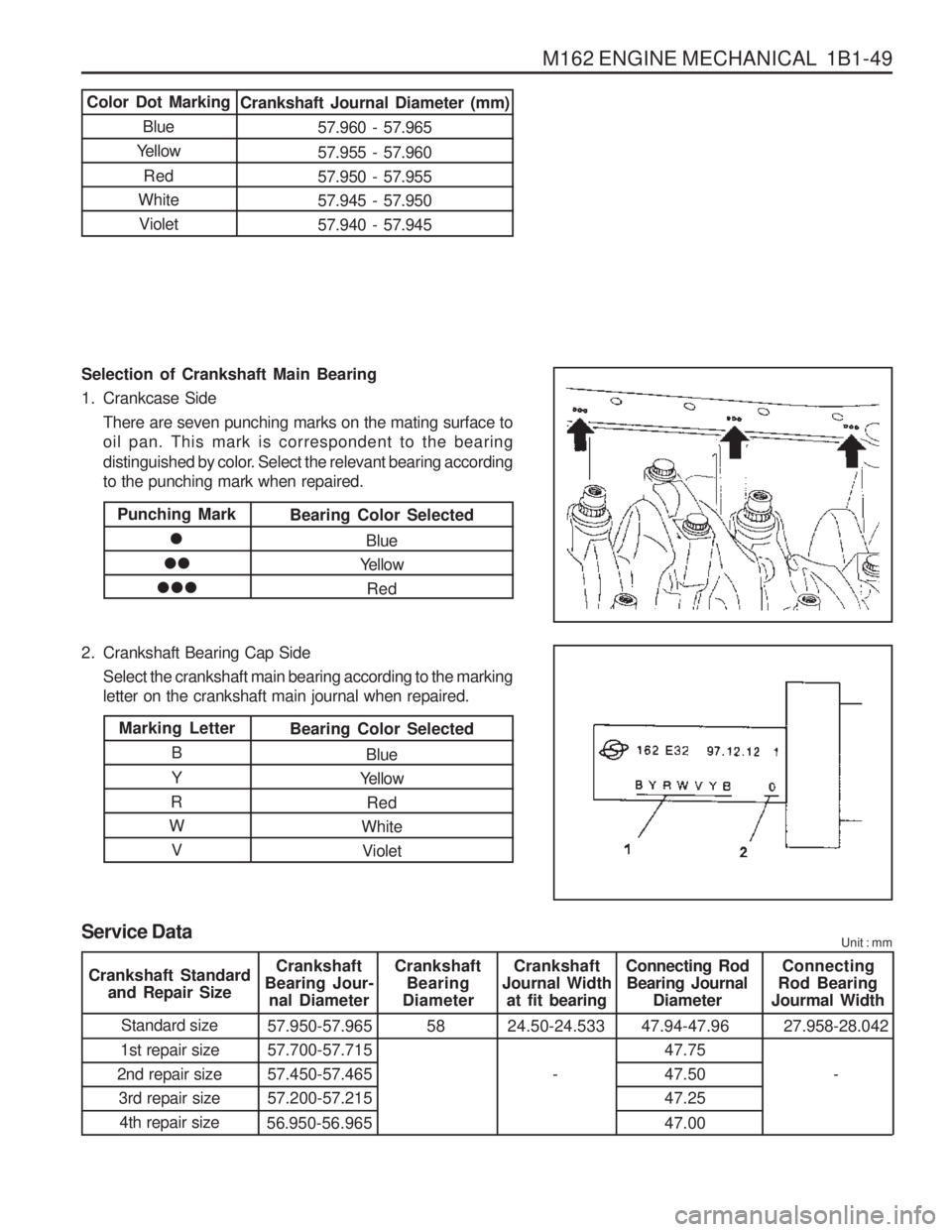
Selection of Crankshaft Main Bearing
1. Crankcase SideThere are seven punching marks on the mating surface to oil pan. This mark is correspondent to the bearing
distinguished by color. Select the relevant bearing according to the punching mark when repaired.
2. Crankshaft Bearing Cap Side Select the crankshaft main bearing according to the markingletter on the crankshaft main journal when repaired.
Color Dot Marking
Blue
Yellow
Red
White VioletCrankshaft Journal Diameter (mm)
57.960 - 57.965 57.955 - 57.960 57.950 - 57.95557.945 - 57.95057.940 - 57.945
Punching Mark
Bearing Color Selected
Blue
Yellow
Red
Marking Letter
B Y
R
W VBearing Color Selected
Blue
Yellow
Red
White Violet
Service Data Unit : mm
Crankshaft
Bearing Jour- nal Diameter Crankshaft
Bearing
Diameter Crankshaft
Journal Width at fit bearing Connecting Rod
Bearing Journal Diameter Connecting
Rod Bearing
Jourmal Width
Standard size
1st repair size
2nd repair size 3rd repair size4th repair size 57.950-57.965 57.700-57.71557.450-57.46557.200-57.215
56.950-56.965 58 24.50-24.533
-47.94-47.96
47.7547.5047.25 47.00 27.958-28.042
-
Crankshaft Standard
and Repair Size
Page 208 of 1574

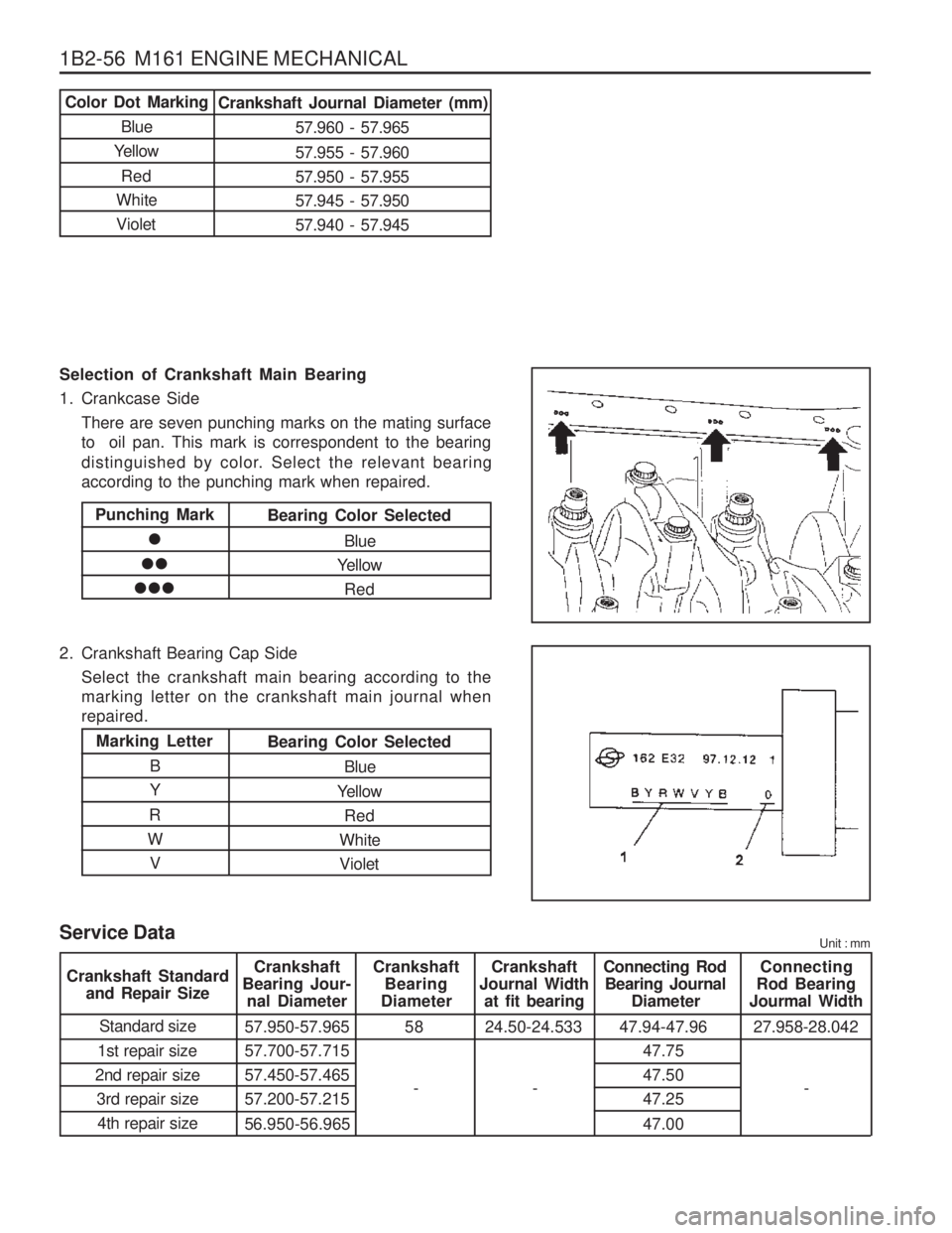
1B2-56 M161 ENGINE MECHANICAL Selection of Crankshaft Main Bearing
1. Crankcase SideThere are seven punching marks on the mating surface to oil pan. This mark is correspondent to the bearing
distinguished by color. Select the relevant bearing according to the punching mark when repaired.
2. Crankshaft Bearing Cap Side Select the crankshaft main bearing according to themarking letter on the crankshaft main journal whenrepaired.
Color Dot Marking
Blue
Yellow
Red
White VioletCrankshaft Journal Diameter (mm)
57.960 - 57.965 57.955 - 57.960 57.950 - 57.95557.945 - 57.95057.940 - 57.945
Punching Mark
Bearing Color Selected
Blue
Yellow
Red
Marking Letter
B Y
R
W VBearing Color Selected
Blue
Yellow Red
White Violet
Service Data Unit : mm
Crankshaft
Bearing Jour- nal Diameter Crankshaft
Bearing
Diameter Crankshaft
Journal Width at fit bearing Connecting Rod
Bearing Journal Diameter Connecting
Rod Bearing
Jourmal Width
Standard size
1st repair size
2nd repair size 3rd repair size4th repair size 57.950-57.965 57.700-57.71557.450-57.46557.200-57.215
56.950-56.965 58 24.50-24.533 47.94-47.96
47.75 47.5047.25 47.0027.958-28.042
Crankshaft Standard
and Repair Size
-
--
Page 290 of 1574

OM600 ENGINE MECHANICAL 1B3-25
6. Pull off the tensioning lever (4) from guide rail pin.
7. Remove the spring (17).Installation NoticeInsert spring (17) with color coding (blue/violet) facing up.
8. Pry off the closing cover (12) and remove the socket bolt(11) and then remove the tensioning pulley (10). Installation Notice
Tightening Torque 29 Nm
9. Pry off the closing cover (16) and remove the fit bolt (15).
10. Remove the tensioning lever (14) and washer (13).
11. Clean thread in the timing case cover and fit bolt.
Installation Notice Apply Loctite on thread of fit bolt.
Tightening Torque 100 Nm
12. Installation should follow the removal procedure in the reverse order.
Page 352 of 1574

OM600 ENGINE MECHANICAL 1B3-87
bearing shell
Matching Crankshaft Bearing Shells to Basic Bearing Bore in Crankshaft Matching Crankshaft Bearing Shells to Basic Bearing Journal of Crankshaft
Marking of basic bearing bore in lowerColor code of relevant crankshaft
parting surface 1 punch mark or blue
2 punch marks or yellow 3 punch marks or red bearing shell
Blue or white-blue
Yellow or white-yellowRed or white-red
Marking of bearing journals on crank websColor code of relevant crankshaft
Blue or white-blue
Yellow or white-blue Red or white-blue Blue or white-blue
Yellow or white-yellow Red or white-red
Page 611 of 1574

M162 ENGINE CONTROLS 1F1-79
Accelerator Pedal Sensor Connector(Sensor Side)
Potentiometer 1.Pin no. 3 :Red
Pin no. 1 :YellowPin no. 5 :Brown
Potentiometer 2. Pin no. 6 :VioletPin no. 4 :GreenPin no. 2 :White
Accelerator Pedal Sensor Connector(Vehicle Side)
Potentiometer 1.Pin no. 3 :Red-Black Pin no. 1 :Blue-Green
Pin no. 5 :Yellow-Green
Potentiometer 2. Pin no. 6 :GreenPin no. 4 :Blue-RedPin no. 2 :LightGreen
Function Potentiometer 1, Power Supply(+)
Potentiometer 1, Signal
Potentiometer 2, Ground
Potentiometer 2, Power Supply(+)
Pin no. 3 Pin no. 1 Pin no. 5 Pin no. 6
Pin no. 4 Pin no. 2Potentiometer 2, SignalPotentiometer 2, Ground
Circuit Diagram
Potentiometer 1. Potentiometer 2.
Page 772 of 1574

3A-22 FRONT DRIVE AXLE
Inspection of Ring Gear Tooth Contact Pattern Normal Contact Apply gear-marking compound (prussian blue / red lead) on the ring gear teeth. Rotate the ring gear and check the tooth contact pattern. Abnormal Contact
Tooth Contact pattern Possible CauseRemedy
1. Heel Contact
2. Toe Contact
3. Face Contact
4. Flank ContactInsufficient backlash (little)
�
Tooth can be damaged or broken under heavy load
Excessive backlash (much)
� Drive pinion shaft is apart from the ring gear
� Noise can be occurred
Insufficient backlash (much)
� Gear contacts on the low flank
� Gear can be damaged orworn
� Noise can be occurred Adjust backlash(Decrease backlash)
�
Select proper shim(s) to move the drive pinion toward the ring gear (toward toe)
Adjust backlash(Increase backlash)
� Select proper shim(s) to move the drive pinion against the ring gear (toward heel)
Adjust backlash(Increase pinion shim)
� Move the drive pinion toward the ring gear (toward center of ring gear)
Adjust backlash(Decrease pinion shim)
� Move the ring gear toward the drive pinion (toward ring gear center line)
Excessive backlash (little)
�
Noise can be occurred
Page 795 of 1574

REAR DRIVE AXLE 3D-15
Inspection of Ring Gear Tooth Contact Pattern Normal Contact Apply gear-marking compound (prussian blue / red lead) on the ring gear teeth. Rotate the ring gear and check the tooth contact pattern. Abnormal Contact
Tooth Contact pattern Possible CauseRemedy
1. Heel Contact
2. Toe Contact
3. Face Contact
4. Flank ContactInsufficient backlash (little)
�
Tooth can be damaged or broken under heavy load
Excessive backlash (much)
� Drive pinion shaft is apart from the ring gear
� Noise can be occurred
Insufficient backlash (much)
� Gear contacts on the low flank
� Gear can be damaged orworn
� Noise can be occurred Adjust backlash(Decrease backlash)
�
Select proper shim(s) to move the drive pinion toward the ring gear (toward toe)
Adjust backlash(Increase backlash)
� Select proper shim(s) to move the drive pinion against the ring gear (toward heel)
Adjust backlash(Increase pinion shim)
� Move the drive pinion toward the ring gear (toward center of ring gear)
Adjust backlash(Decrease pinion shim)
� Move the ring gear toward the drive pinion (toward ring gear center line)
Excessive backlash (little)
�
Noise can be occurred
Page 884 of 1574

AUTOMATIC TRANSMISSION 5A-25
producing a low resistance.
Temperature/Resistance characteristics and location within the solenoid wiring loom are given in tables 3-1 and 3- 2, and figures 3.2 and 3.3.
If the transmission sump temperature exceeds 135°C, the TCU will impose converter lock-up at lower vehicle
speeds and in some vehicles flashes the mode indicator lamp. This results in maximum oil flow through the
external oil cooler and eliminates slippage in the torque converter. Both these actions combine to reduce the oil
temperature in the transmission.
Connects To
Solenoid 1 Solenoid 2Solenoid 3Solenoid 4Solenoid 5 Solenoid 6 Solenoid 7Solenoid 5
Temp Sensor
Temp SensorWire Color Red
Blue
Yellow
Orange GreenViolet
Brown
Green White WhitePin No.
1 2345 6 789
10
Table 3.2 - Pin No. Codes for Temperature Sensor Location In Solenoid Loom
Figure 3.3 - Temperature Sensor Location in Solenoid Loom
Page 1345 of 1574

MUSSO-SPORTS 1A-33
SUPPLEMENT
a. CONNECTOR INFORMATION
b. CONNECTOR IDENTIFICATION SYMBOL & PIN NUMBER POSITION
C351
W/H DRIVER
DOOR
C103
W/H MAIN
C101
W/H MAIN
C361
W/H CO-DRIVER
DOOR TWEETER
12345 678910
11 12 13 14 15 16 17 18 19 20 21
68 9
34
5 2
1
11 7
12 13 14
10
16 1720 21 22 18 19
15
68 9
34
5 2
1
11 7
12 13 14
10
16 1720 21 22 18 19
15
Main - Engine Main - Engine Main - Driver DoorMain - Co-Driver Door Main MainMain
C101 (21Pin, Colorless) C103 (2Pin, White) C351 (22Pin, Blue)C361 (22Pin, White) S201 (Black) S202 (Black)G203 Inside The Engine Room Fuse BlockInside The Engine Room Fuse BlockUpper The I/P Fuse Block Inside Co-Driver Side Cowl Panel Behind The ClusterUnder Right The Audio Right The I/P Fuse Block
CONNECTOR(NUMBER)
CONNECTING. WIRING HARNESSCONNECTOR POSITION
12
1234 5678
9 101112
13 14 15 16
Page 1350 of 1574

HOW TO USE ELECTRICAL WIRING DIAGRAM 1-3
Connector DiodeFuse in engine room fuse & relay box Fuse in passenger room fuse box Ground Joint - Inline wire connected point Splice pack(Junction connector)
C D
Ef F
G J
S
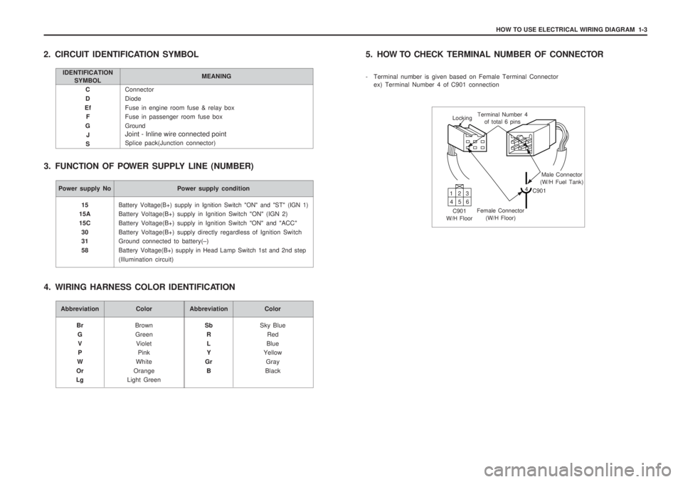
2. CIRCUIT IDENTIFICATION SYMBOL
3. FUNCTION OF POWER SUPPLY LINE (NUMBER)
IDENTIFICATION SYMBOL MEANING
Power supply No Power supply condition
Battery Voltage(B+) supply in Ignition Switch "ON" and "ST" (IGN 1)
Battery Voltage(B+) supply in Ignition Switch "ON" (IGN 2) Battery Voltage(B+) supply in Ignition Switch "ON" and "ACC"Battery Voltage(B+) supply directly regardless of Ignition Switch Ground connected to battery(
–)
Battery Voltage(B+) supply in Head Lamp Switch 1st and 2nd step
(Illumination circuit)
15
15A 15C
30 31 58
Abbreviation Color
BrownGreen Violet Pink
White
Orange
Light Green
Br
GV P
W
Or
LgAbbreviation Color
Sky BlueRed
Blue
Yellow
Gray
Black
Sb
RL Y
Gr B
4. WIRING HARNESS COLOR IDENTIFICATION 5. HOW TO CHECK
TERMINAL NUMBER OF CONNECTOR
- Terminal number is given based on Female Terminal Connector ex) Terminal Number 4 of C901 connection
Locking Terminal Number 4
of total 6 pins
Male Connector
(W/H Fuel Tank)
4 C901
Female Connector (W/H Floor)
C901
W/H Floor 13
2
46 5