engine SSANGYONG MUSSO 2003 Owner's Manual
[x] Cancel search | Manufacturer: SSANGYONG, Model Year: 2003, Model line: MUSSO, Model: SSANGYONG MUSSO 2003Pages: 1574, PDF Size: 26.41 MB
Page 28 of 1574
GENERAL ENGINE INFORMATION 1A1-9
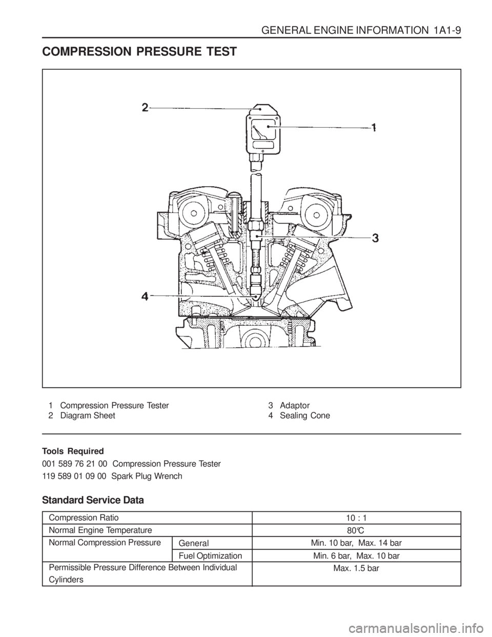
COMPRESSION PRESSURE TEST
1 Compression Pressure Tester
2 Diagram Sheet3 Adaptor
4 Sealing Cone
Tools Required
001 589 76 21 00 Compression Pressure Tester
119 589 01 09 00 Spark Plug Wrench Standard Service Data
Compression Ratio
Normal Engine TemperatureNormal Compression Pressure Permissible Pressure Difference Between Individual Cylinders
10 : 180°C
Min. 10 bar, Max. 14 bar
Min. 6 bar, Max. 10 bar Max. 1.5 bar
General Fuel Optimization
Page 29 of 1574
1A1-10 GENERAL ENGINE INFORMATION Measuring Procedure
1. Warm the engine up to normal operating temperature.
2. Remove the spark plugs.
3. Place the diagram sheet to compression pressuretester.
4. Connect the adaptor to compression pressure tester and install it into the spark plug hole.
5. Crank the engine approx. eight revolutions by using the start motor.
6. Compare the measurements of compression pressure tester with the specifications.
7. Measure the compression pressure of the other cylinders in the same way.
8. If measured value is not within the specifications, perform the cylinder pressure leakage test. Notice
� Discharge the combustion residues in the cylinders
before testing the compression pressure.
� Apply the parking brake before cranking the
engine.
Page 30 of 1574
GENERAL ENGINE INFORMATION 1A1-11
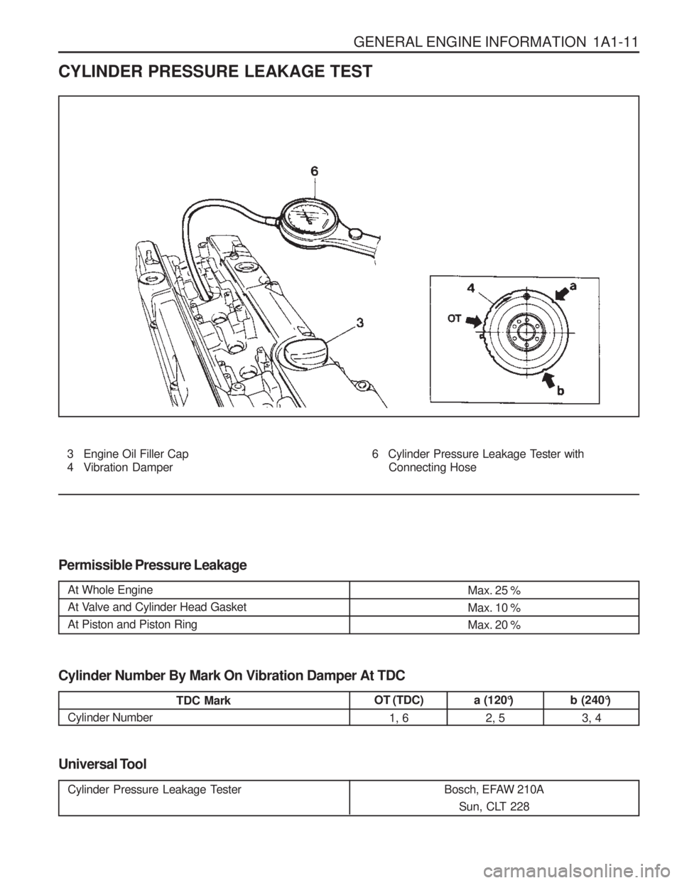
CYLINDER PRESSURE LEAKAGE TEST
3 Engine Oil Filler Cap
4 Vibration Damper
Permissible Pressure Leakage 6 Cylinder Pressure Leakage T
ester with
Connecting Hose
Universal Tool
At Whole Engine
At Valve and Cylinder Head GasketAt Piston and Piston RingMax. 25 % Max. 10 %Max. 20 %
Cylinder Number By Mark On Vibration Damper At TDC
TDC Mark
Cylinder Numberb (240°)
3, 4a (120°)2, 5
OT (TDC)
1, 6
Cylinder Pressure Leakage Tester Bosch, EFAW 210A
Sun, CLT 228
Page 31 of 1574
1A1-12 GENERAL ENGINE INFORMATION
Leakage Test1. Warm the engine up to normal operating temperature.
2. Disconnect the negative battery cable.
3. Remove the spark plugs.
4. Check the coolant level by opening the coolant surge tank cap and replenish if insufficient.
5. Open the engine oil filler cap.
6. Connect the tester to air pressure line and adjust the scale of tester.
7. Install the connecting hose to spark plug hole.
9. Connect the connecting hose to tester and measure the leakage volume after blowing up 5bar of compressed air. Notice Measure the leakage volume in the completely opening condition of throttle valve by pulling the acceleration cable.
10. Perform the pressure test according to the firing order.
Notice Firing Order : 1 - 5 - 3 - 6 - 2 - 4
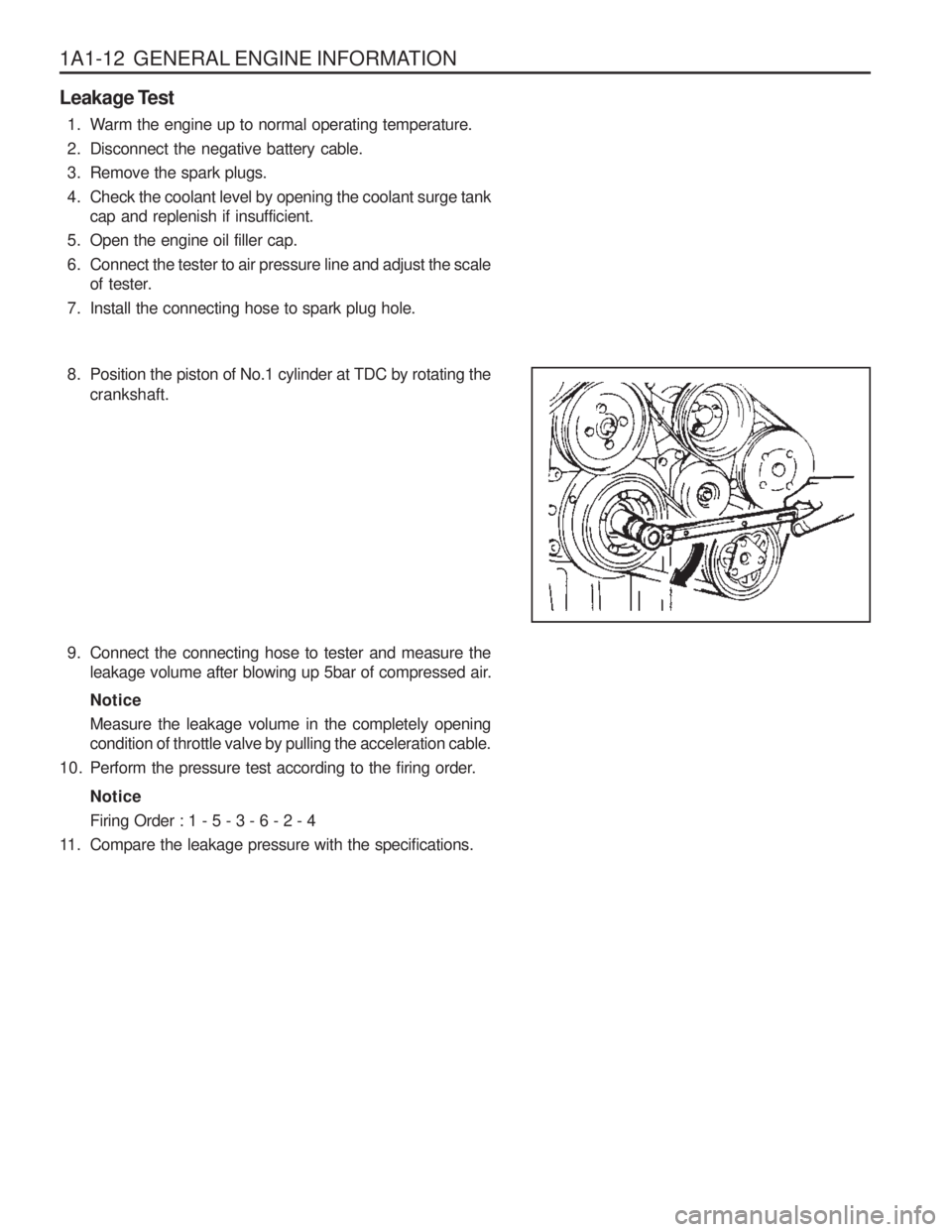
11. Compare the leakage pressure with the specifications. 8. Position the piston of No.1 cylinder at TDC by rotating the
crankshaft.
Page 32 of 1574
GENERAL ENGINE INFORMATION 1A1-13
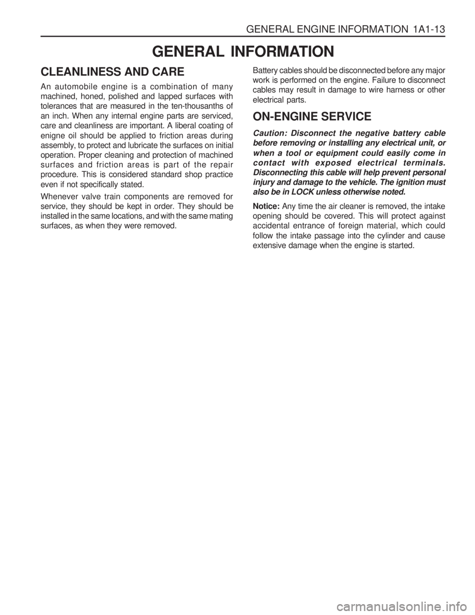
GENERAL INFORMATION
CLEANLINESS AND CARE An automobile engine is a combination of many machined, honed, polished and lapped surfaces withtolerances that are measured in the ten-thousanths ofan inch. When any internal engine parts are serviced,care and cleanliness are important. A liberal coating of enigne oil should be applied to friction areas during
assembly, to protect and lubricate the surfaces on initialoperation. Proper cleaning and protection of machinedsurfaces and friction areas is part of the repairprocedure. This is considered standard shop practice even if not specifically stated. Whenever valve train components are removed for
service, they should be kept in order. They should beinstalled in the same locations, and with the same matingsurfaces, as when they were removed. Battery cables should be disconnected before any majorwork is performed on the engine. Failure to disconnectcables may result in damage to wire harness or other electrical parts. ON-ENGINE SERVICE Caution: Disconnect the negative battery cable before removing or installing any electrical unit, or when a tool or equipment could easily come in contact with exposed electrical terminals.Disconnecting this cable will help prevent personalinjury and damage to the vehicle. The ignition mustalso be in LOCK unless otherwise noted. Notice:
Any time the air cleaner is removed, the intake
opening should be covered. This will protect against accidental entrance of foreign material, which could follow the intake passage into the cylinder and cause extensive damage when the engine is started.
Page 33 of 1574
SECTION 1
ENGINE
SECTION 1A2(M161 ENGINE)
GENERAL ENGINE INFORMATION TABLE OF CONTENTS
Specifications . . . . . . . . . . . . . . . . . . . . . . . 1A2-1
Engine Specifications . . . . . . . . . . . . . . . . . . 1A2-1
Component Locator . . . . . . . . . . . . . . . . . . 1A2-3
Front View . . . . . . . . . . . . . . . . . . . . . . . . . . 1A2-3
Side View . . . . . . . . . . . . . . . . . . . . . . . . . . . 1A2-4
Performance Curve . . . . . . . . . . . . . . . . . . 1A2-5
E23 Engine . . . . . . . . . . . . . . . . . . . . . . . . . . 1A2-5
E20 Engine . . . . . . . . . . . . . . . . . . . . . . . . . . 1A2-6
Special Tools . . . . . . . . . . . . . . . . . . . . . . . 1A2-7
Special Tools Table . . . . . . . . . . . . . . . . . . . . 1A2-7Diagnosis . . . . . . . . . . . . . . . . . . . . . . . . . .
1A2-8
Oil Leak Diagnosis . . . . . . . . . . . . . . . . . . . . 1A2-8
Engine Cranking At The Front of Crankshaft . . . . . . . . . . . . . . . . . . 1A2-9
Compression Pressure Test . . . . . . . . . . . . 1A2-10
Cylinder Pressure Leakage Test . . . . . . . . . 1A2-12
General Information . . . . . . . . . . . . . . . . . 1A2-14
Cleanliness and Care . . . . . . . . . . . . . . . . . 1A2-14
On-Engine Service . . . . . . . . . . . . . . . . . . . 1A2-14
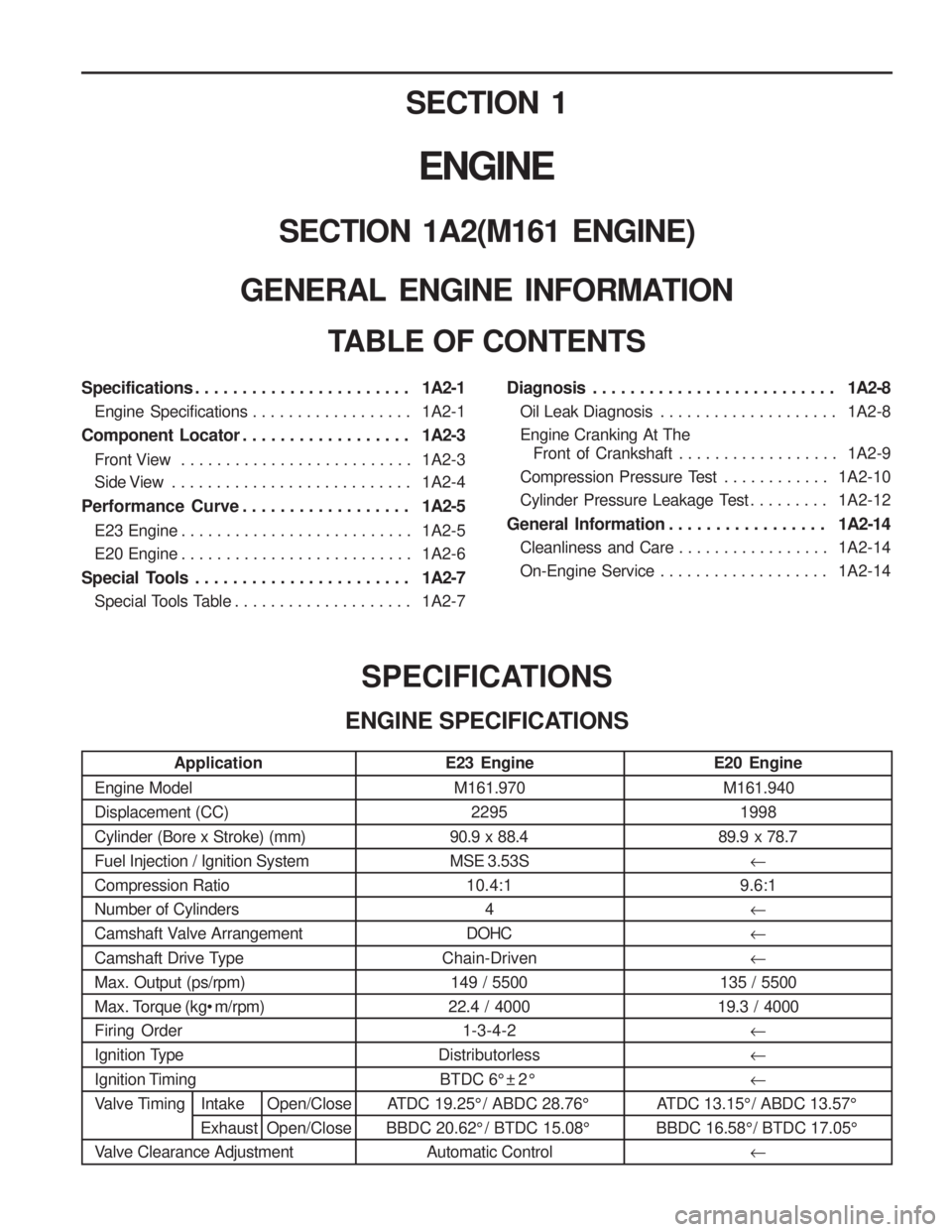
E20 Engine
M161.940 1998
89.9 x 78.7
�
9.6:1
� � �
135 / 5500
19.3 / 4000 � � �
ATDC 13.15° / ABDC 13.57°
BBDC 16.58° / BTDC 17.05° �
Application
Engine Model Displacement (CC) Cylinder (Bore x Stroke) (mm) Fuel Injection / Ignition SystemCompression RatioNumber of Cylinders
Camshaft Valve Arrangement
Camshaft Drive Type Max. Output (ps/rpm)
Max. Torque (kg m/rpm)Firing Order
Ignition Type
Ignition Timing
Valve Timing Intake Open/Close ExhaustOpen/Close
Valve Clearance Adjustment SPECIFICATIONS
ENGINE SPECIFICATIONS E23 EngineM161.970 2295
90.9 x 88.4
MSE 3.53S 10.4:1
4
DOHC
Chain-Driven 149 / 5500
22.4 / 4000 1-3-4-2
Distributorless
BTDC 6° ± 2 °
ATDC 19.25° / ABDC 28.76°
BBDC 20.62° / BTDC 15.08° Automatic Control
Page 34 of 1574
1A2-2 GENERAL ENGINE INFORMATION
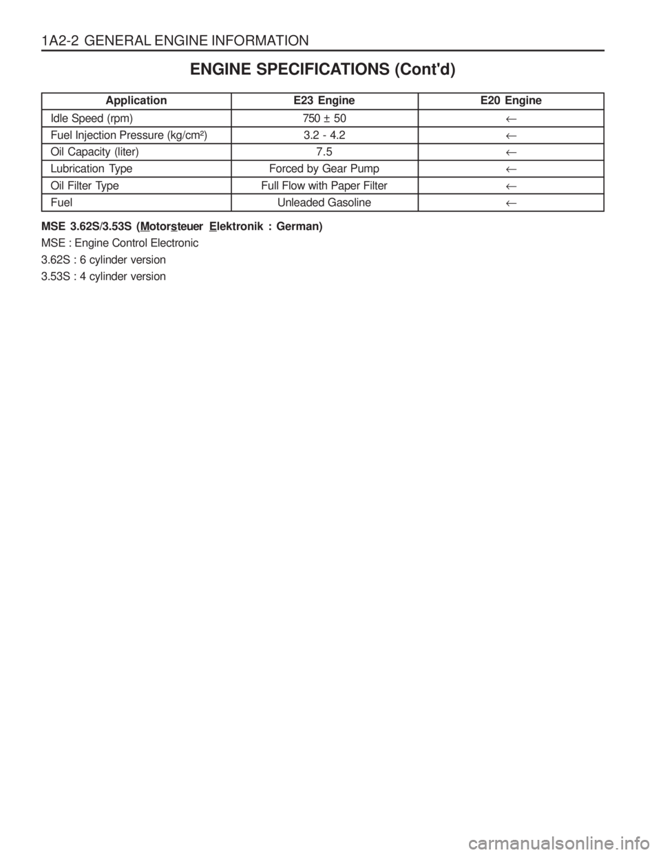
E20 Engine� ��� � �
Application
Idle Speed (rpm)
Fuel Injection Pressure (kg/cm²)Oil Capacity (liter)
Lubrication Type
Oil Filter Type Fuel ENGINE SPECIFICATIONS (Cont'd)
E23 Engine750 ± 503.2 - 4.2 7.5
Forced by Gear Pump
Full Flow with Paper Filter Unleaded Gasoline
MSE 3.62S/3.53S (Motors teuer Elektronik : German)
MSE : Engine Control Electronic 3.62S : 6 cylinder version3.53S : 4 cylinder version
Page 35 of 1574
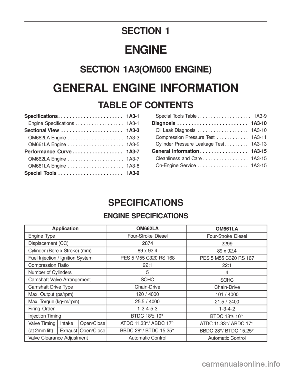
Application
Engine Type Displacement (CC) Cylinder (Bore x Stroke) (mm) Fuel Injection / Ignition SystemCompression RatioNumber of Cylinders
Camshaft Valve Arrangement
Camshaft Drive Type Max. Output (ps/rpm)
Max. Torque (kg• m/rpm)Firing Order
Injection Timing
Valve Timing Intake Open/Close
(at 2mm lift) Exhaust Open/Close
Valve Clearance Adjustment SECTION 1
ENGINE
SECTION 1A3(OM600 ENGINE)
GENERAL ENGINE INFORMATION
TABLE OF CONTENTS
Specifications . . . . . . . . . . . . . . . . . . . . . . . 1A3-1
Engine Specifications . . . . . . . . . . . . . . . . . . 1A3-1
Sectional View . . . . . . . . . . . . . . . . . . . . . . 1A3-3
OM662LA Engine . . . . . . . . . . . . . . . . . . . . . 1A3-3
OM661LA Engine . . . . . . . . . . . . . . . . . . . . . 1A3-5
Performance Curve . . . . . . . . . . . . . . . . . . 1A3-7
OM662LA Engine . . . . . . . . . . . . . . . . . . . . . 1A3-7
OM661LA Engine . . . . . . . . . . . . . . . . . . . . . 1A3-8
Special Tools . . . . . . . . . . . . . . . . . . . . . . . 1A3-9
SPECIFICATIONS
ENGINE SPECIFICATIONS
Special Tools Table . . . . . . . . . . . . . . . . . . . . 1A3-9
Diagnosis . . . . . . . . . . . . . . . . . . . . . . . . . 1A3-10
Oil Leak Diagnosis . . . . . . . . . . . . . . . . . . . 1A3-10
Compression Pressure Test . . . . . . . . . . . . 1A3-11
Cylinder Pressure Leakage Test . . . . . . . . . 1A3-13
General Information . . . . . . . . . . . . . . . . . 1A3-15
Cleanliness and Care . . . . . . . . . . . . . . . . . 1A3-15
On-Engine Service . . . . . . . . . . . . . . . . . . . 1A3-15
OM662LA
Four-Stroke Diesel 2874
89 x 92.4
PES 5 M55 C320 RS 168 22:15
SOHC
Chain-Drive 120 / 4000
25.5 / 4000 1-2-4-5-3
BTDC 18°± 10°
ATDC 11.33° / ABDC 17°
BBDC 28° / BTDC 15.25°
Automatic Control OM661LA
Four-Stroke Diesel 2299
89 x 92.4
PES 5 M55 C320 RS 167 22:1
4
SOHC
Chain-Drive 101 / 4000
21.5 / 2400 1-3-4-2
BTDC 18°± 10°
ATDC 11.33° / ABDC 17°
BBDC 28° / BTDC 15.25° Automatic Control
Page 36 of 1574
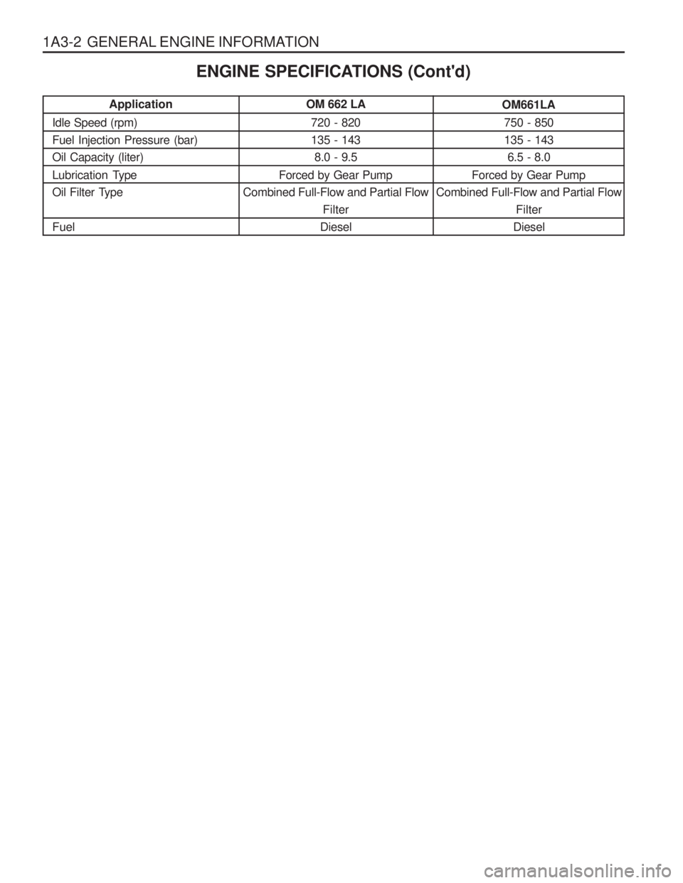
1A3-2 GENERAL ENGINE INFORMATION
OM 662 LA720 - 820 135 - 1438.0 - 9.5
Forced by Gear Pump
Combined Full-Flow and Partial Flow Filter
Diesel
Application
Idle Speed (rpm)Fuel Injection Pressure (bar)Oil Capacity (liter)
Lubrication Type
Oil Filter Type Fuel ENGINE SPECIFICATIONS (Cont'd)OM661LA
750 - 850 135 - 143 6.5 - 8.0
Forced by Gear Pump
Combined Full-Flow and Partial Flow
Filter
Diesel
Page 37 of 1574
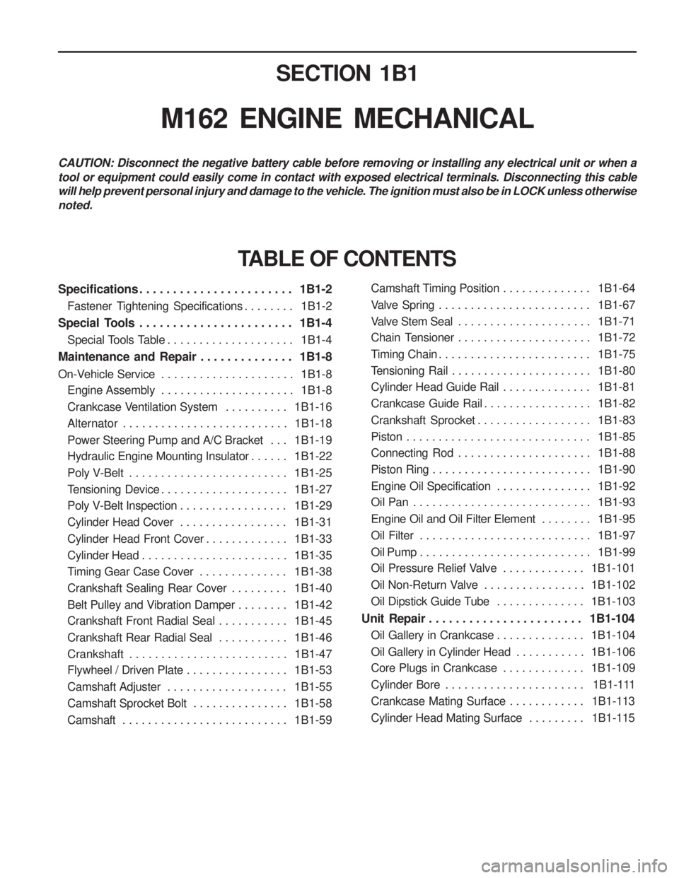
SECTION 1B1
M162 ENGINE MECHANICAL
CAUTION: Disconnect the negative battery cable before removing or installing any electrical unit or when a tool or equipment could easily come in contact with exposed electrical terminals. Disconnecting this cable will help prevent personal injury and damage to the vehicle. The ignition must also be in LOCK unless otherwisenoted.
Specifications . . . . . . . . . . . . . . . . . . . . . . . 1B1-2Fastener Tightening Specifications . . . . . . . . 1B1-2
Special Tools . . . . . . . . . . . . . . . . . . . . . . . 1B1-4 Special Tools Table . . . . . . . . . . . . . . . . . . . . 1B1-4
Maintenance and Repair . . . . . . . . . . . . . . 1B1-8
On-Vehicle Service . . . . . . . . . . . . . . . . . . . . . 1B1-8
Engine Assembly . . . . . . . . . . . . . . . . . . . . . 1B1-8
Crankcase Ventilation System . . . . . . . . . . 1B1-16
Alternator . . . . . . . . . . . . . . . . . . . . . . . . . . 1B1-18
Power Steering Pump and A/C Bracket . . . 1B1-19
Hydraulic Engine Mounting Insulator . . . . . . 1B1-22
Poly V-Belt . . . . . . . . . . . . . . . . . . . . . . . . . 1B1-25
Tensioning Device . . . . . . . . . . . . . . . . . . . . 1B1-27
Poly V-Belt Inspection . . . . . . . . . . . . . . . . . 1B1-29
Cylinder Head Cover . . . . . . . . . . . . . . . . . 1B1-31
Cylinder Head Front Cover . . . . . . . . . . . . . 1B1-33
Cylinder Head . . . . . . . . . . . . . . . . . . . . . . . 1B1-35
Timing Gear Case Cover . . . . . . . . . . . . . . 1B1-38
Crankshaft Sealing Rear Cover . . . . . . . . . 1B1-40
Belt Pulley and Vibration Damper . . . . . . . . 1B1-42
Crankshaft Front Radial Seal . . . . . . . . . . . 1B1-45
Crankshaft Rear Radial Seal . . . . . . . . . . . 1B1-46
Crankshaft . . . . . . . . . . . . . . . . . . . . . . . . . 1B1-47
Flywheel / Driven Plate . . . . . . . . . . . . . . . . 1B1-53
Camshaft Adjuster . . . . . . . . . . . . . . . . . . . 1B1-55
Camshaft Sprocket Bolt . . . . . . . . . . . . . . . 1B1-58
Camshaft . . . . . . . . . . . . . . . . . . . . . . . . . . 1B1-59
TABLE OF CONTENTS
Camshaft Timing Position . . . . . . . . . . . . . . 1B1-64
Valve Spring . . . . . . . . . . . . . . . . . . . . . . . . 1B1-67
Valve Stem Seal . . . . . . . . . . . . . . . . . . . . . 1B1-71
Chain Tensioner . . . . . . . . . . . . . . . . . . . . . 1B1-72
Timing Chain . . . . . . . . . . . . . . . . . . . . . . . . 1B1-75
Tensioning Rail . . . . . . . . . . . . . . . . . . . . . . 1B1-80
Cylinder Head Guide Rail . . . . . . . . . . . . . . 1B1-81
Crankcase Guide Rail . . . . . . . . . . . . . . . . . 1B1-82
Crankshaft Sprocket . . . . . . . . . . . . . . . . . . 1B1-83
Piston . . . . . . . . . . . . . . . . . . . . . . . . . . . . . 1B1-85
Connecting Rod . . . . . . . . . . . . . . . . . . . . . 1B1-88
Piston Ring . . . . . . . . . . . . . . . . . . . . . . . . . 1B1-90
Engine Oil Specification . . . . . . . . . . . . . . . 1B1-92
Oil Pan . . . . . . . . . . . . . . . . . . . . . . . . . . . . 1B1-93
Engine Oil and Oil Filter Element . . . . . . . . 1B1-95
Oil Filter . . . . . . . . . . . . . . . . . . . . . . . . . . . 1B1-97
Oil Pump . . . . . . . . . . . . . . . . . . . . . . . . . . . 1B1-99
Oil Pressure Relief Valve . . . . . . . . . . . . . 1B1-101
Oil Non-Return Valve . . . . . . . . . . . . . . . . 1B1-102
Oil Dipstick Guide Tube . . . . . . . . . . . . . . 1B1-103
Unit Repair . . . . . . . . . . . . . . . . . . . . . . . 1B1-104 Oil Gallery in Crankcase . . . . . . . . . . . . . . 1B1-104
Oil Gallery in Cylinder Head . . . . . . . . . . . 1B1-106
Core Plugs in Crankcase . . . . . . . . . . . . . 1B1-109
Cylinder Bore . . . . . . . . . . . . . . . . . . . . . . 1B1-111
Crankcase Mating Surface . . . . . . . . . . . . 1B1-113
Cylinder Head Mating Surface . . . . . . . . . 1B1-115