heating SSANGYONG MUSSO 2003 Owner's Manual
[x] Cancel search | Manufacturer: SSANGYONG, Model Year: 2003, Model line: MUSSO, Model: SSANGYONG MUSSO 2003Pages: 1574, PDF Size: 26.41 MB
Page 1189 of 1574

SUPPLEMENTAL RESTRAINT SYSTEM(SRS) 8B-9
Diagnosis Air bag control unit diagnoses each function in the intervals of 250ms - 20 sec. during start-up or driving to prevent unwanted air bag deployment. If there is defect, it turns on or blinks warning lamp to indicate defects in the air bag
system to the driver. And fatal defect is found, air bag control unit enters overall or partial shutdown status and fault code will be stored. Air bag control unit diagnoses following items.- Ignition TR - Acceleration
- Microprocessor, RAM and ROM
- Watchdog - Shutdown Switch
Diagnosis Condition Diagnosis ItemsStart-up (ignition ON)
During Driving
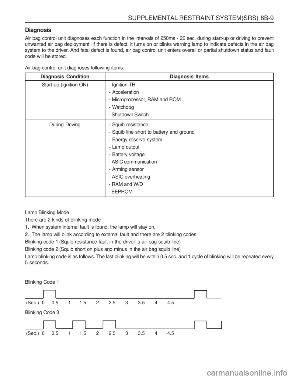
Lamp Blinking Mode There are 2 kinds of blinking mode
1. When system internal fault is found, the lamp will stay on.
2. The lamp will blink according to external fault and there are 2 blinking codes.
Blinking code 1 (Squib resistance fault in the driver’ s air bag squib line)
Blinking code 2 (Squib short on plus and minus in the air bag squib line)Lamp blinking code is as follows. The last blinking will be within 0.5 sec. and 1 cycle of blinking will be repeated every 5 seconds.
Blinking Code 1
(Sec.) 0 0.5 1 1.5 2 2.5 3 3.5 4 4.5
Blinking Code 3
(Sec.) 0 0.5 1 1.5 2 2.5 3 3.5 4 4.5 - Squib resistance - Squib line short to battery and ground - Energy reserve system - Lamp output- Battery voltage- ASIC communication- Arming sensor - ASIC overheating - RAM and W/D- EEPROM
Page 1213 of 1574

BODY WIRING SYSTEM 9A-11
ENGINE ROOM1 Engine Room Relay Box
1.1 Main Wiring Connector
1.2 Main Wiring Connector
1.3 Main Wiring Connector ........................................Gasoline E/G
1.4 Joint
1.5 Compressor, Condenser Fan Relay .....................Diesel E/G
1.6 Condenser Fan Relay 2
1.7 Air Conditioner Relay
1.8 Resistor with Diode .............................................. Gasoline E/G
1.9 Front Fog Lamp Relay
1.10 Condenser Fan Relay 1
1.11 Tail Lamp Relay
1.12 Horn Relay
2 Octane Selector ................................................... Gasoline E/G with HFM
3 Preheating Unit .................................................... Diesel E/G
4 Preheating Timer Unit .......................................... Diesel E/G
5 ECS Main Wiring Connector ................................ ECS
6 Brake Leveling Fluid Sensor
7 ABD Main Wiring Connector ................................ABD 5.0
7 - 1 ABS Main Wiring Connector ................................ABD 5.0
8 ABD main Wiring Connector ................................ABD 5.0
9 Engine Temperature Sensor ................................Diesel E/G
10 ABS 5.0 ECU ....................................................... ABS 5.0
10-1 ABD 5.0 Modulator ............................................... ABD 5.0
11 Front Washer Motor ............................................. Diesel E/G
12 Head Lamp Relay
13 Compressor ......................................................... Air Conditioner
14 Wheel Speed Sensor ........................................... ABS 5.0 or ABD 5.0
Page 1224 of 1574

9A-22 BODY WIRING SYSTEM
DIESEL ENGINE1 Preheating Unit
2 Main Wiring Connector
3 Glow Plug 1
4 Glow Plug 2 5 Glow Plug 3
6 Glow Plug 4
7 Glow Plug 5
8 Water Temperature Sensor (Gauge)
Page 1252 of 1574

INSTRUMENTATION/DRIVER INFORMATION 9E-3
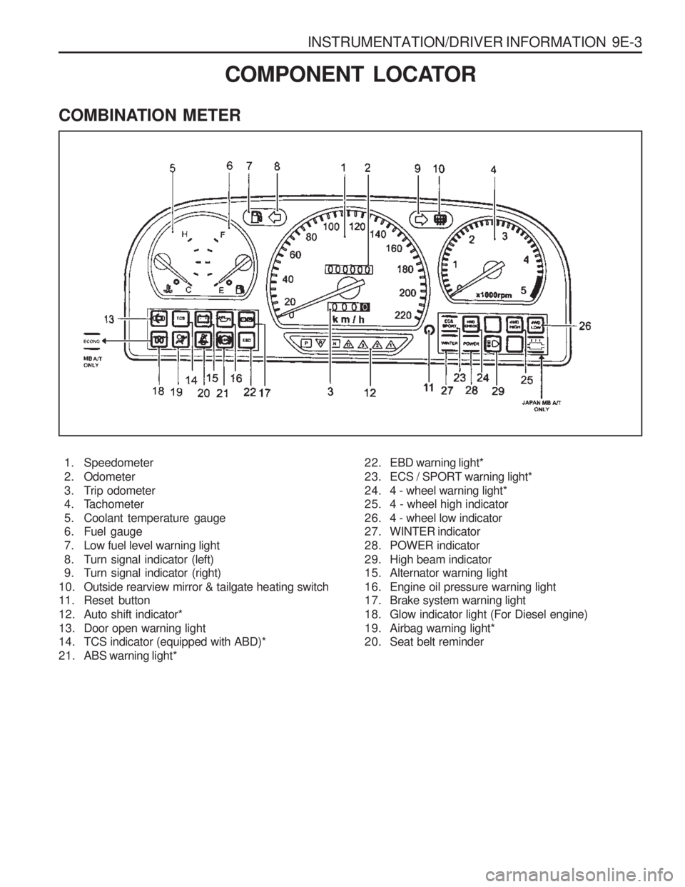
COMBINATION METER
COMPONENT LOCATOR
1. Speedometer
2. Odometer
3. Trip odometer
4. Tachometer
5. Coolant temperature gauge
6. Fuel gauge
7. Low fuel level warning light
8. Turn signal indicator (left)
9. Turn signal indicator (right)
10. Outside rearview mirror & tailgate heating switch
11. Reset button
12. Auto shift indicator*
13. Door open warning light
14. TCS indicator (equipped with ABD)*
21. ABS warning light* 22. EBD warning light*
23. ECS / SPORT warning light*
24. 4 - wheel warning light*
25. 4 - wheel high indicator
26. 4 - wheel low indicator
27. WINTER indicator
28. POWER indicator
29. High beam indicator
15. Alternator warning light
16. Engine oil pressure warning light
17. Brake system warning light
18. Glow indicator light (For Diesel engine)
19. Airbag warning light*
20. Seat belt reminder
Page 1275 of 1574

GLASS AND MIRRORS 9L-9
TAILGATE GLASS
1 Wiper Arm and Blade Assembly
2 Heating Lines3 Tailgate Trim
4 Tailgate Glass
Notice Removal and installation is as shown in upper drawings.
Page 1347 of 1574

MUSSO-SPORTS 1A-35
SUPPLEMENT
Main - Engine Engine - Engine Genertor - EngineMain - T/M Main - T/M MainMain
C103 (2Pin, White) C105 (8Pin, Black) C108 (16Pin, Black)C901 (16Pin, Black) C902 (12Pin, Black) S201 (Black)G204
b. CONNECTOR IDENTIFICATION SYMBOL & PIN NUMBER POSITION
a. CONNECTOR INFORMATION
C902
W/H T/M
C101
W/H MAIN C102
W/H MAIN C108
W/H ENGINE
CONNECTOR(NUMBER) CONNECTING. WIRING HARNESSCONNECTOR POSITION
Inside The Engine Room Fuse Block
Beside Pre-Heating Unit (DSL):MUSSO SPORT
Under The Air Cleaner Housing (DSL, N/Turbo) Upper The T/C(M/T)Upper The T/C(A/T) Behind The Cluster Upper The Huber EGR
1
2
1234
5678
1234 5678
9 101112
13 14 15 16
1234 5678
9 101112
13 14 15 16
C901
W/H T/M
1234
5678
9101112
HUBER EGR
CONTROL UNIT
24
43
23
42
22
41
21
40
20
39
19
38
18
37
17
36
16
35
15
34
14
33
13
32
12
31
11
30
10
29
9
28
8
27
7
26
6
25
62
81
61
80
60
79
59
78
58
77
57
76
56
75
55
74
54
73
53
72
52
71
51
70
50
69
49
68
48
67
47
66
46
65
45
64
12 45 3
44
63
Page 1353 of 1574

POSITION OF CONNECTORS AND GROUNDS 2-3
C361 C371C381C401C402C403 22
88626 White
ColorlessColorlessColorlessColorlessColorless Main - Co-Driver DoorFloor - Rear Left DoorFloor - Rear Right DoorFloor - Tail GateFloor - Tail GateFloor - Tail Gate
Inside Co-Driver Side Cowl PanelCenter 'B' PillarCenter Left 'B' PillarBehind The Left LampBehind The Left LampBehind The Left Lamp
2. CONNECTOR, GROUND AND SPLICE PACK INFORMATION
1) CONNECTOR
Connector
Number Connecting Wiring HarnessConnector PositionColorPin
Number
C101 C102C103C104C105C106C107 C108 C109C110C111C112C201C203C204C205 C206
C206B C207 C208C208
C208B C209C210C211C212 C213 C251C301C302C303 C304 C305 C351212 2
15 143 2
16 6
40 6 84
10 33
4 [6]
1616121584
1417 6 3
20 1614 12 6
22 Colorless Colorless
WhiteBlackBlackBlackBlack Black BlackBlackBlack Gray
White
Colorless WhiteBlackBlack Black BlackBlackBlackBlackBlackBlackBlack
White
Colorless Black
White WhiteWhite
Colorless White
Blue Main - Engine Main - EngineMain - EngineEngine - MainEngine - EngineGenerator - EngineGenerator - Engine Genertor - Engine Engine - MainMain - Engine MainEngine Main - ECM MainEngine Main - ECM MainMain - RoofMain Air BagMain - Driver SeatMain - T/MMain - Fuel Tank Main - Fuel Tank Main - T/MMain - T/MMain - T/MMain - T/MMain - T/MMain - T/MDLC Connector - MainMain - Air ConMain - ECM Main Driver Seat - Driver Seat, AUX Main - FloorMain - Floor Main - Floor Main - FloorMain - Floor Main - Driver DoorInside The Engine Room Fuse Block Inside The Engine Room Fuse BlockInside The Engine Room Fuse BlockUnder The Engine Room Fuse BlockBeside Pre-Heating Unit (DSL)Under The Air Cleaner Housing (DSL, Turbo)Under The Air Cleaner Housing (DSL, N/Turbo) Under The Air Cleaner Housing (GSL) Under The Coolant Reservoir TankBehind The ABS Module (HFM)Center The Engine Room Dash PanelCenter The Engine Room Dash PanelUpper The I/P Fuse BlockLeft The AudioUnder The Driver SeatUpper The T/C MotorUpper The T/C (DSL) Upper The T/C (GSL) Upper The T/CUpper The T/C (GSL)Upper The T/C (DSL)Upper The T/C (GSL)Upper The T/C (DSL)Upper The T/C (GSL)Beside The Steering ColumnBehind The Glove BoxBeside The ECM (MSE) Under The Driver Seat Beside The I/P Relay BlockBeside The I/P Relay BlockBeside The I/P Relay Block Inside Co-Driver Side Cowl Panel Beside Center ConsoleUpper The I/P Fuse Block
Connector
Number Connecting Wiring HarnessConnector PositionColorPin
Number
2) GROUND
G101 G102 G103G201 G202 G203G204G205 G206 G207G208 G209 G301G302G303 Ground Position
Wiring Harness
Ground
Number
Behind The Left LampBeside The Start Motor Behind The Right Head Lamp Right The I/P Fuse BlockBeside The STICSUpper The ECM Behind The Ashtray Beside The TCCUBeside The ABS Module Beside THe ECM Under THe CO-Driver SeatBeside The EBCMCenter The Left 'B' Pillar Beside The Left Rear Speaker Beside The Right Rear Speaker
Engine Engine Engine
Main MainMain Main MainMain Main MainMain
Floor Floor Floor
* [ ] : EURO III
Page 1366 of 1574

4-2 USAGE AND CAPACITY OF FUSES IN FUSE BOX
60A 80A 80A30A30A40A40A60A60A10A10A15A15A15A15A10A10A30A
Ef1Ef2Ef3Ef4Ef5Ef6Ef7Ef8Ef9
Ef10Ef11Ef12Ef13Ef14Ef15Ef16Ef17Ef18
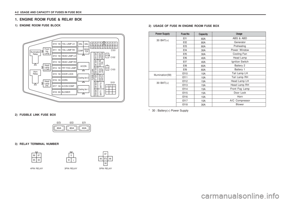
1. ENGINE ROOM FUSE & RELAY BOX
1) ENGINE ROOM FUSE BLOCK
2) USAGE OF FUSE IN ENGINE ROOM FUSE BOX
* 30 : Battery(+) Power Supply
Front
fog
Lamp
Head
Lamp
(LOW)
Head
Lamp (HI)
Illumination
Relay
Horn
Relay
A/CON C101
C102 C103 S101
Cooling fan-2
Cooling fan-1
Ef10 10ATAIL LAMP LH
Ef11 10ATAIL LAMP RH
Ef12 15AHEAD LAMP LH
Ef13 15AHEAD LAMP RH
Ef14 15AFRT FOG LAMP
Ef15 15ADOOR LOCK
Ef16 10AHORN
Ef17 10AA/CON COMP
Ef18 30ABLOWER
DSL GSL
COMP RESIS
TOR
109876 5432121 20 19 18 17 16 15 14 13 12 11
21
123
12
Ef9 60A
BATT1
Ef8 60ABATT2
Ef7 40AIGNITION SWITCH
Ef6 40A
FUSIBLE LINK
HEADLAMP
Ef5 30ACOOLING FAN
Ef4 30APOWER
WINDOW
2) FUSIBLE LINK FUSE BOX
80A 80A 60A
E
f3Ef2Ef1
3) RELAY TERMINAL NUMBER
8687
8530
S
BL8587a
30
87
86
4PIN RELAY 3PIN RELAY 5PIN RELAY ABS & ABD
Generator
Preheating
Power Window
Cooling FanHead Lamp
Ignition Switch Battery 2 Battery 1
Tail Lamp LH
Tail Lamp RH
Head Lamp LH
Head Lamp RH
Front Fog Lamp Door LockHorn
A/C Compressor
Blower
Fuse No Capacity UsagePower Supply
30 BAT(+)
Illumination(58)
30 BAT(+)
Page 1383 of 1574

5-16 ELECTRICAL WIRING DIAGRAMSMain - Engine Engine - Main Genertor - Engine EngineMain
C101 (21Pin, Colorless)C104 (15Pin, Black) C106 (4Pin, Black) G101 G201
b. CONNECTOR IDENTIFICATION SYMBOL & PIN NUMBER POSITION
a. CONNECTOR INFORMATION
C106
W/H GENERATOR
C101
W/H MAIN C104
W/H ENGINE PREHEATING
UNIT
CLUSTER
CONNECTOR(NUMBER) CONNECTING. WIRING HARNESSCONNECTOR POSITION
Inside The Engine Room Fuse Block Under The Engine Room Fuse Block Under The Air Cleaner Housing (DSL, Turbo)Behind The Left Lamp Right The I/P Fuse Block
12345 678910
11 12 13 14 15 16 17 18 19 20 21
1452
8
14
79
3
15131011
6
1212 341 2 35
46
11 2
29 38
28
13 2021
39 434842
2. PREHEAT'G UNIT CIRCUIT
30 15 BAT+IGN 1
31 GND
G101
* NA : Non Torbo
* LA : Torbo Intercooler F22
LB
BW
14 3 0
10A
Ef3 80A
12V Preheating Unit
SIG
SIG Starter
Motor
Relay "87"
Starter Motor
"ST"
B B5V 5V
CYL.1 CYL.2 CYL.3 Preheating PlugCYL.4 CYL.5
5V 5V 5V
G1 G2 G3 G4 G5
BL BW BR BY BG
5
B
6
G201
2
LA
T
31 50
15 BY
W
BY BY
C101
10
C106
LA
NA YL
RB RB
4
C104
6
Cluster (Preheat'gIndicationLamp)
ECT
Sensor 12
27
Page 1507 of 1574

5-142 ELECTRICAL WIRING DIAGRAMS
30. CLUSTER
1) SPEED METER, TACHO METER, TEMP GAUGE, FUEL GAUGE CIRCUITC104
W/H ENGINE
Engine - Main Engine - EngineGenerator - EngineGenerator - Engine Engine Main - ECM Main Main - Fuel TankMain - Fuel TankEnginex - MainMain - ECM Main Main - Floor MainMainMain
C104 (15Pin, Black)C105 (1Pin, Black)C106 (4Pin, Black)C107 (3Pin, Black) C111 (40Pin, Black) C206 (3Pin, Black)C206B (4Pin, Black)C212 (17Pin, White)C213 (6Pin, Colorless) C303 (14Pin, White) S201 (Black)G201G205
b. CONNECTOR IDENTIFICATION SYMBOL & PIN NUMBER POSITION
a. CONNECTOR INFORMATION
CONNECTOR(NUMBER)
CONNECTING. WIRING HARNESSCONNECTOR POSITION
Under The Engine Room Fuse Block Beside Pre-Heating Unit (DSL) Under The Air Cleaner Housing (DSL, Turbo)Under The Air Cleaner Housing (DSL, N/Turbo)Center The Engine Room Dash PanelUpper The T/C (DSL) Upper The T/C (GSL) Under The Coolant Reservoir TankBeside The ECM (MSE)Beside The I/P Relay BlockBehind The Cluster Right The I/P Fuse Block Beside The TCCU
C109
W/H ENGINEC212
W/H MAIN
12345 678910
11 12 13 14 15 16 17
C206
W/H MAIN C206B
(GSL)
W/H MAIN
C213
W/H ECM MAIN C107
W/H
GENERATOR (DSL) (GSL)
C106
W/H
GENERATOR
10 1
20 11
30 21
40 3112312 34
321
654
123
C303
W/H MAIN
12 45
78 3
9 101112 13 6
14
C111
W/H ECM MAIN
12 34
1
13
37
36
60
23456789101112
61
73
97
96
120
62 63 64 65 66 67 68 69 70 71 72
ECM (MSE)
112
29 38
28
13 2021
39 43484210987654321
20 19 18 17 16 15 14 13 12 11
28 27 26 25 24 23 22 21
36 35 34 33 32 31 30 29
STICS
CLUSTER
G205
"W"(GSL)
"P"(DSL)
Generator
Chime
Bell
"1" Stics
"11"
F24 10AF22 ( ) : DSL
[ ] : GSL(MSE)
Fuel
Low
WarningLamp
FuelGauge
10A
1
3
2
LY 17 19 29 27
15
14
RY W
W
3
RL GY 60
59 RL RL
Engine Coolant
TempSensor FuelSenderUnit
NA
LA
B 1
7
S201
BrWYY LB
Y
16 18 Cluster
VSS
Temp Gauge
Tachometer
SpeedMeterkm/h
TCM
"A19"
Stics "19"
ECS
"6"Stics"35"
G201 B G205
ECM (MSE)
RPM
CF
4C303
9
C109
3
C1071
C106
3 C104C206B C206
1 C105
GL
DSL
DSL
GSL
GSL
GL GL G G
B
DSL GSL
C213
36C111
6
33C206B
C206
DSL GSL
24
4(3) 1(2)
3(1)
1
C2061 C206B
15 IGN1
31 GND
[5]
[2]
[5] [2]
321
654
(GSL:EURO III)
FUEL SENDER UNIT
321
654
C206B
(GSL:EURO III) W/H MAIN