SSANGYONG MUSSO 2003 Owner's Manual
MUSSO 2003
SSANGYONG
SSANGYONG
https://www.carmanualsonline.info/img/67/57511/w960_57511-0.png
SSANGYONG MUSSO 2003 Owner's Manual
Page 213 of 1574
M161 ENGINE MECHANICAL 1B2-61
Removal & Installation Procedure
1. Unscrew the stretch bolt.Installation Notice
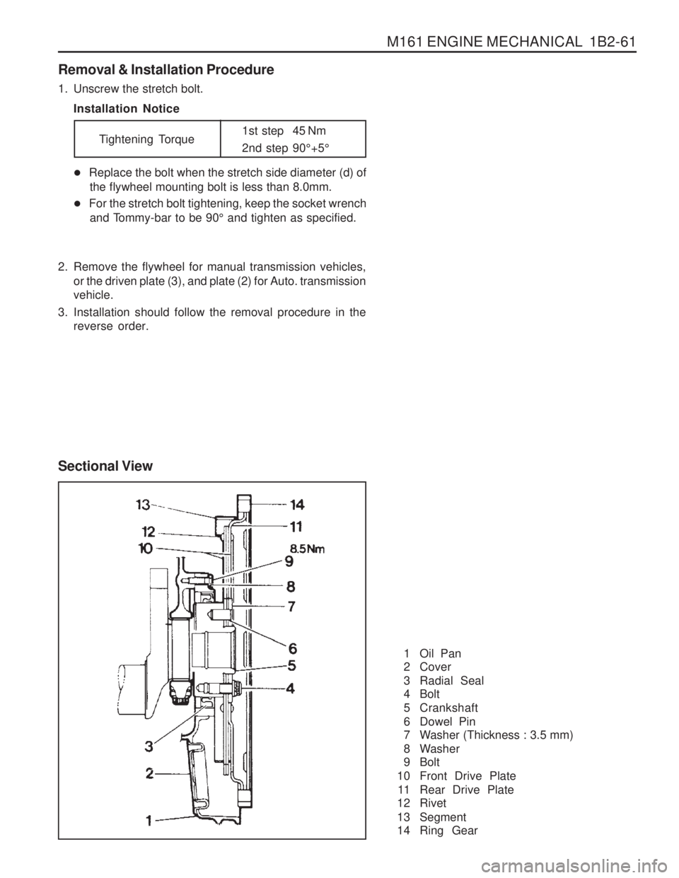
Sectional View
1 Oil Pan
2 Cover
3 Radial Seal
4 Bolt
5 Crankshaft
6 Dowel Pin
7 Washer (Thickness : 3.5 mm)
8 Washer
9 Bolt
10 Front Drive Plate 11 Rear Drive Plate
12 Rivet
13 Segment
14 Ring Gear
�
Replace the bolt when the stretch side diameter (d) of
the flywheel mounting bolt is less than 8.0mm.
� For the stretch bolt tightening, keep the socket wrench
and Tommy-bar to be 90 ° and tighten as specified.
2. Remove the flywheel for manual transmission vehicles, or the driven plate (3), and plate (2) for Auto. transmission vehicle.
3. Installation should follow the removal procedure in the reverse order. Tightening Torque
1st step 45 Nm
2nd step 90
°+5 °
Page 281 of 1574
1B3-16 OM600 ENGINE MECHANICAL
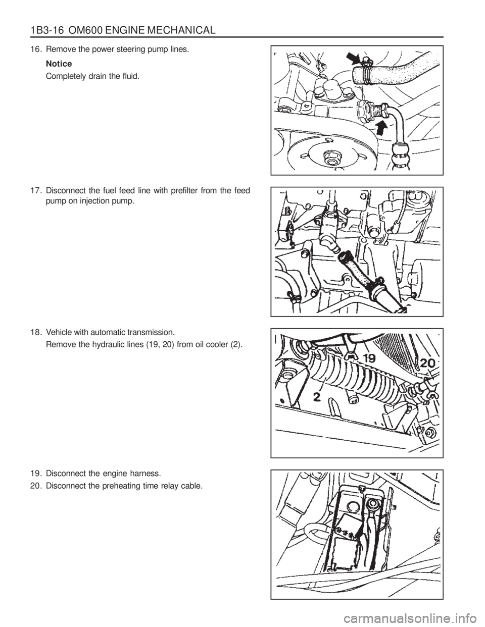
16. Remove the power steering pump lines.Notice Completely drain the fluid.
17. Disconnect the fuel feed line with prefilter from the feed pump on injection pump.
18. Vehicle with automatic transmission. Remove the hydraulic lines (19, 20) from oil cooler (2).
19. Disconnect the engine harness.
20. Disconnect the preheating time relay cable.
Page 283 of 1574
1B3-18 OM600 ENGINE MECHANICAL
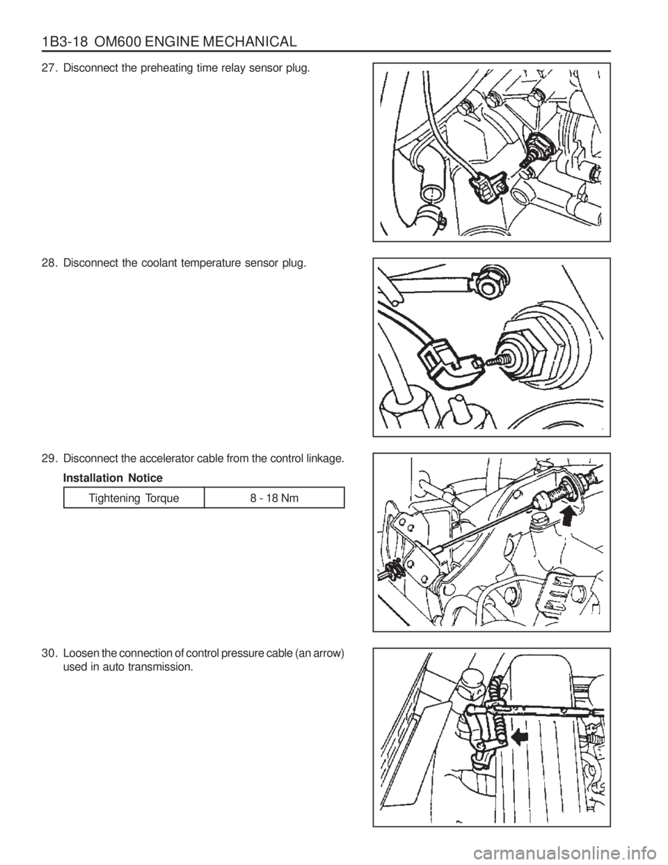
27. Disconnect the preheating time relay sensor plug.
28. Disconnect the coolant temperature sensor plug.
29. Disconnect the accelerator cable from the control linkage.Installation Notice
Tightening Torque 8 - 18 Nm
30. Loosen the connection of control pressure cable (an arrow) used in auto transmission.
Page 284 of 1574
OM600 ENGINE MECHANICAL 1B3-19
33. Disconnect the exhaust pipe flange from the exhaustmanifold. Installation Notice
35. Remove the shift control cable.
36. Remove the transmission.
Tightening TorqueAxle 70 ~ 80 Nm T/C 81 ~ 89 Nm
Tightening Torque 20 - 34 Nm
31. Separate the exhaust pipe flange from the turbo charger.
Installation Notice
32. Loosen the installing bolt of clutch release cylinder and remove the clutch release cylinder. Installation Notice
Tightening Torque 30 Nm
Tightening Torque 30 Nm
34. Remove the propeller shaft from the transmission. Installation Notice
Page 347 of 1574
1B3-82 OM600 ENGINE MECHANICAL
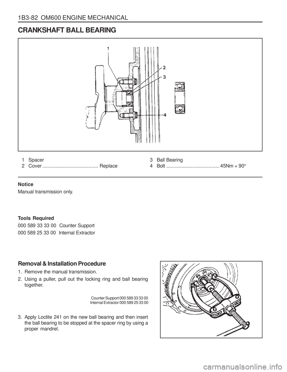
CRANKSHAFT BALL BEARING
1 Spacer
2 Cover ......................................... Replace
Notice
Manual transmission only.
Tools Required 000 589 33 33 00 Counter Support000 589 25 33 00 Internal Extractor Removal & Installation Procedure
1. Remove the manual transmission.
2. Using a puller, pull out the locking ring and ball bearing together.
Counter Support 000 589 33 33 00
Internal Extractor 000 589 25 33 00
3. Apply Loctite 241 on the new ball bearing and then insert the ball bearing to be stopped at the spacer ring by using a proper mandrel.3 Ball Bearing
4 Bolt ....................................... 45Nm + 90 °
Page 358 of 1574
OM600 ENGINE MECHANICAL 1B3-93
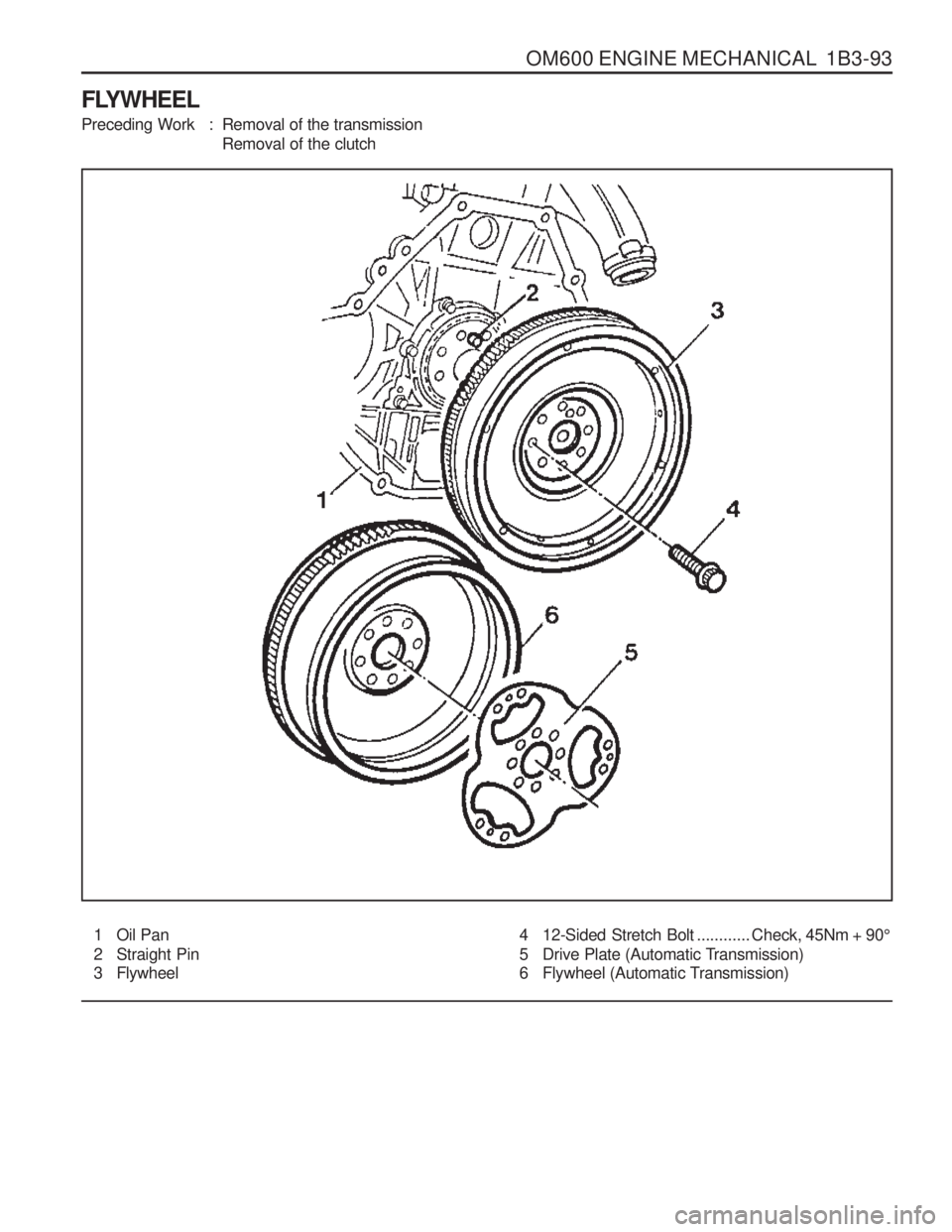
FLYWHEEL
Preceding Work : Removal of the transmissionRemoval of the clutch
1 Oil Pan
2 Straight Pin
3 Flywheel 4 12-Sided Stretch Bolt
............ Check, 45Nm + 90 °
5 Drive Plate (Automatic Transmission)
6 Flywheel (Automatic Transmission)
Page 359 of 1574
1B3-94 OM600 ENGINE MECHANICAL
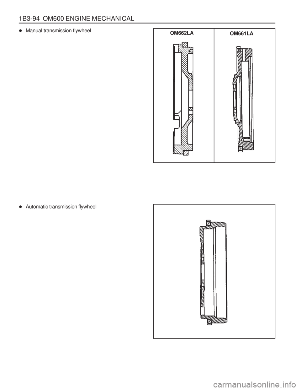
�Manual transmission flywheel
� Automatic transmission flywheel
OM661LA
OM662LA
Page 360 of 1574
OM600 ENGINE MECHANICAL 1B3-95
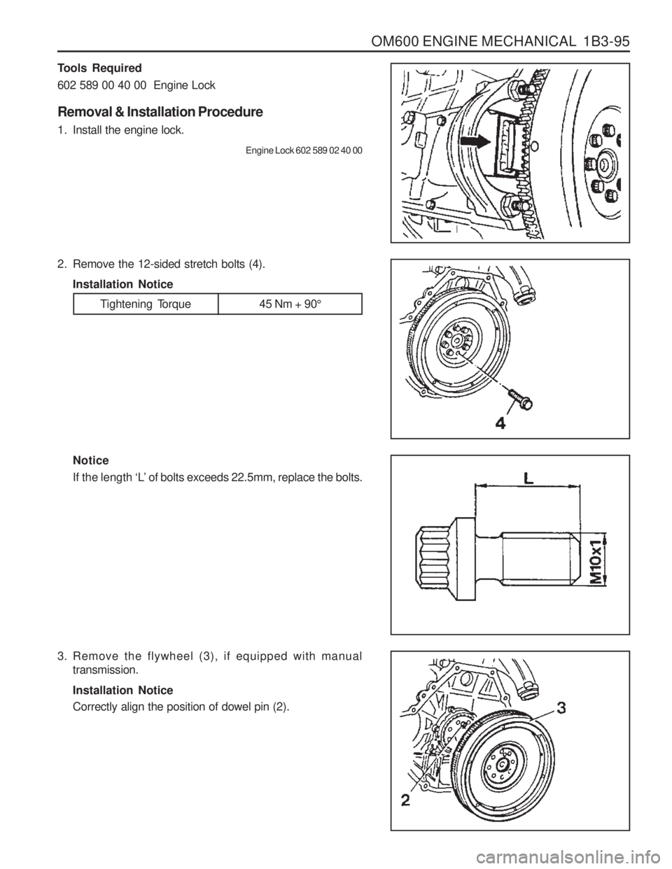
3. Remove the flywheel (3), if equipped with manualtransmission. Installation Notice Correctly align the position of dowel pin (2).
Tools Required 602 589 00 40 00 Engine Lock Removal & Installation Procedure
1. Install the engine lock.
Engine Lock 602 589 02 40 00
2. Remove the 12-sided stretch bolts (4). Installation Notice
Tightening Torque 45 Nm + 90 °
Notice If the length ‘L’ of bolts exceeds 22.5mm, replace the bolts.
Page 361 of 1574
1B3-96 OM600 ENGINE MECHANICAL
4. Remove the flywheel (6) and driven plate (5), if equippedwith automatic transmission. Installation Notice Correctly align the position of dowel pin (2).
5. Installation should follow the removal procedure in the reverse order.
Page 445 of 1574
OM600 ENGINE MECHANICAL 1B3-181
Tools Required 102 589 00 15 00 Drift 102 589 12 15 00 Drift Replacement Procedure
1. Completely drain the coolant.
2. Remove any parts which impede access.(Example : transmission, injection pump)
3. Place the screwdriver to the deepdrawn edge of the core plug and pull forward and then rotate 90 °.
4. Pull out the core plug with pliers.
5. Thoroughly clean the sealing surface and apply Loctite 241.
6. Install the new core plug by using a drift. Drift 102 589 00 15 00 (F34) Drift 102 589 12 15 00 (F17)
7. Install the removed parts and fill the coolant. Notice The adhesive must be allowed to harden for about 45 minutes before filling of coolant.
8. Warm up the engine and check the coolant for leaks.
