SSANGYONG MUSSO 2003 Service Manual
MUSSO 2003
SSANGYONG
SSANGYONG
https://www.carmanualsonline.info/img/67/57511/w960_57511-0.png
SSANGYONG MUSSO 2003 Service Manual
Trending: transmission fluid, brake, Body wiring, AUX, oil level, four wheel drive, checking oil
Page 331 of 1574
1B3-66 OM600 ENGINE MECHANICAL
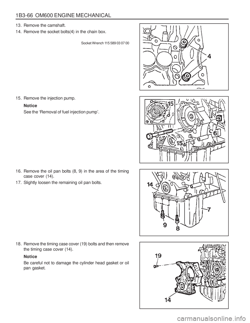
18. Remove the timing case cover (19) bolts and then removethe timing case cover (14). Notice Be careful not to damage the cylinder head gasket or oil pan gasket.
13. Remove the camshaft.
14. Remove the socket bolts(4) in the chain box.
Socket Wrench 115 589 03 07 00
15. Remove the injection pump. NoticeSee the ‘Removal of fuel injection pump ’.
16. Remove the oil pan bolts (8, 9) in the area of the timing case cover (14).
17. Slightly loosen the remaining oil pan bolts.
Page 332 of 1574
OM600 ENGINE MECHANICAL 1B3-67
Installation Procedure
1. Thoroughly clean the sealing surface and apply sealant.
2. Install the timing case cover.Notice Bolts arrangement
1.M6 x 60
2.M6 x 70
3.M6 x 40
3. Tighten the socket bolts in the chain box.
Tightening Torque 10 Nm
Tightening Torque 23 Nm
4. Tighten the oil pan bolts.
Tightening Torque 10 Nm 10 Nm23 Nm
Socket bolt
M6 bolt M8 bolt
Page 333 of 1574
1B3-68 OM600 ENGINE MECHANICAL
Tightening Torque25 Nm
5. Install the flange, vibration damper and crankshaft belt
pulley. Notice
Replace front radial seal if necessary.
6. Install the alternator bracket.
25 Nm
Front
Side
7. Install the alternator
Tightening TorqueUpper - 25 Nm Low - 25 Nm
8. Install the cylinder head cover.
Tightening Torque 10 Nm
9. Tighten the injection pump mounting bolts.
Tightening Torque 23 Nm
Page 334 of 1574
OM600 ENGINE MECHANICAL 1B3-69
10. Install the fuel filter.
11. Install the vacuum pump.
12. Install the power steering pump.
13. Install the power steering pump pulley.
Tightening Torque 25 Nm
Tightening Torque 10 Nm
Tightening Torque 23 Nm
Tightening Torque 32 Nm
14. Install the guide pulley bracket.
Tightening Torque 9 Nm
Page 335 of 1574
1B3-70 OM600 ENGINE MECHANICAL
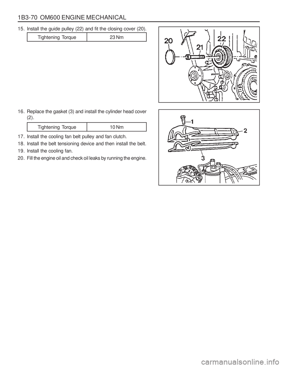
15. Install the guide pulley (22) and fit the closing cover (20).
16. Replace the gasket (3) and install the cylinder head cover(2).
17. Install the cooling fan belt pulley and fan clutch.
18. Install the belt tensioning device and then install the belt.
19. Install the cooling fan.
20. Fill the engine oil and check oil leaks by running the engine.
Tightening Torque 23 Nm
Tightening Torque 10 Nm
Page 336 of 1574
OM600 ENGINE MECHANICAL 1B3-71
CRANKSHAFT END COVER Preceding Work : Removal of flywheel and driven plate.
1 Crankshaft Flange
2 End Cover.............................. Clean, Loctite 573
3 Bolt ......................................... 10Nm, Loctite 5734 Radial Seal
............................................ Replace
5 Dowel Sleeve
6 Bolt ......................................... 10Nm, Loctite 573
Page 337 of 1574
1B3-72 OM600 ENGINE MECHANICAL
Tools Required 601 589 03 43 00 Oil Seal Assmbler Removal Procedure
1. Remove the bolts (3, 6) from end cover, By pulling out thelugs (arrow), remove the cover. Notice Be careful not to damage the oil pan gasket.
2. Remove the radial seal (4) with care not to damage the sealing surface.
Installation Procedure
1. Thoroughly clean the sealing surface of end cover and applyLoctite 573.
2. Clean the groove of radial seal.
3. Apply Loctite 573 on the bolts and install the end cover.
Tightening Torque 10 Nm
Notice Be careful not to damage the oil pan gasket.
4. Install the inner oil seal assembler to the crankshaft flange.
Oil Seal Assembler 601 589 03 43 00
Page 338 of 1574
OM600 ENGINE MECHANICAL 1B3-73
Notice The sealing lip of the repair radial seal is offset to the inside by 3mm to ensure that it does not run in any groove whichthe standard radial seal may have left on the crankshaftflange.
7. Install the outer oil seal assembler on he seal and by tightening the bolts, press the radial seal into the end coveras far as the stop. Notice The seal must be positioned exactly at right angles in the end cover to ensure that it provides a proper seal.
Oil Seal Assembler 601 589 03 43 00 A Standard Radial Seal
B Repair Radial Seal
5. Coat a little oil on the sealing lip of new radial seal and
contacting surface. Notice Don ’t use grease.
6. Insert the new radial seal (4) onto the oil seal assembler (7).
Page 339 of 1574
1B3-74 OM600 ENGINE MECHANICAL
VIBRATION DAMPER AND HUB
Preceding Work : Removal of the cooling fanRemoval of poly V-belt
1 Bolt............................................................ 10Nm
2 Cooling Fan Belt Pulley
3 Socket Bolt ................................................ 23Nm
4 Crankshaft Belt Pulley
5 Vibration Damper 6 Bolt
................................................ 200Nm + 90 °
7 Washer
8 Straight Pin
9 Hub
10 Oil Pan
Page 340 of 1574
OM600 ENGINE MECHANICAL 1B3-75
Sectional View
3 Socket Bolt
4 Crankshaft Belt Pulley
5 Vibration Damper
6 Bolt
7 Washer
8 Straight Pin
Notice The mounting position of vibration damper is fixed by straight pin (8).
Tools Required 602 589 00 40 00 Engine Lock103 589 00 30 00 Puller 9 Hub
11 Radial Seal
12 Timing Gear Case Cover
13 Key
14 Crankshaft Sprocket
16 Crankshaft
Trending: engine oil capacity, diagnostic menu, air condition, 4wd fuse, length, spark plugs, fuse box


