SSANGYONG MUSSO 2003 Service Manual
MUSSO 2003
SSANGYONG
SSANGYONG
https://www.carmanualsonline.info/img/67/57511/w960_57511-0.png
SSANGYONG MUSSO 2003 Service Manual
Trending: Transfer case, wipers, sunroof, radiator cap, light, brake sensor, coolant level
Page 371 of 1574
1B3-106 OM600 ENGINE MECHANICAL
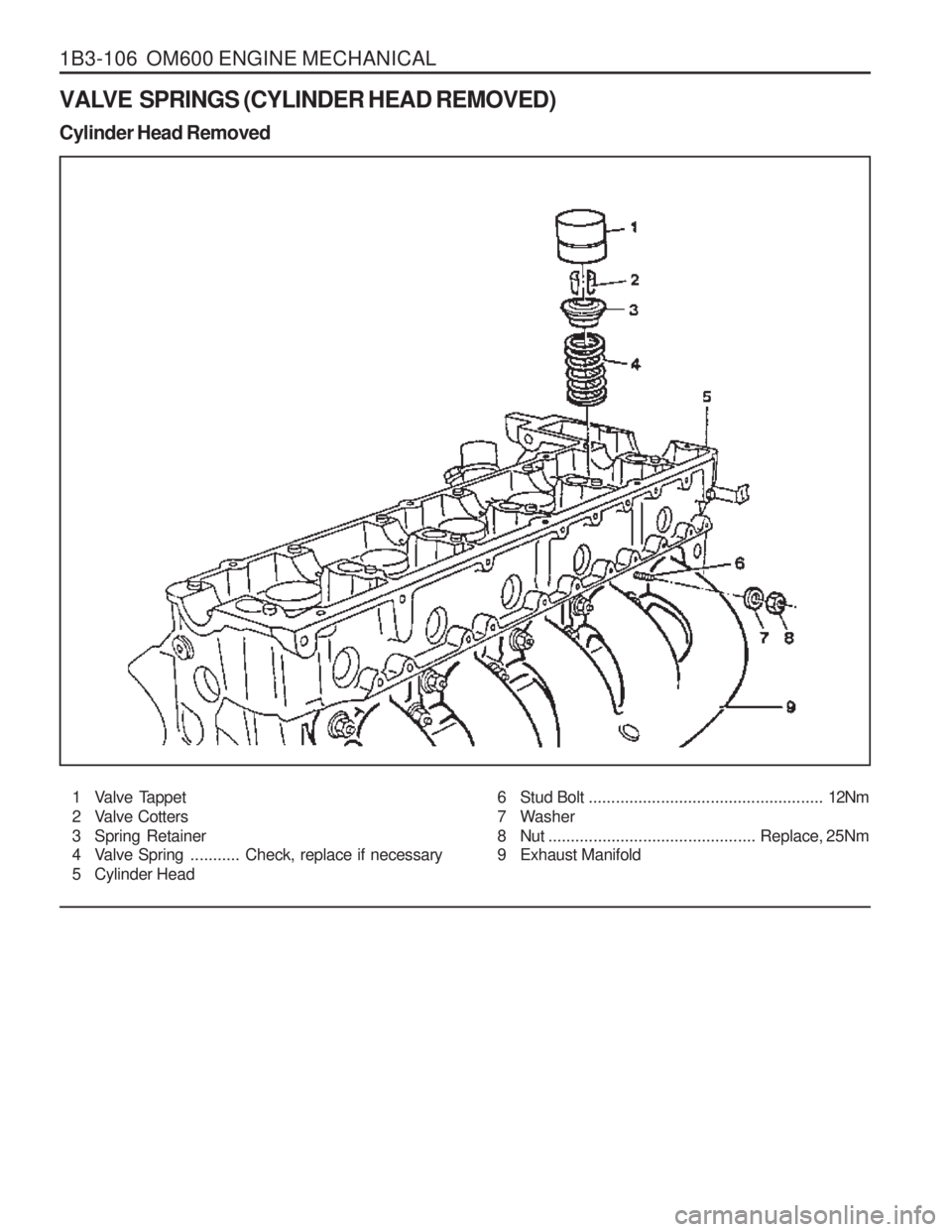
VALVE SPRINGS (CYLINDER HEAD REMOVED) Cylinder Head Removed1 Valve Tappet
2 Valve Cotters
3 Spring Retainer
4 Valve Spring ...........Check, replace if necessary
5 Cylinder Head
6 Stud Bolt .................................................... 12Nm
7 Washer
8 Nut .............................................. Replace, 25Nm
9 Exhaust Manifold
Page 372 of 1574
OM600 ENGINE MECHANICAL 1B3-107
Removal & Installation Procedure
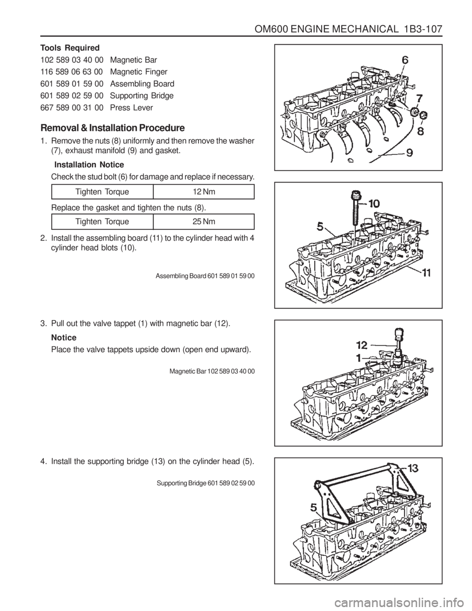
1. Remove the nuts (8) uniformly and then remove the washer(7), exhaust manifold (9) and gasket. Installation Notice
Check the stud bolt (6) for damage and replace if necessary.
Tighten Torque 12 Nm
Tighten Torque 25 Nm
Tools Required
102 589 03 40 00 Magnetic Bar
116 589 06 63 00 Magnetic Finger
601 589 01 59 00 Assembling Board
601 589 02 59 00 Supporting Bridge
667 589 00 31 00 Press Lever
Replace the gasket and tighten the nuts (8).
2. Install the assembling board (11) to the cylinder head with 4 cylinder head blots (10).
Assembling Board 601 589 01 59 00
3. Pull out the valve tappet (1) with magnetic bar (12). NoticePlace the valve tappets upside down (open end upward).
Magnetic Bar 102 589 03 40 00
4. Install the supporting bridge (13) on the cylinder head (5).Supporting Bridge 601 589 02 59 00
Page 373 of 1574
1B3-108 OM600 ENGINE MECHANICAL
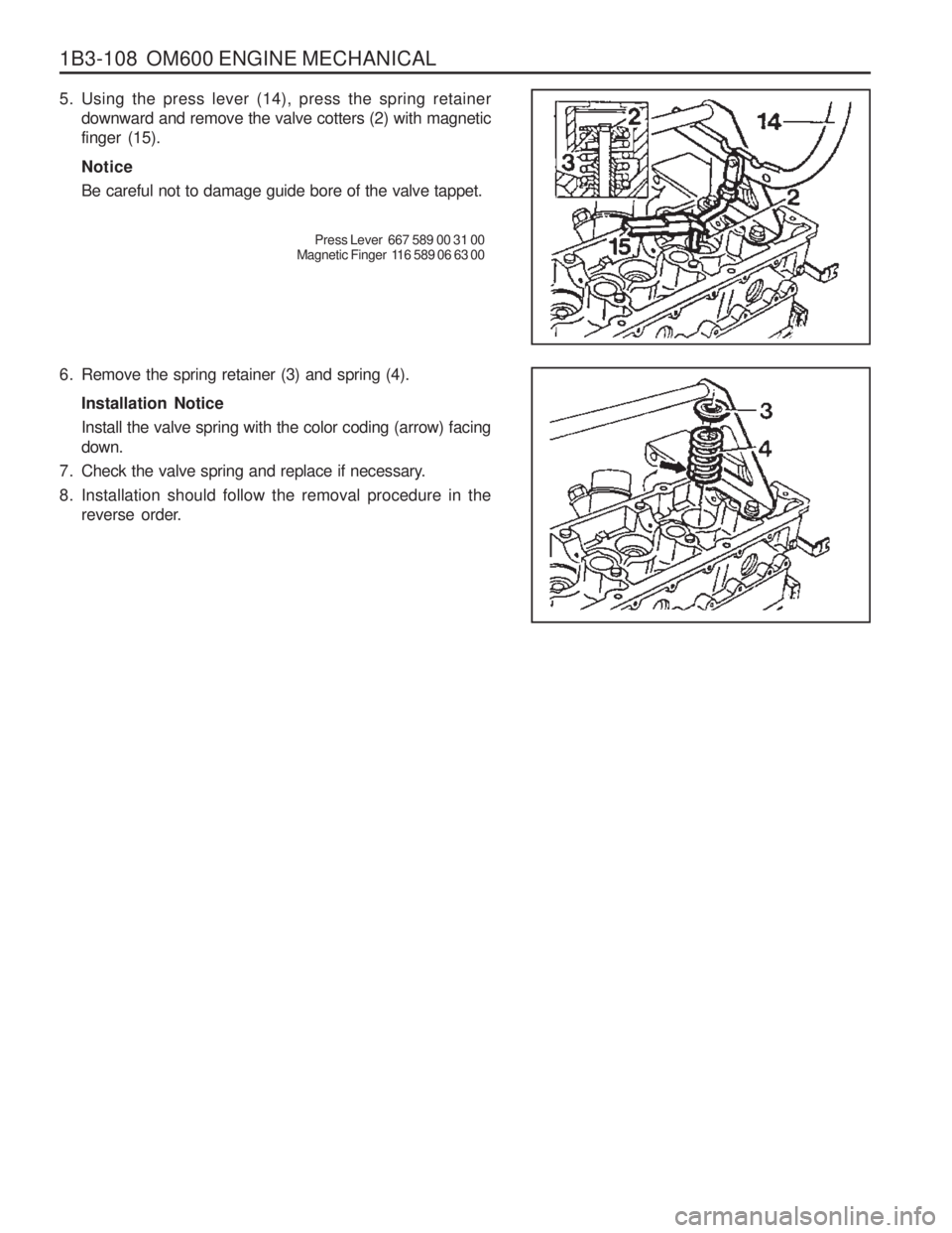
5. Using the press lever (14), press the spring retainerdownward and remove the valve cotters (2) with magnetic finger (15). Notice Be careful not to damage guide bore of the valve tappet.
Press Lever 667 589 00 31 00
Magnetic Finger 116 589 06 63 00
6. Remove the spring retainer (3) and spring (4). Installation NoticeInstall the valve spring with the color coding (arrow) facing down.
7. Check the valve spring and replace if necessary.
8. Installation should follow the removal procedure in the reverse order.
Page 374 of 1574
OM600 ENGINE MECHANICAL 1B3-109
VALVE SPRINGS (CYLINDER HEAD INSTALLED) Preceding Work : Removal of camshaft1 Valve Tappet
2 Valve Cotters
3 Spring Retainer 4 Valve Spring
.......... Check, replace if necessary
5 Timing Chain
6 Cylinder Head
Notice Remove the valve springs only when the piston is at TDC.
Tools Required 102 589 03 40 00 Magnetic Bar
116 589 06 63 00 Magnetic Finger603 589 01 40 00 Holding Wheel667 589 00 31 00 Press Lever667 589 02 63 00 Supporting Bar
Page 375 of 1574
1B3-110 OM600 ENGINE MECHANICAL
5. Using the press lever (9), press the spring retainer(3)downward and remove the valve cotters (2) with magnetic finger (10). Notice Be careful not to damage guide bore of the valve tappet.
Press Lever 667 589 00 31 00
Magnetic Finger 116 589 06 63 00
Removal & Installation Procedure
1. Remove the valve tappet (1) with magentic lifter.
Notice Place the valve tappets upside down (open end upward)
Magentic Liter 102 589 03 40 00
2. Install the holding wheel (7) into the timing chain of camshaft sprocket piston.
Holding Wheel 603 589 01 40 00
3. Position the piston of relevant cylinder at TDC.
4. Install the supporting bar (8). Supporting Bar 667 589 02 63 00
Page 376 of 1574
OM600 ENGINE MECHANICAL 1B3-111
6. Remove the spring retainer(3) and spring (4).
7. Check the valve spring and replace if necessary.
8. Insert valve spring (4) with the color coding (arrow) facingdown and insert valve spring Retainer(3).
9. By press the spring retainer(3) with press lever (90), install the valve cotters with magnetic finger (10).
Press Lever 667 589 00 31 00
Magnetic Finger 116 589 06 63 00
10. Remove the supporting bar.
11. Remove the holding wheel (7) from the timing chain (5). Holding Wheel 603 589 01 40 00
13. Coat the valve tappet with oil and install it. Magnetic Bar 102 589 03 40 00
Page 377 of 1574
1B3-112 OM600 ENGINE MECHANICAL
VALVE STEM SEALS Preceding Work : Removal of camshaft.
1 Valve Tappet
2 Valve Cotters
3 Spring Retainer4 Valve Spring
...........Check, replace if necessary
5 Valve Stem Seal
6 Valve
Notice Remove the valve stem seals when the piston is positioned at TDC.
Page 378 of 1574
OM600 ENGINE MECHANICAL 1B3-113
Tools Required 667 589 00 31 00 Press Lever104 589 00 37 00 Pliers102 589 03 40 00 Magnetic Lifter603 589 01 40 00 Holding Wheel601 589 02 43 00 Drift
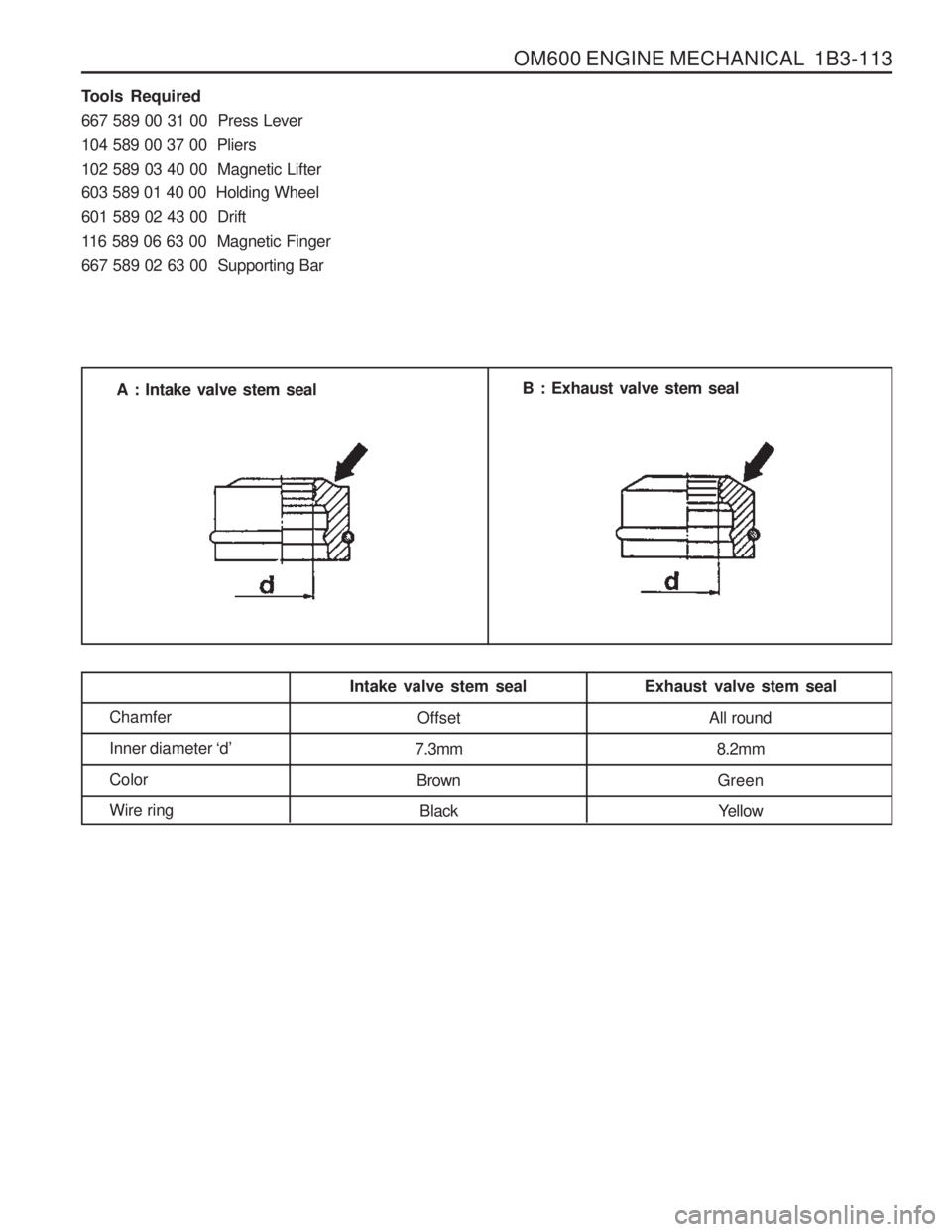
116 589 06 63 00 Magnetic Finger667 589 02 63 00 Supporting BarA : Intake valve stem seal
B : Exhaust valve stem seal
Chamfer Inner diameter ‘d’
ColorWire ring Intake valve stem seal
Offset
7.3mm Brown Black Exhaust valve stem seal
All round8.2mmGreen Yellow
Page 379 of 1574
1B3-114 OM600 ENGINE MECHANICAL Replacement Procedure
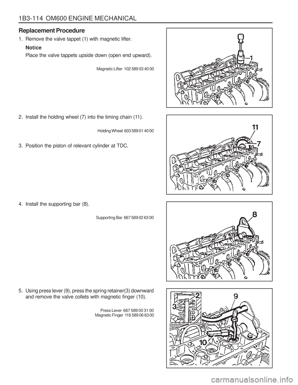
1. Remove the valve tappet (1) with magnetic lifter.Notice Place the valve tappets upside down (open end upward).
Magnetic Lifter 102 589 03 40 00
2. Install the holding wheel (7) into the timing chain (11). Holding Wheel 603 589 01 40 00
3. Position the piston of relevant cylinder at TDC.
4. Install the supporting bar (8). Supporting Bar 667 589 02 63 00
5. Using press lever (9), press the spring retainer(3) downward and remove the valve collets with magnetic finger (10).
Press Lever 667 589 00 31 00
Magnetic Finger 116 589 06 63 00
Page 380 of 1574
OM600 ENGINE MECHANICAL 1B3-115
6. Remove the spring retainer(3) and valve spring (4).
7. Remove the valve stem seal (5).Pliers 104 589 00 37 00
8. Insert the cap (12) onto the valve (6) and install the new valve stem seal (5) and then remover the cap.
Drift 601 589 02 43 00
9. By pressing the spring seat with press lever (9), install the valve cotters(2) with magnetic finger (10). Notice Be careful not to damage guide bore of the valve tappet.
Press Lever 667 589 00 31 00
Magnetic Finger 116 589 06 63 00
Trending: service indicator, battery location, manual transmission, check oil, fog light bulb, keyless, reset
