SSANGYONG MUSSO 2003 Service Manual
MUSSO 2003
SSANGYONG
SSANGYONG
https://www.carmanualsonline.info/img/67/57511/w960_57511-0.png
SSANGYONG MUSSO 2003 Service Manual
Trending: tyre pressure, checking oil, timing belt, transmission, adding oil, warning lights, hood release
Page 441 of 1574
OM600 ENGINE MECHANICAL 1B3-177
CYLINDER HEAD PRESSURE LEAKAGE TEST Preceding Work : Removal of the cylinder head Removal of the exhaust manifold Removal of the valve
1 Feed Pipe
2 Bolt
3 Return Connection
4 Gasket ................................................................ Replace
5 Coolant Gallery ................................................... Sealing
6 Pressure Measuring Plate ..................................Completely tight to the cylinder head
7 Cylinder Head .....................................................
Immerse with pressure measuring plate into warm water of approx. 60 °C and pressurize with compressed
airof 2 bar.
Notice If air bubbles are seen, replace the cylinderhead.
Tools Required
115 589 34 63 00 Pressure Measuring Plate 601 589 00 25 00 Suspension Device
UNIT REPAIR
Page 442 of 1574
1B3-178 OM600 ENGINE MECHANICALHeight ‘A’
(cylinder head surface - cylinder head cover surface) Minimum height after machiningPermissible unevenness of parting surface Permissible variation of parallelism (longitud. Direction) Peak-to-valley height
Valve arrears ‘a’
Prechamber protrusion
Service Data
In longitudinal direction In transverse direction Intake valve Exhaust valve
142.9 - 143.1mm
142.5mm0.08mm0.0mm
Max. 0.1mm
0.0017mm
0.1 - 0.7mm 0.1 - 0.7mm 7.6 - 8.1mm
FACING CYLINDER HEAD MATING SURFACE
Preceding Work : Removal of prechamber Cylinder head pressure leakage test
1 Valve
2 Cylinder Head
3 Prechamber
A Height of Cylinder Head B Longitudinal Direction
C Transverse Direction
a Valve Arrears
b Prechamber Protrusion
Page 443 of 1574
OM600 ENGINE MECHANICAL 1B3-179
Measurement Procedure
1. Measure height ‘A’ .
Limit 142.5 mm
Notice If the height is less than 142.5mm, replace the cylinder head.
2. Insert the valve (1) and measure valve arrears ‘a’.
Valve Arrears ‘a’ 0.1 - 0.7 mm
Notice If out of standard, machine the valve seat.
3. Install the prechamber and measure protrusion ‘C’.
Protrusion ‘C’ 7.6 - 8.1mm
4. Assemble the engine and check the valve timing.
Page 444 of 1574
1B3-180 OM600 ENGINE MECHANICAL
REPLACEMENT OF CRANKCASE CORE PLUG Left
Right
Core plug .......................................................
� 34mm
OM661LA - 2EA OM662LA - 3EA Core plug
.......................................................� 34mm
OM661LA - 2EAOM662LA - 3EA
Core plug .......................................................
� 17mm
OM661LA - 1EA OM662LA - 1EA Core plug
.......................................................� 34mm
OM661LA - 1EAOM662LA - 1EA
Left
Right
Page 445 of 1574
OM600 ENGINE MECHANICAL 1B3-181
Tools Required 102 589 00 15 00 Drift 102 589 12 15 00 Drift Replacement Procedure
1. Completely drain the coolant.
2. Remove any parts which impede access.(Example : transmission, injection pump)
3. Place the screwdriver to the deepdrawn edge of the core plug and pull forward and then rotate 90 °.
4. Pull out the core plug with pliers.
5. Thoroughly clean the sealing surface and apply Loctite 241.
6. Install the new core plug by using a drift. Drift 102 589 00 15 00 (F34) Drift 102 589 12 15 00 (F17)
7. Install the removed parts and fill the coolant. Notice The adhesive must be allowed to harden for about 45 minutes before filling of coolant.
8. Warm up the engine and check the coolant for leaks.
Page 446 of 1574
1B3-182 OM600 ENGINE MECHANICAL Service Data
Height ‘Y’
Permissible unevenness of contacting surface Permissible roughness upper contacting surface Permissible variation of parallelism of crankcase uppersurface to lower surface in longitudinal directionPiston protrusion at TDC to crankcase upper surface
In longitudinal direction (B) In transverse direction (C) Min. 299.62 mm
0.06 mm 0.06 mm
0.0006 - 0.0016 mm 0.05 mm
0.965 mm0.735 mm
Max. Min.
FACING CRANKCASE CONTACTING SURFACE
1 Crankcase
2 Crankcase Contacting Surface
Y Height (crankcase upper surface - crankcase lower surface) B Longitudinal Direction
C Transverse Direction H Chamfer Heightb Chamfer Angle
Page 447 of 1574
OM600 ENGINE MECHANICAL 1B3-183
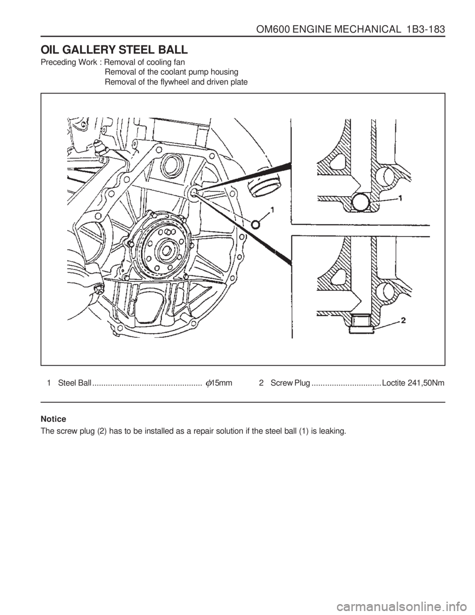
OIL GALLERY STEEL BALL Preceding Work : Removal of cooling fan Removal of the coolant pump housing Removal of the flywheel and driven plate
1 Steel Ball.................................................�15mm 2 Screw Plug ............................... Loctite 241,50Nm
Notice The screw plug (2) has to be installed as a repair solution if the steel ball (1) is leaking.
Page 448 of 1574
1B3-184 OM600 ENGINE MECHANICAL3 Steel Ball .................................................
�17mm
4 Seal5 Screw Plug ................................................. 50Nm
Notice The seal (4) and screw plug (5) have to be installed as a repair solution if the steel ball (3) is leaking.
Tools Required 601 589 08 15 00 Drift
Page 449 of 1574
OM600 ENGINE MECHANICAL 1B3-185
Removal & Installation Procedure
1. Remove the timing case cover.
2. By inserting a round bar (6) approx. 0.7m from the back tothe front side through the oil gallery, knock out the steel balls (1,3). Notice Be careful not to damage the bores of the steel balls.
6 Shop-made tool
3. Thoroughly clean the bores of steel balls.
4. Place the steel ball (3) onto the drift (7) with a little grease and position to the bore and then tap until the drift stops.
Drift 601 589 08 15 00
5. Place the steel ball (1) onto the drift (7) with a little grease and position to the bore and then tap until the drift stops.
Drift 601 589 08 1500
6. Warm up the engine and check the oil for leaks.
Page 450 of 1574
1B3-186 OM600 ENGINE MECHANICAL Installation of Screw PlugNotice If steel ball leaks again, install the screw plug.
1. Remove the steel ball.
2. Tap thread into the bores of the oil gallery.
NoticeFront bore : M18 ´ 1.5, depth 10mm
Rear bore : M16 ´ 1.5, depth 14mm
3. Thoroughly clean the oil gallery.
4. Tighten the front plug (5) with seal (4).
5. Apply Loctite 241 and then tighten the rear plug (2).
Tightening Torque 50 Nm
Tightening Torque 50 Nm
Trending: tire pressure, warning light, ad blue, steering wheel, lug pattern, horn, width


