ECU SSANGYONG MUSSO 2003 Workshop Manual
[x] Cancel search | Manufacturer: SSANGYONG, Model Year: 2003, Model line: MUSSO, Model: SSANGYONG MUSSO 2003Pages: 1574, PDF Size: 26.41 MB
Page 587 of 1574
M162 ENGINE CONTROLS 1F1-55
Removal & Installation Procedure
1. Remove the O-ring.Check for damage and replace it if necessary.
2. Remove the injector bracket from the injector.
Installation Notice Exactly seat the anti-twist lock into the square groove in
injector.
3. Separate the injector from the fuel distributor. Inspection & Maintenance Inspection of the Injector operation and spray pattern
1. Connect the contact box to the ECU.
2. Connect the shop made test plug to the injector and place it into the tank.
3. Position the ignition switch to ON.
4. Connect the pin 63(+) and 69(-) of the contact box with a test cable.
5. Check the injector spray pattern.
NoticeReplace the injector if the injector spray pattern is abnormal or the fuel doesn't inject.
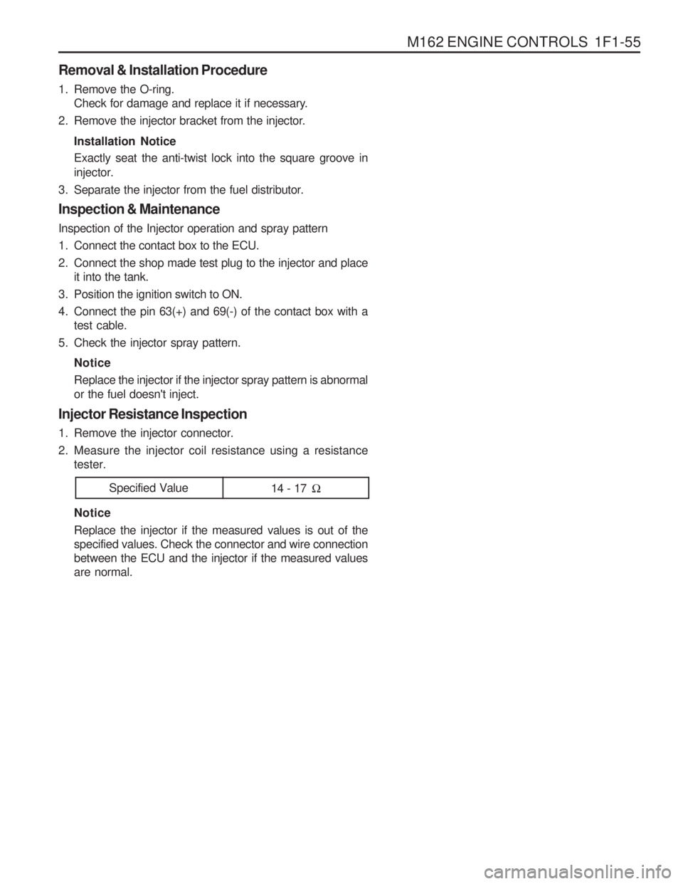
Injector Resistance Inspection
1. Remove the injector connector.
2. Measure the injector coil resistance using a resistance tester. Notice Replace the injector if the measured values is out of the specified values. Check the connector and wire connectionbetween the ECU and the injector if the measured valuesare normal.
Specified Value 14 - 17 �
Page 588 of 1574
1F1-56 M162 ENGINE CONTROLS
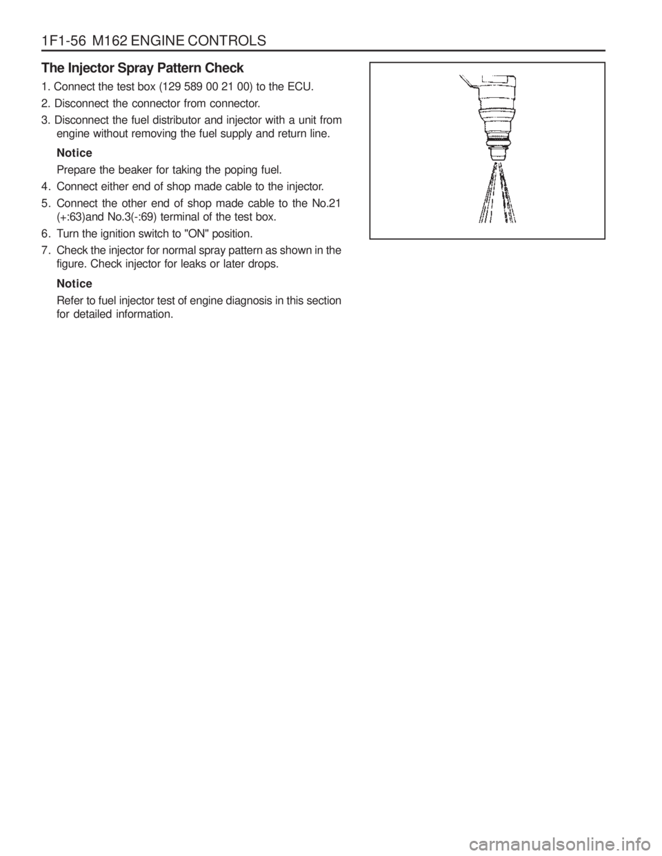
The Injector Spray Pattern Check 1. Connect the test box (129 589 00 21 00) to the ECU.
2. Disconnect the connector from connector.3. Disconnect the fuel distributor and injector with a unit fromengine without removing the fuel supply and return line. Notice Prepare the beaker for taking the poping fuel.
4. Connect either end of shop made cable to the injector.
5. Connect the other end of shop made cable to the No.21 (+:63)and No.3(-:69) terminal of the test box.
6. Turn the ignition switch to "ON" position.
7. Check the injector for normal spray pattern as shown in the figure. Check injector for leaks or later drops. Notice Refer to fuel injector test of engine diagnosis in this section for detailed information.
Page 593 of 1574
M162 ENGINE CONTROLS 1F1-61
Notice Replace the fuel pump relay if the measured value is over 9A.
Notice Check the fuel filter and fuel line when the fuel delivery is not within specified value.
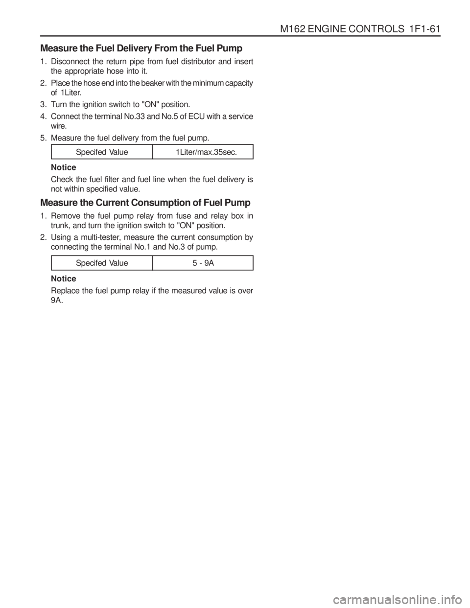
Measure the Current Consumption of Fuel Pump
1. Remove the fuel pump relay from fuse and relay box in trunk, and turn the ignition switch to "ON" position.
2. Using a multi-tester, measure the current consumption by connecting the terminal No.1 and No.3 of pump.
Measure the Fuel Delivery From the Fuel Pump
1. Disconnect the return pipe from fuel distributor and insert
the appropriate hose into it.
2 . Place the hose end into the beaker with the minimum capacity of 1Liter.
3. Turn the ignition switch to "ON" position.
4. Connect the terminal No.33 and No.5 of ECU with a service wire.
5. Measure the fuel delivery from the fuel pump.
1Liter/max.35sec.
Specifed Value
5 - 9A
Specifed Value
Page 594 of 1574
1F1-62 M162 ENGINE CONTROLS
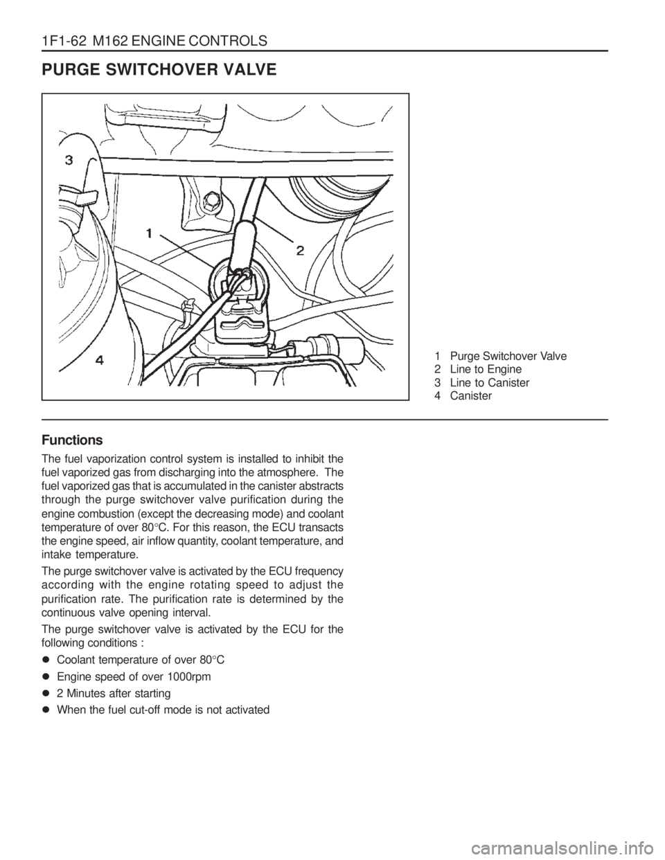
PURGE SWITCHOVER VALVE
1 Purge Switchover Valve
2 Line to Engine
3 Line to Canister
4 Canister
Functions The fuel vaporization control system is installed to inhibit the fuel vaporized gas from discharging into the atmosphere. Thefuel vaporized gas that is accumulated in the canister abstractsthrough the purge switchover valve purification during the engine combustion (except the decreasing mode) and coolant temperature of over 80 °C. For this reason, the ECU transacts
the engine speed, air inflow quantity, coolant temperature, andintake temperature. The purge switchover valve is activated by the ECU frequency according with the engine rotating speed to adjust the purification rate. The purification rate is determined by the continuous valve opening interval. The purge switchover valve is activated by the ECU for the following conditions :
� Coolant temperature of over 80 °C
� Engine speed of over 1000rpm
� 2 Minutes after starting
� When the fuel cut-off mode is not activated
Page 595 of 1574
M162 ENGINE CONTROLS 1F1-63
4. Remove the line to canister and measure the pressure withthe vacuum pressure gauge.
Test
1. Maintain the normal temperature and idling state by
operating the engine.
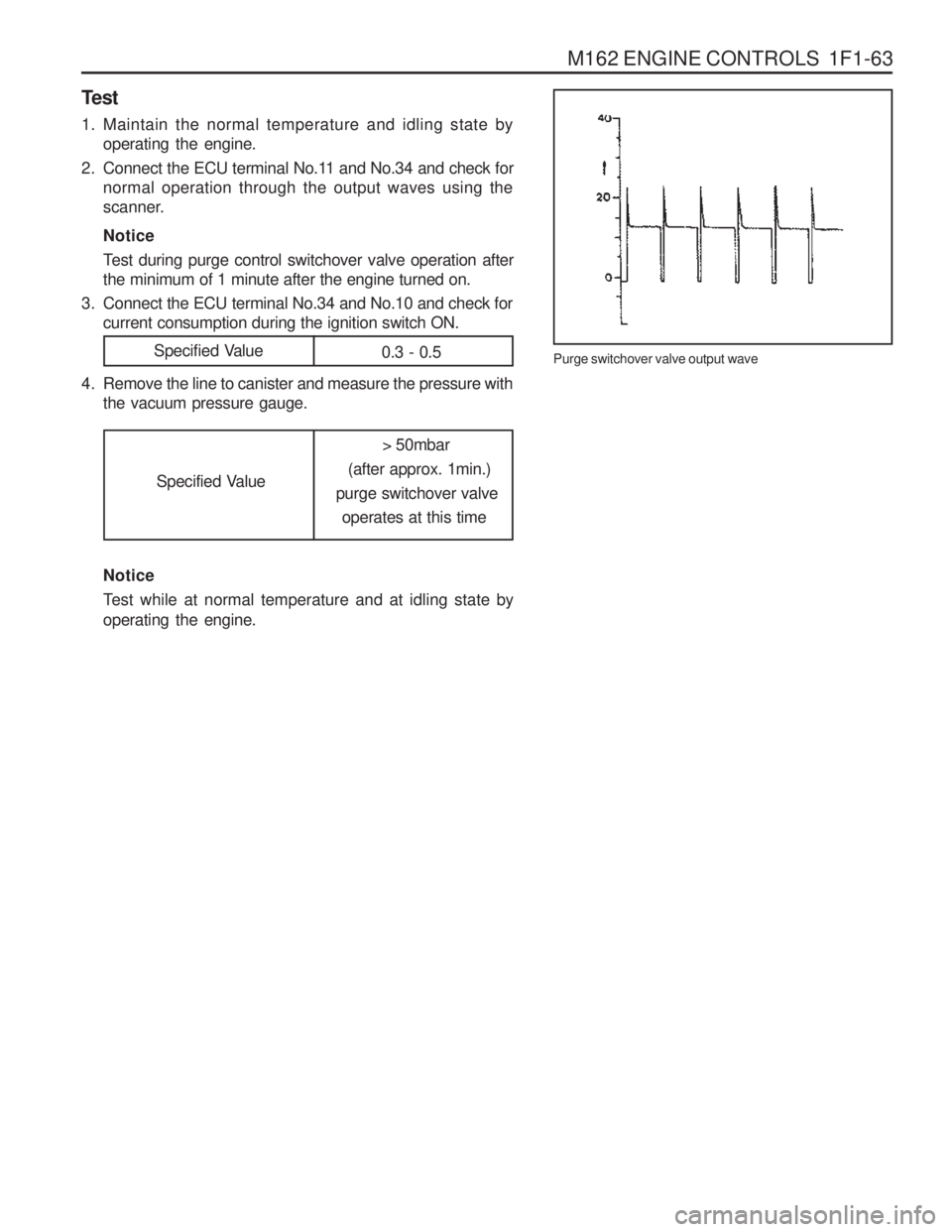
2. Connect the ECU terminal No.11 and No.34 and check for normal operation through the output waves using the
scanner. Notice
Test during purge control switchover valve operation after the minimum of 1 minute after the engine turned on.
3. Connect the ECU terminal No.34 and No.10 and check for current consumption during the ignition switch ON.
Purge switchover valve output wave
Specified Value0.3 - 0.5
Specified Value > 50mbar
(after approx. 1min.)
purge switchover valve operates at this time
Notice
Test while at normal temperature and at idling state by operating the engine.
Page 598 of 1574
1F1-66 M162 ENGINE CONTROLS Crankshaft Position Sensor Resistance Inspection
1. Disconnect the coupling "E" of ECU while the ignition switchis in "OFF" position.
2. Measure the resistance between the coupling terminal pin No.99 and No.100 using a multimeter. Notice Measure the insulator resistance of the crankshaft position sensor if out of the specified value.
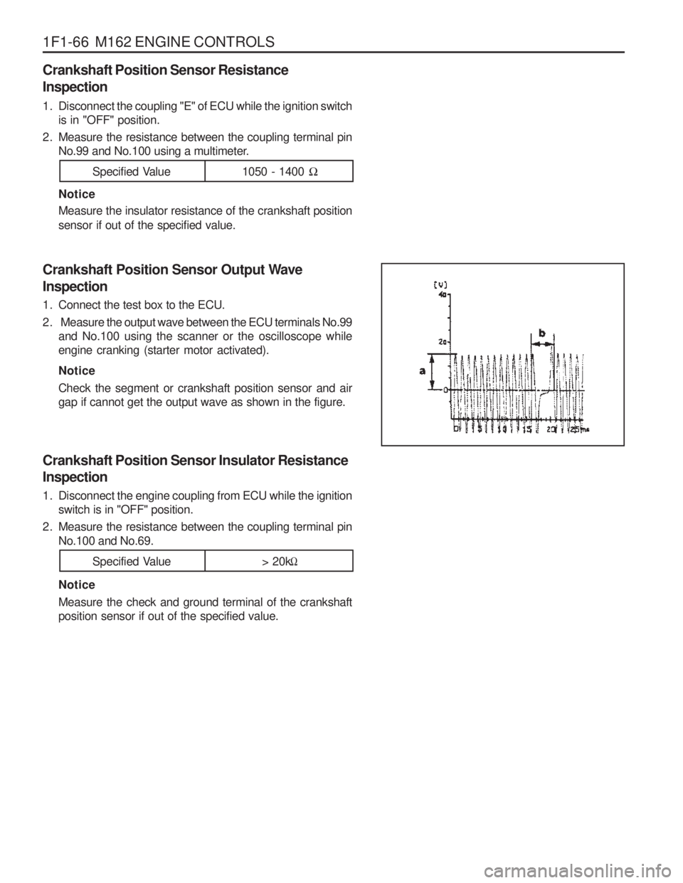
Crankshaft Position Sensor Output Wave Inspection
1. Connect the test box to the ECU.
2. Measure the output wave between the ECU terminals No.99 and No.100 using the scanner or the oscilloscope while engine cranking (starter motor activated). Notice Check the segment or crankshaft position sensor and air gap if cannot get the output wave as shown in the figure.
Specified Value 1050 - 1400 �
Specified Value > 20k�
Crankshaft Position Sensor Insulator Resistance Inspection
1. Disconnect the engine coupling from ECU while the ignition
switch is in "OFF" position.
2. Measure the resistance between the coupling terminal pin No.100 and No.69. Notice Measure the check and ground terminal of the crankshaft position sensor if out of the specified value.
Page 600 of 1574
1F1-68 M162 ENGINE CONTROLS Camshaft Position Sensor Power Supply Inspection
1. Turn the ignition switch to 'ON' position.
2. Disconnect the camshaft position sensor connector.
3. Measure the voltage between the No.1 and No.3 pin ofcamshaft position sensor while the ignition switch is in "ON" position. Notice If the measured value is not within the specified value, check the cable.
Notice The signal voltage will be changed in the range of 1.2 -
1.7V.
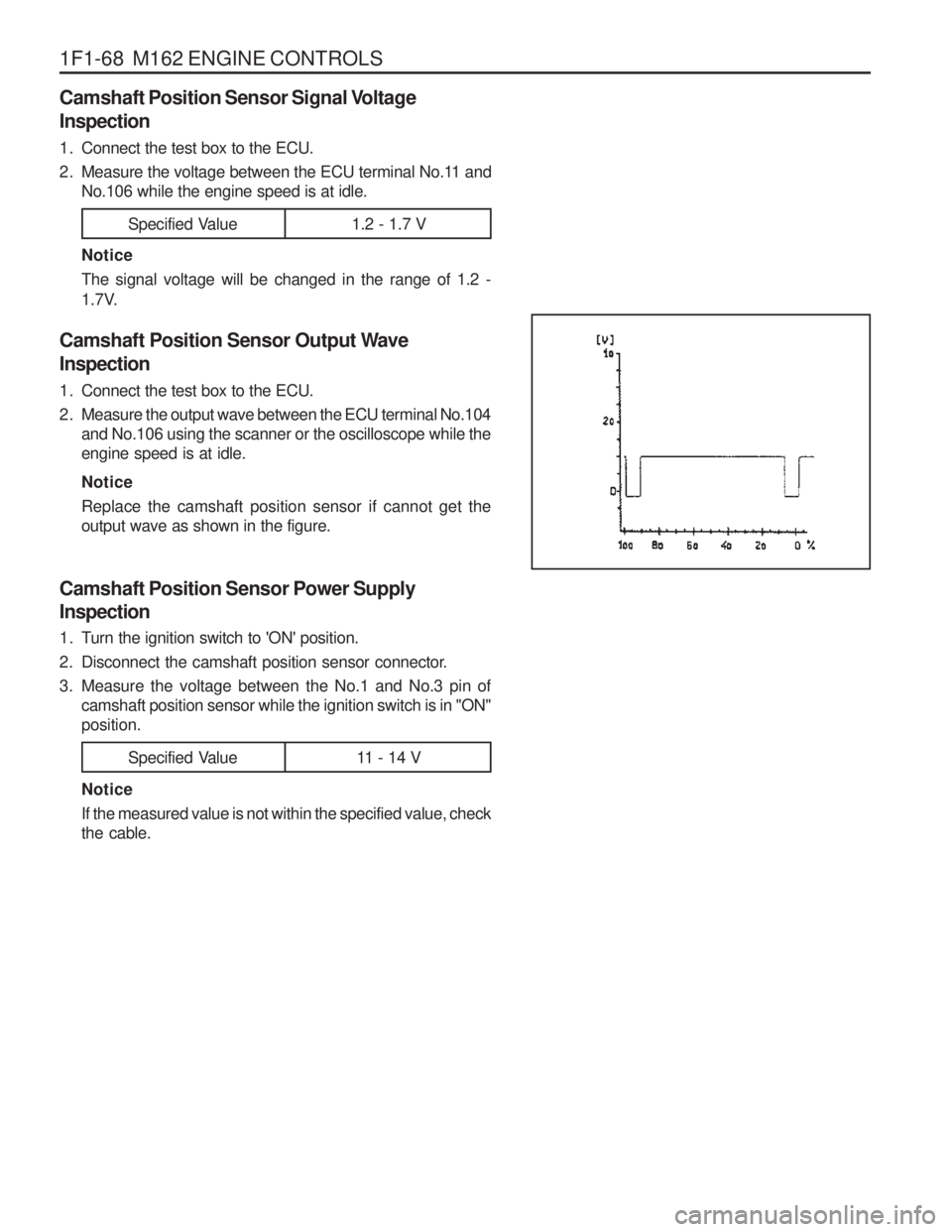
Camshaft Position Sensor Output Wave Inspection
1. Connect the test box to the ECU.
2. Measure the output wave between the ECU terminal No.104 and No.106 using the scanner or the oscilloscope while the engine speed is at idle. Notice Replace the camshaft position sensor if cannot get the output wave as shown in the figure.
Specified Value 11 - 14 V
Specified Value 1.2 - 1.7 V
Camshaft Position Sensor Signal Voltage Inspection
1. Connect the test box to the ECU.
2. Measure the voltage between the ECU terminal No.11 andNo.106 while the engine speed is at idle.
Page 603 of 1574
M162 ENGINE CONTROLS 1F1-71
If the measured value is not within the specified value, the possible cause may be in cable or HFM sensor in itself.Perform the 5V power supply inspection procedures.
HFM Sensor 5V Power Supply Inspection 1. Measure the voltage between the HFM sensor No.108 (+) and
No.105(-) after removing the HFM sensor connector.
HFM Sensor Input Voltage Inspection
1. Measure the HFM sensor signal voltage between the ECU
terminal No.103 and No.104.
Specified Value (coolant temperature is over 70 °C)
If the measured value is not within the specified value, the possible cause may be in cable or ECU coupling.
Iginition"ON ” 0.9 - 1.1 V
Engine at Idle 1.3 - 1.7 V
Specified Value 4.7 - 5.2 V
2. Measure the voltage between the HFM sensor wining connector terminal No.3 pin(-) and No.4 after removing the
HFM sensor connector.
Specified Value If the measured value is not within the specified value, the possible cause may be in cable or over voltage protection
relay. Perfrom the 12V power supple inspection procedures.
Specified Value 4.7 - 5.2 V
HFM Sensor 12V Power Supply Inspection
1. Measure the voltage between the HFM sensor wiring connector 1G No.2 pin(+) and No.104 after removing the
HFM sensor connector. If the measured value is not within the specified value, the possible cause may be in cable or over voltage protection
relay.
Specified Value 11 - 14 V
Page 604 of 1574
1F1-72 M162 ENGINE CONTROLS
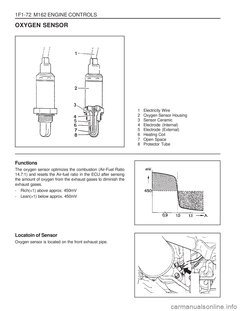
OXYGEN SENSOR
1 Electricity Wire
2 Oxygen Sensor Housing
3 Sensor Ceramic
4 Electrode (Internal)
5 Electrode (External)
6 Heating Coil
7 Open Space
8 Protector Tube
Functions The oxygen sensor optimizes the combustion (Air-Fuel Ratio 14.7:1) and resets the Air-fuel ratio in the ECU after sensingthe amount of oxygen from the exhaust gases to diminish the exhaust gases.
- Rich(<1) above approx. 450mV
- Lean(>1) below approx. 450mV
Locatoin of Sensor Oxygen sensor is located on the front exhaust pipe.
Page 605 of 1574
M162 ENGINE CONTROLS 1F1-73
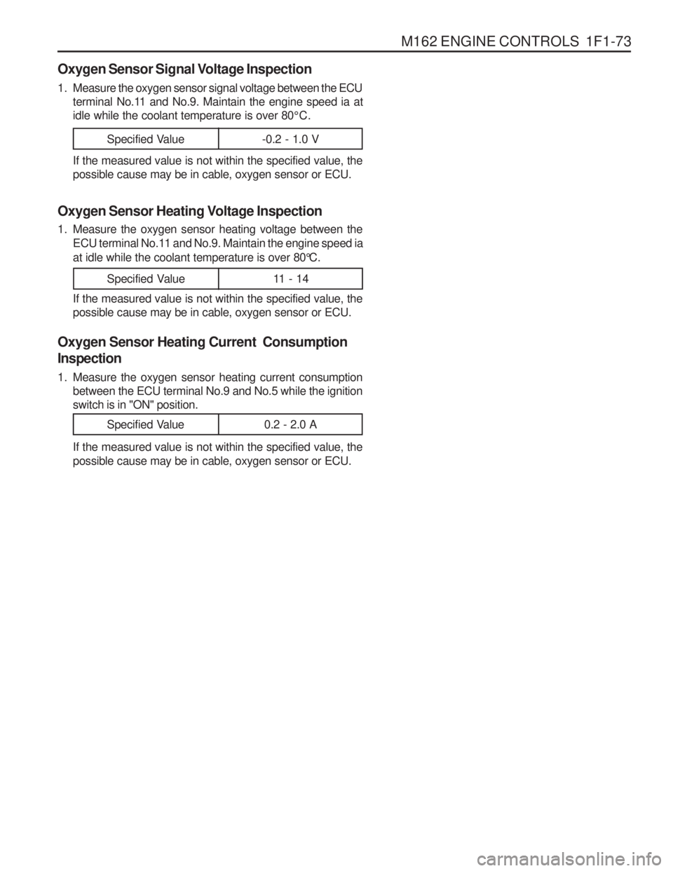
Oxygen Sensor Signal Voltage Inspection
1. Measure the oxygen sensor signal voltage between the ECUterminal No.11 and No.9. Maintain the engine speed ia at idle while the coolant temperature is over 80 °C.
If the measured value is not within the specified value, thepossible cause may be in cable, oxygen sensor or ECU.
Oxygen Sensor Heating Voltage Inspection
1. Measure the oxygen sensor heating voltage between the ECU terminal No.11 and No.9. Maintain the engine speed ia at idle while the coolant temperature is over 80 °C.
If the measured value is not within the specified value, the possible cause may be in cable, oxygen sensor or ECU.
Oxygen Sensor Heating Current Consumption
Inspection
1. Measure the oxygen sensor heating current consumption between the ECU terminal No.9 and No.5 while the ignition switch is in "ON" position. If the measured value is not within the specified value, the possible cause may be in cable, oxygen sensor or ECU.
Specified Value 0.2 - 2.0 A
Specified Value -0.2 - 1.0 V
Specified Value 11 - 14