ABS SSANGYONG MUSSO 2003 Workshop Manual
[x] Cancel search | Manufacturer: SSANGYONG, Model Year: 2003, Model line: MUSSO, Model: SSANGYONG MUSSO 2003Pages: 1574, PDF Size: 26.41 MB
Page 853 of 1574

4F-24 ANTILOCK BRAKE SYSTEM ABS/ABD 5.3 Pressure Increased
1 Master Cylinder
2 Hydraulic Unit
3 Damping Chamber
4 Return Pump
5 Return Pump Motor
6 Accumulator Chamber7 Inlet Valve for Each Wheel
8 Outlet Valve for Each Wheel
9 Wheel
10 Prime Valve (ASV) 11 Pilot Valve (USV)
12 Check V alve
13 ISD (Integrated Suction Damper)
Page 889 of 1574

5A-30 AUTOMATIC TRANSMISSION
Solenoid Valve Symbols (On/off Solenoids)
The solenoid symbol shown adjacent to each solenoid on the
hydraulic system schematics indicates the state of the oil flow
through the solenoid valve with the power On or 0ff. Refer to
figure 3.6 for the On/off operational details of NO solenoidvalves. Normally Open (NO) Solenoid POWER ON
Line 500 port is closed. The output port is open to exhaust at the solenoid valve. POWER OFF
The exhaust port is closed. The output port is open to line 500,Figure 3.6- Normally Open (NO) Symbols
Variable Pressure Solenoid Multiplexing System
Friction element shifting pressures are controlled by the variable pressure solenoid (VPS).
Line pressure is completely independent of shift pressure and is a function of throttle position, gear state and enginespeed.
S5 is a proportional or variable pressure solenoid that provides the signal pressure to the clutch and band regulator
valves thereby controlling shift pressures.
VPS pressure is multiplexed to the clutch regulator valve, the band regulator valve and the converter clutch regulator
valve during automatic gearshifts.
A variable pressure solenoid produces a hydraulic pressure inversely proportional to the current applied. During a
gearshift the TCU applies a progressively increasing or decreasing (ramped) current to the solenoid. Current applied will vary between a minimum of 200 mA and a maximum of 1000 mA, Increasing current decreases output (55)
pressure. Decreasing current increases output (55) pressure.
Line 500 pressure, (approximately 440 to 560 kPa), is the reference pressure for the VPS, and the VPS outputpressure is always below line 500 pressure.
When the VPS is at standby, that is no gearshift is taking place, the VPS current is set to 200 mA giving maximum output pressure.
Under steady state conditions the band and clutch regulator valve solenoids are switched off. This applies full Line
500 pressure to the plunger and because Line 500 pressure is always greater than S5 pressure it squeezes the S5
oil out between the regulator valve and the plunger. The friction elements are then fed oil pressure equal to Line 500multiplied by the amplification ratio.
When a shift is initiated the required On/off solenoid is switched on cutting the supply of Line 500 to the plunger.
At the same time the VPS pressure is reduced to the ramp start value and assumes control of the regulator valve by
pushing the plunger away from the valve. The VPS then carries out the required pressure ramp and the timed shift is
completed by switching Off the On/off solenoid and returning the VPS to the standby pressure.
This system enables either the band or clutch or both to be electrically controlled for each gearshift. Mode Indicator Light
Depending on the application, the mode indicator light may be used to indicate the mode that has been selected or
if an overheat condition exists. The mode indicator light is usually located on the instrument cluster. Communication Systems CAN
The controller area network (CAN) connects various control modules by using a twisted pair of wires, to share
common information. This results in a reduction of sensors and wiring. Typical applications include using the engine
controller to obtain the actual engine speed and throttle position, and adding these to the network. The ABS controller
(if fitted) can be used to obtain the road speed signal. This information is then available to the TCU without anyadditional sensors.
Page 902 of 1574

AUTOMATIC TRANSMISSION 5A-43
Figure 4.1 - Power Flow Diagram TORQUE CONVERTER
The torque converter (refer figure 4.2) consists of a turbine,
stator pump, impeller and a lock-up damper and piston
assembly. As in conventional torque converters, the impeller is
attached to the converter cover, the turbine is splined to the
input shaft and the stator is mounted on the pump housing via
a one way clutch (sprag).
The addition of the damper and piston assembly enables the
torque converter to ‘lock-up’ under favourable conditions. Lock-
up is only permitted to occur in third and fourth gears under
specified throttle and road speed conditions.
Lock-up is achieved by applying hydraulic pressure to the
damper and piston assembly which couples the turbine to the
converter cover, locking-up the converter and eliminating
unwanted slippage. Whenever lock-up occurs, improved fuel
consumption is achieved. Torsional damper springs are
provided in the damper and piston assembly to absorb anyengine torque fluctuations during lock-up. Figure 4.2 - Torque Converter Cross Section
Page 947 of 1574

5A-88 AUTOMATIC TRANSMISSION
8. Detach the No.7 solenoid wire from the front of the case.
9. Remove the parking pawl pivot pin and the pawl and springfrom the case.
10. Remove the shaft and the rear servo lever.
11. Remove the rear servo cover and piston assembly.
12. Remove the B1R circlip, valve and spring.
13. Remove both band adjustment shims.
14. Inspect the output shaft bushing in the case and replace if necessary.
15. Inspect cooler line fittings and replace as necessary.
16. Inspect the case for damage.
17. To remove the park rod lever: Remove the circlip from the inner end of the pivot shaft and tap the outer end of the
shaft until it moves free from the case, then using a wide
shallow tapered drift as a wedge, drive the pin out fromthe inside of the case and remove the lever and spring. NoticeDo not remove the park rod lever unless absolutely
necessary.
Page 1010 of 1574
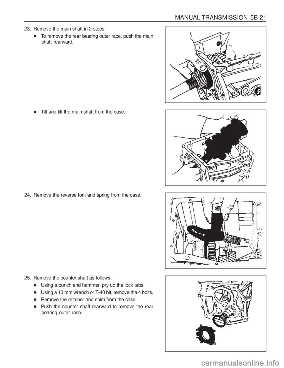
MANUAL TRANSMISSION 5B-21
23. Remove the main shaft in 2 steps.�To remove the rear bearing outer race, push the main
shaft rearward.
� Tilt and lift the main shaft from the case.
24. Remove the reverse fork and spring from the case.
25. Remove the counter shaft as follows: �Using a punch and hammer, pry up the lock tabs.
� Using a 13 mm wrench or T-40 bit, remove the 4 bolts.
� Remove the retainer and shim from the case.
� Push the counter shaft rearward to remove the rear
bearing outer race.
Page 1013 of 1574

5B-24 MANUAL TRANSMISSION
7. Install the counter shaft rear bearing outer race, shim andretainer.
Tightening Torque 39 - 52 Nm
� Using a punch and hammer, bend the lock tabs on the
retainer.
8. Install the following parts : � Install the main shaft into case.
� Install the main shaft rear bearing outer race into the
rear of the case.
� Install the 4th speed blocking ring onto the front of the
main shaft.
� Install the input shaft onto the front of the main shaft.
� Install the input bearing retainer without shim onto the
front of the case.
� Using a torque wrench, tighten the 4 bolts.
9. Install the 5th speed drive gear and blocking ring on the counter shaft.
10. Install the 5th synchronizer and rail/fork.
11. Install the 5th synchronizer snap ring and oiling funnel.
12. Align the slots of the lever with the rollers of the reverse fork and 5th shift rail. Apply sealer on the 5-R lever pivot bolt and install it into the case.
Tightening Torque 28 Nm
13. Using a needle nose pliers, install the 5-R lever clip.
Page 1079 of 1574
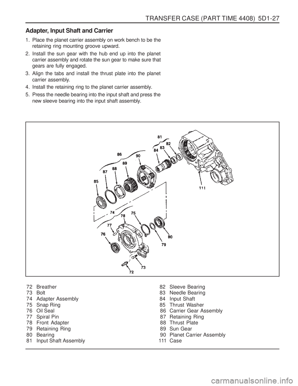
TRANSFER CASE (PART TIME 4408) 5D1-27
Adapter, Input Shaft and Carrier72 Breather
73 Bolt
74 Adapter Assembly
75 Snap Ring
76 Oil Seal
77 Spiral Pin
78 Front Adapter
79 Retaining Ring
80 Bearing
81 Input Shaft Assembly
1. Place the planet carrier assembly on work bench to be the
retaining ring mounting groove upward.
2. Install the sun gear with the hub end up into the planet carrier assembly and rotate the sun gear to make sure that gears are fully engaged.
3. Align the tabs and install the thrust plate into the planet carrier assembly.
4. Install the retaining ring to the planet carrier assembly.
5. Press the needle bearing into the input shaft and press the new sleeve bearing into the input shaft assembly.
82 Sleeve Bearing
83 Needle Bearing
84 Input Shaft
85 Thrust Washer86 Carrier Gear Assembly
87 Retaining Ring
88 Thrust Plate
89 Sun Gear
90 Planet Carrier Assembly
111 Case
Page 1095 of 1574
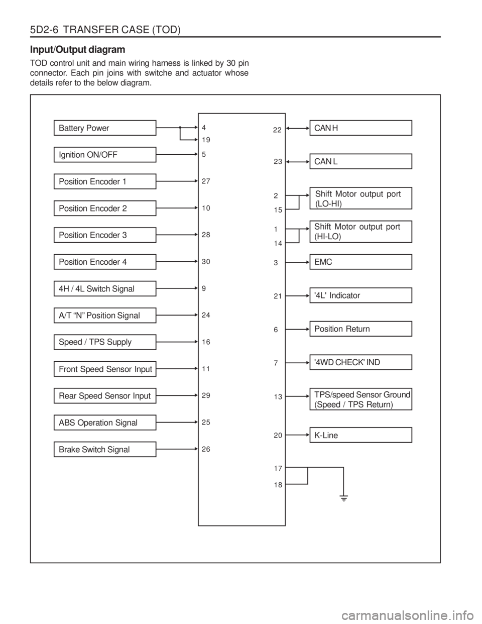
5D2-6 TRANSFER CASE (TOD) Input/Output diagram TOD control unit and main wiring harness is linked by 30 pin
connector. Each pin joins with switche and actuator whosedetails refer to the below diagram.
Battery Power
Ignition ON/OFF
Position Encoder 1
Position Encoder 2
Position Encoder 3
Position Encoder 4
4H / 4L Switch Signal
A/T “N” Position Signal
Speed / TPS Supply
Front Speed Sensor Input
Rear Speed Sensor Input
ABS Operation Signal
Brake Switch Signal
4 5271028309241611292526
19 CAN H
CAN L
Shift Motor output port (LO-HI)
Shift Motor output port (HI-LO)
EMC
'4L' Indicator
Position Return
'4WD CHECK' IND
TPS/speed Sensor Ground (Speed / TPS Return)
2 13216713
1514
K-Line
20
22
23
17 18
Page 1096 of 1574
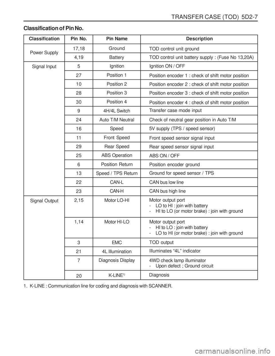
TRANSFER CASE (TOD) 5D2-7
1. K-LINE : Communication line for coding and diagnosis with SCANNER.
Classification of Pin No.
Classification
Pin No. Pin Name Description
Power Supply 17,18
Ground
TOD control unit ground
4,19 Battery TOD control unit battery supply : (Fuse No 13,20A)
5 Ignition Ignition ON / OFF
27 Position 1
Position encoder 1 : check of shift motor position
10 Position 2 Position encoder 2 : check of shift motor position
28 Position 3
Position encoder 3 : check of shift motor position
30 Position 4
Position encoder 4 : check of shift motor position
9 4H/4L Switch Transfer case mode input
24 Auto T/M Neutral Check of neutral gear position in Auto T/M 16 Speed 5V supply (TPS / speed sensor)
11 Front Speed
Front speed sensor signal input
Signal Input
29 Rear Speed Rear speed sensor signal input
25 ABS Operation
ABS ON / OFF
6 Position Return
Position encoder ground
13 Speed / TPS Return Ground for speed sensor / TPS
2 2 CAN-L CAN bus low line
23 CAN-H
CAN bus high line
2,15 Motor LO-HI Motor output port
- LO to HI : join with battery
- HI to LO (or motor brake) : join with ground
1,14 Motor HI-LO Motor output port
- HI to LO : join with battery
- LO to HI (or motor brake) : join with ground
3 EMC TOD output
Signal Output
21 4L Illumination Illuminates
“4L ” indicator
7 Diagnosis Display
4WD check lamp illuminator
- Upon defect ; Ground circuit
20K-LINE1)
Diagnosis
Page 1100 of 1574
TRANSFER CASE (TOD) 5D2-11
4. Electric Shift Default ModeIf the motor fails to reach its destination, the TCCU will attempt the following (in order):
a. The TCCU will wait 3 seconds then attempt the shift again.
b. If the second attempt to reach the destination fails the TCCU will wait 3 seconds then attempt to rotate the motor back to the original position. If successful, all future shifts will be inhibited until the Ignition is cycled.
c. If the attempt to return to the original position fails, the TCCU will wait 3 seconds then attempt to rotate the motor to the original position again. If the second attempt to return to the original position is successful, the “4WD CHECK ” lamp will be illuminated, and all future shifts will be inhibited until the Ignition is cycled.
d. If the second attempt to return to the original position fails the motor will be turned off, the “4WD CHECK ” lamp
will be illuminated, and all future shifts will be inhibited until the Ignition is cycled.
TOD TM
System Operation
The TOD TM
System is responsible for distributing torque between the front and rear axles. The TCCU monitors the
propshaft speeds, operating range (High/Low), and ABS activity and then applies a calculated amount of torque tothe front axle by Pulse Width Modulating the current applied to the EMC.
1. Touch-off Torque
The minimum EMC Duty Cycle is based on the vehicle speed and throttle positionThe TCCU receives the TPS signal from the following sources:On vehicles equipped with CAN, the TCCU receives the TPS signal from the CAN bus.
2. When Slip Detection
The TCCU continuously monitors the front and rear propshaft speeds to detect wheel slip.
3. Wheel Slip Control When wheel slip is detected the TCCU controls the EMC duty cycle as necessary until the wheel slip is reduced
below the allowable limit. The EMC Duty Cycle will then be reduced to the Touch-Off value.
4. Brake/ABS Strategy When the ABS System is active, the EMC Duty Cycle is set to a fixed duty cycle (30%) to aid in braking without counteracting the ABS System.
5. 4L Strategy When the system is operating in 4L, the TCCU continues TOD TM
(operation provided that the propshaft speed is
below 175 rpm (5220 pulses/minute)). When the speed increases above 175 rpm, the EMC Duty Cycle is set tothe maximum value (88%) which applies the maximum available torque to the front axle.