ESP SSANGYONG MUSSO 2003 Service Manual
[x] Cancel search | Manufacturer: SSANGYONG, Model Year: 2003, Model line: MUSSO, Model: SSANGYONG MUSSO 2003Pages: 1574, PDF Size: 26.41 MB
Page 85 of 1574
M162 ENGINE MECHANICAL 1B1-49
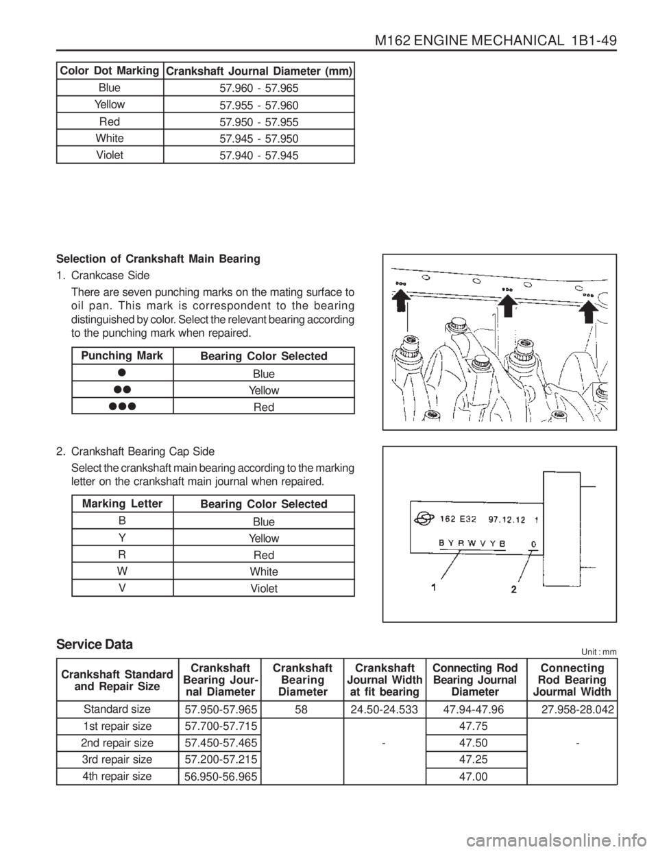
Selection of Crankshaft Main Bearing
1. Crankcase SideThere are seven punching marks on the mating surface to oil pan. This mark is correspondent to the bearing
distinguished by color. Select the relevant bearing according to the punching mark when repaired.
2. Crankshaft Bearing Cap Side Select the crankshaft main bearing according to the markingletter on the crankshaft main journal when repaired.
Color Dot Marking
Blue
Yellow
Red
White VioletCrankshaft Journal Diameter (mm)
57.960 - 57.965 57.955 - 57.960 57.950 - 57.95557.945 - 57.95057.940 - 57.945
Punching Mark
Bearing Color Selected
Blue
Yellow
Red
Marking Letter
B Y
R
W VBearing Color Selected
Blue
Yellow
Red
White Violet
Service Data Unit : mm
Crankshaft
Bearing Jour- nal Diameter Crankshaft
Bearing
Diameter Crankshaft
Journal Width at fit bearing Connecting Rod
Bearing Journal Diameter Connecting
Rod Bearing
Jourmal Width
Standard size
1st repair size
2nd repair size 3rd repair size4th repair size 57.950-57.965 57.700-57.71557.450-57.46557.200-57.215
56.950-56.965 58 24.50-24.533
-47.94-47.96
47.7547.5047.25 47.00 27.958-28.042
-
Crankshaft Standard
and Repair Size
Page 101 of 1574
M162 ENGINE MECHANICAL 1B1-65
Adjustment Procedure
1. Position the No.1 cylinder to BTDC 30° .
2. Remove the chain tensioner.
3. Remove the exhaust camshaft sprocket.
4. Align the intake and exhaust camshaft flange hole with the cylinder head upper surface.
� Intake Side : 3 o ’clock direction
� Exhaust Side : 9 o ’clock direction
5. Secure the intake and exhaust camshaft.
6. Position the piston of No.1 cylinder at TDC (OT) by turning the crankshaft.
7. Turn the camshaft adjuster of the intake camshaft to the left as much as possible (cam adjuster ‘retarded ’ position).
8. Install the chain to the intake camshaft sprocket.
Notice
Timing chain must be placed on the guide rail in gear case
cover.
Tools Required 104 589 01 01 00
Spanner
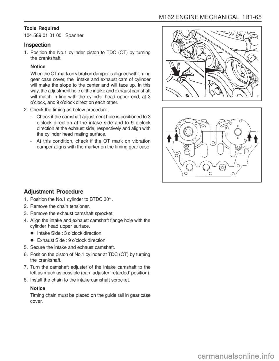
Inspection
1. Position the No.1 cylinder piston to TDC (OT) by turning the crankshaft. Notice When the OT mark on vibration damper is aligned with timing
gear case cover, the intake and exhaust cam of cylinderwill make the slope to the center and will face up. In this
way, the adjustment hole of the intake and exhaust camshaft will match in line with the cylinder head upper end, at 3
o’clock, and 9 o ’clock direction each other.
2. Check the timing as below procedure; - Check if the camshaft adjustment hole is positioned to 3 o’clock direction at the intake side and to 9 o ’clock
direction at the exhaust side, respectively and align withthe cylinder head mating surface.
- At this condition, check if the OT mark on vibration damper aligns with the marker on the timing gear case.
Page 208 of 1574
1B2-56 M161 ENGINE MECHANICAL Selection of Crankshaft Main Bearing
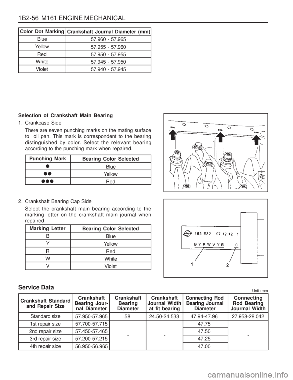
1. Crankcase SideThere are seven punching marks on the mating surface to oil pan. This mark is correspondent to the bearing
distinguished by color. Select the relevant bearing according to the punching mark when repaired.
2. Crankshaft Bearing Cap Side Select the crankshaft main bearing according to themarking letter on the crankshaft main journal whenrepaired.
Color Dot Marking
Blue
Yellow
Red
White VioletCrankshaft Journal Diameter (mm)
57.960 - 57.965 57.955 - 57.960 57.950 - 57.95557.945 - 57.95057.940 - 57.945
Punching Mark
Bearing Color Selected
Blue
Yellow
Red
Marking Letter
B Y
R
W VBearing Color Selected
Blue
Yellow Red
White Violet
Service Data Unit : mm
Crankshaft
Bearing Jour- nal Diameter Crankshaft
Bearing
Diameter Crankshaft
Journal Width at fit bearing Connecting Rod
Bearing Journal Diameter Connecting
Rod Bearing
Jourmal Width
Standard size
1st repair size
2nd repair size 3rd repair size4th repair size 57.950-57.965 57.700-57.71557.450-57.46557.200-57.215
56.950-56.965 58 24.50-24.533 47.94-47.96
47.75 47.5047.25 47.0027.958-28.042
Crankshaft Standard
and Repair Size
-
--
Page 367 of 1574
1B3-102 OM600 ENGINE MECHANICAL
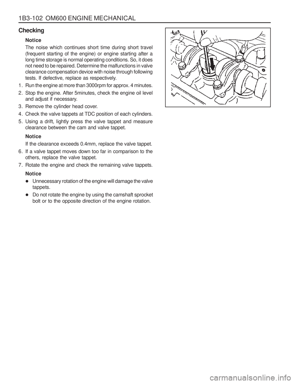
CheckingNotice The noise which continues short time during short travel (frequent starting of the engine) or engine starting after a long time storage is normal operating conditions. So, it doesnot need to be repaired. Determine the malfunctions in valveclearance compensation device with noise through following
tests. If defective, replace as respectively.
1. Run the engine at more than 3000rpm for approx. 4 minutes.
2. Stop the engine. After 5minutes, check the engine oil level and adjust if necessary.
3. Remove the cylinder head cover.
4. Check the valve tappets at TDC position of each cylinders.
5. Using a drift, lightly press the valve tappet and measure clearance between the cam and valve tappet. Notice If the clearance exceeds 0.4mm, replace the valve tappet.
6. If a valve tappet moves down too far in comparison to the others, replace the valve tappet.
7. Rotate the engine and check the remaining valve tappets.
Notice
� Unnecessary rotation of the engine will damage the valve tappets.
� Do not rotate the engine by using the camshaft sprocket bolt or to the opposite direction of the engine rotation.
Page 406 of 1574
OM600 ENGINE MECHANICAL 1B3-141
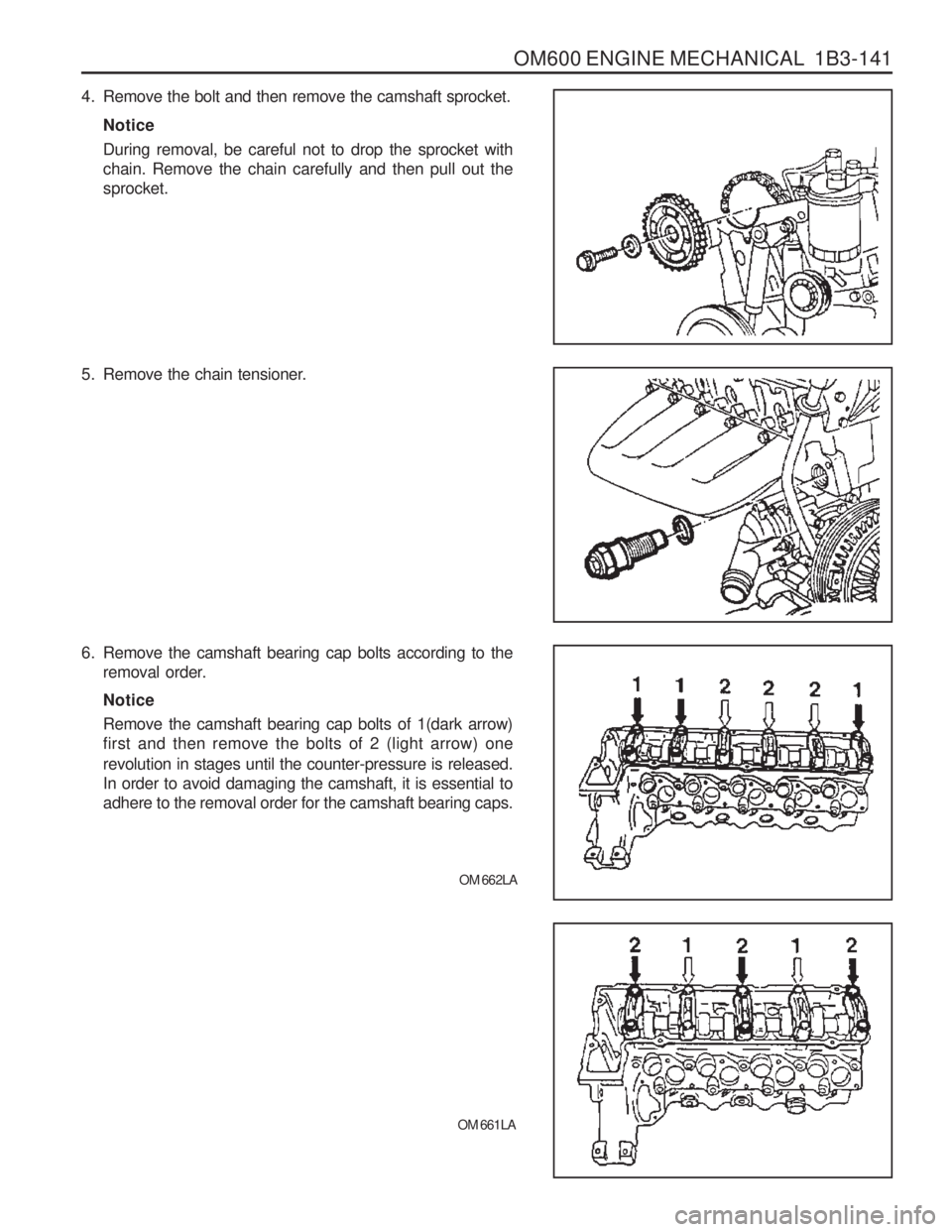
4. Remove the bolt and then remove the camshaft sprocket.Notice During removal, be careful not to drop the sprocket with chain. Remove the chain carefully and then pull out thesprocket.
5. Remove the chain tensioner.
6. Remove the camshaft bearing cap bolts according to the removal order. Notice Remove the camshaft bearing cap bolts of 1(dark arrow) first and then remove the bolts of 2 (light arrow) one revolution in stages until the counter-pressure is released. In order to avoid damaging the camshaft, it is essential toadhere to the removal order for the camshaft bearing caps.
OM 662LA
OM 661LA
Page 528 of 1574
1E3-4 OM600 ENGINE ELECTRICAL
Preheating System Operation
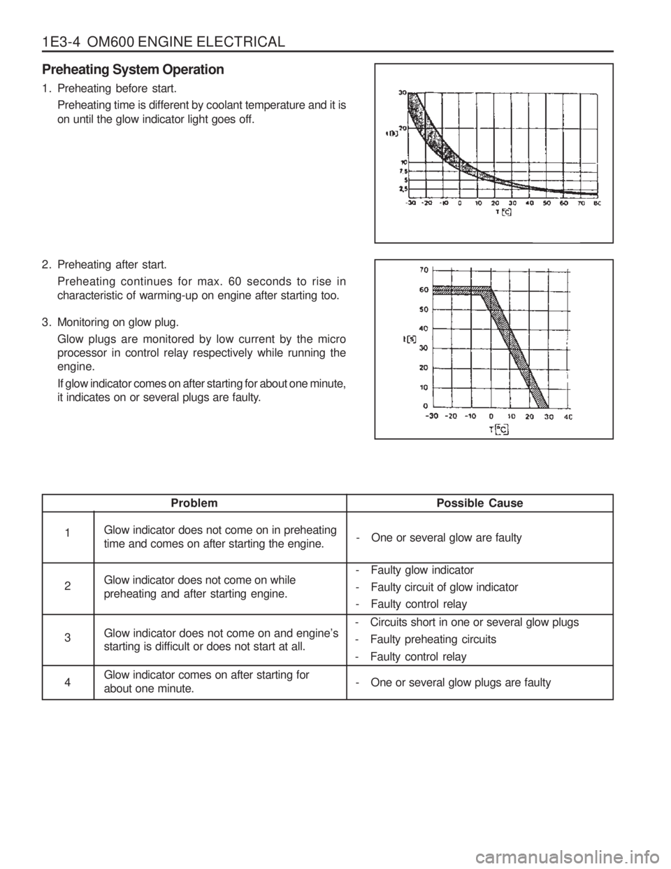
1. Preheating before start.Preheating time is different by coolant temperature and it is on until the glow indicator light goes off.
2. Preheating after start. Preheating continues for max. 60 seconds to rise in characteristic of warming-up on engine after starting too.
3. Monitoring on glow plug. Glow plugs are monitored by low current by the microprocessor in control relay respectively while running theengine. If glow indicator comes on after starting for about one minute,
it indicates on or several plugs are faulty.
Possible Cause
- One or several glow are faulty
Problem
Glow indicator does not come on in preheating time and comes on after starting the engine. Glow indicator does not come on while preheating and after starting engine. Glow indicator does not come on and engine
’s
starting is difficult or does not start at all. Glow indicator comes on after starting for about one minute.1 2 3 4 - Faulty glow indicator
- Faulty circuit of glow indicator
- Faulty control relay
- Circuits short in one or several glow plugs
- Faulty preheating circuits
- Faulty control relay
- One or several glow plugs are faulty
Page 633 of 1574
OM600 ENGINE CONTROLS 1F3-23
Tools Required
000 589 14 27 00 Tester Notice When testing the injection nozzle, do not place your hand into the spray of a nozzle. The spray will penetrate deep into the skin and destroy the tissue.
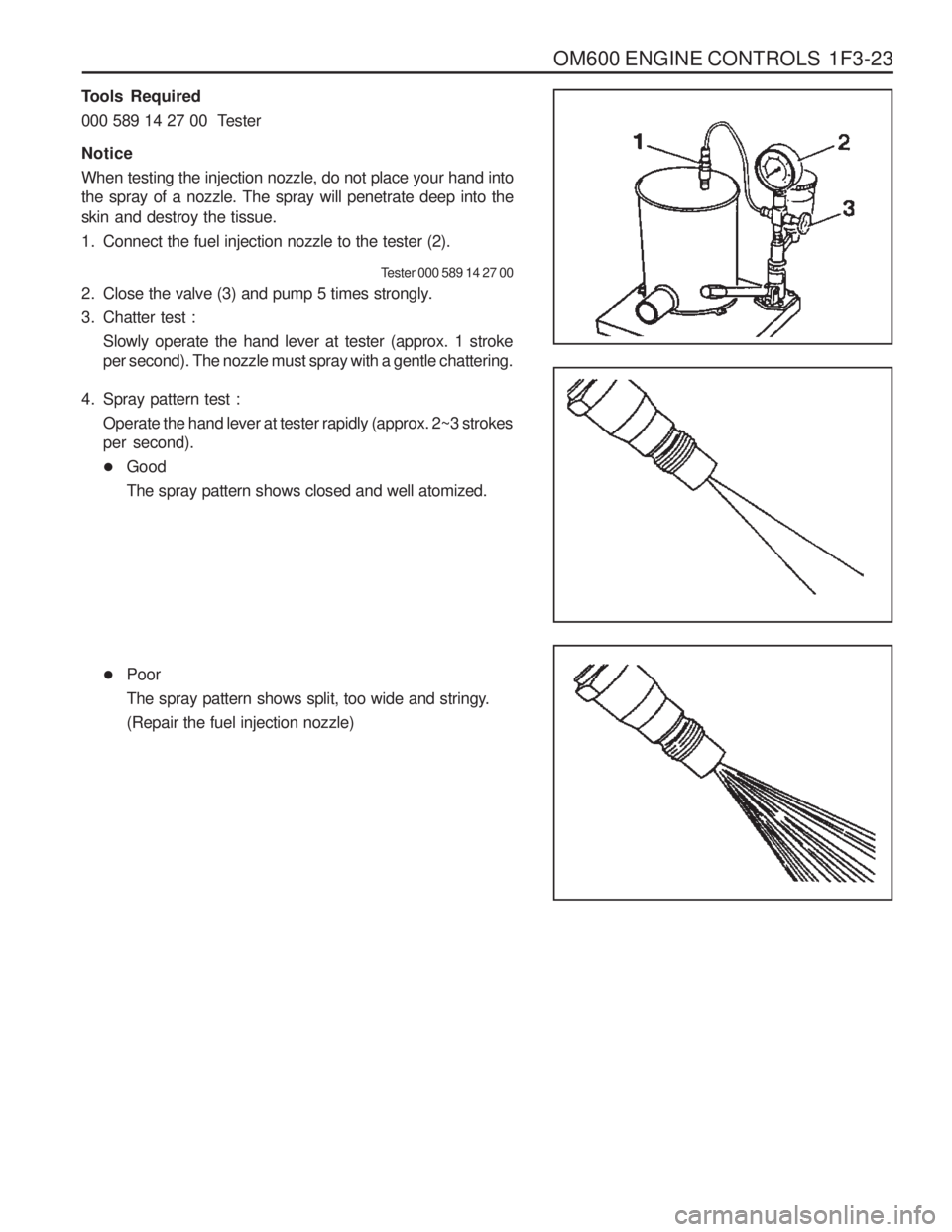
1. Connect the fuel injection nozzle to the tester (2).
Tester 000 589 14 27 00
2. Close the valve (3) and pump 5 times strongly.
3. Chatter test :
Slowly operate the hand lever at tester (approx. 1 stroke per second). The nozzle must spray with a gentle chattering.
4. Spray pattern test : Operate the hand lever at tester rapidly (approx. 2~3 strokesper second).
� GoodThe spray pattern shows closed and well atomized.
�Poor
The spray pattern shows split, too wide and stringy.(Repair the fuel injection nozzle)
Page 719 of 1574
WHEEL ALIGNMENT 2B-9
GENERAL DESCRIPTION AND SYSTEM OPERATION
FOUR WHEEL ALIGNMENT CASTER Caster is the tilting 91 the uppermost point of the steering axis either forward or backward from the vertical when viewed from the side of the vehicle. A backward tilt is positive, and a forward tilt is negative. Caster influencesdirectional control of the steering but does not affect
tire wear. Weak springs or overloading a vehicle will affect
caster. One wheel with more positive caster will pull
toward the center of the car. This condition will cause the car to move or lean toward the side with the least
amount of positive caster. Caster is measured in degrees. CAMBER Camber is the tilting of the top of the tire from the vertical when viewed from the front of the vehicle. When thetires tilt outward, the camber is positive. When the tires tilt inward, the camber is negative. The camber angle is measured in degrees from the vertical. Camber
influences both directional control and tire wear.
If the vehicle has too much positive camber, the outside
shoulder of the tire will wear. If the vehicle has too much
negative camber, the inside shoulder of the tire will wear.
The first responsibility of engineering is to design safesteering and suspension systems. Each componentmust be strong enough to withstand and absorb extremepunishment. Both the steering system and the front and the rear suspension must function geometrically with thebody mass. The steering and the suspension systems require that the front wheels self-return and that the tire rolling effortand the road friction be held to a negligible force in orderto allow the customer to direct the vehicle with the least effort and the most comfort. A complete wheel alignment check should include
measurements of the rear toe and camber. Four-wheel alignment assures that all four wheels will be running in precisely the same direction. When the vehicle is geometrically aligned, fuel economy and tire life are at their peak, and steering andperformance are maximized. TOE
Toe-in is the turning in of the tires, while toe-out is the turning out of the tires from the geometric centerline or thrust line. The toe ensures parallel rolling of the wheels. The toe serves to offset the small deflections of the wheel support system which occur when the vehicle is rollingforward. The specified toe angle is the setting whichachieves 0 degrees of toe when the vehicle is moving. Incorrect toe-in or toe-out will cause tire wear and
reduced fuel economy. As the individual steering andsuspension components wear from vehicle mileage,
additional toe will be needed to compensate for the wear. Always correct the toe dimension last.
Page 779 of 1574
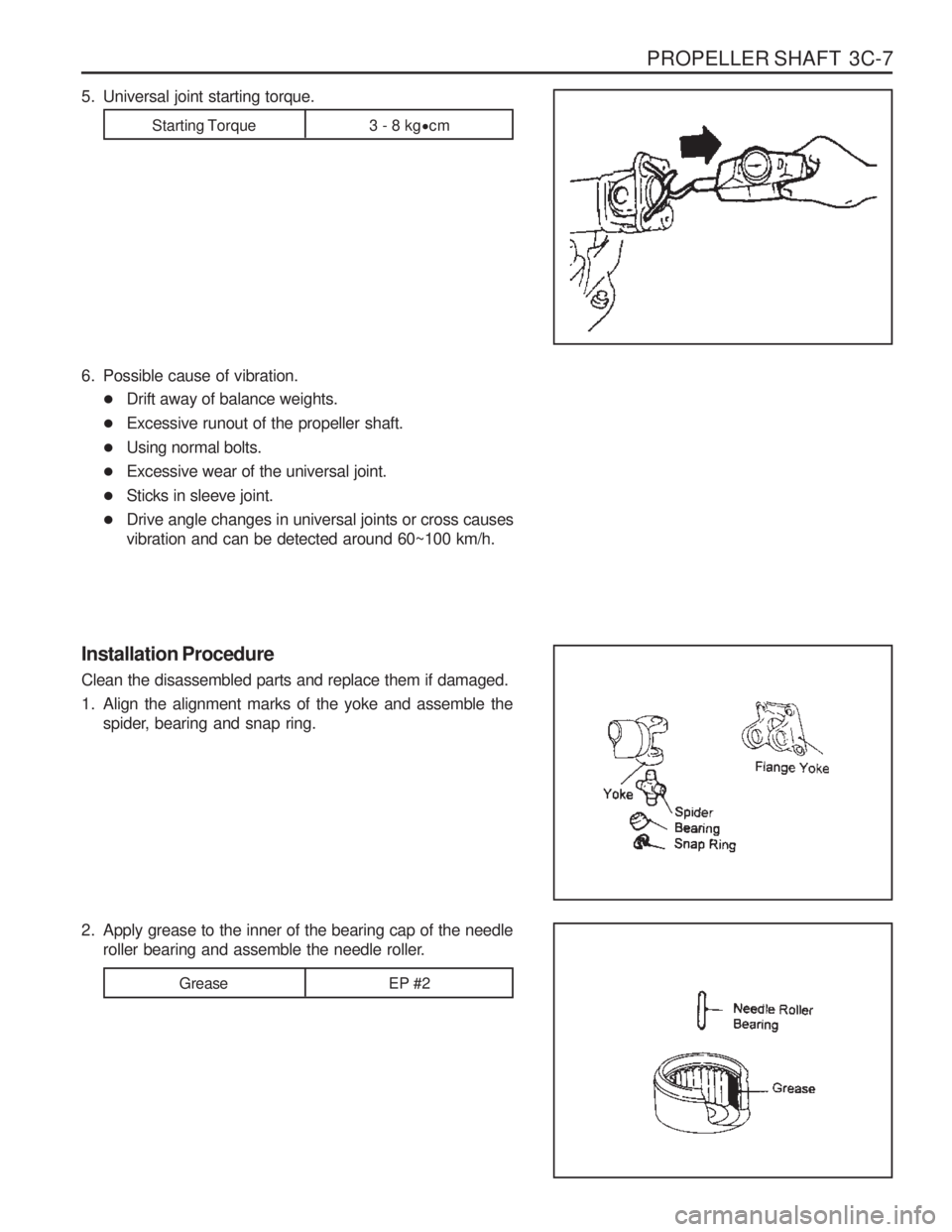
PROPELLER SHAFT 3C-7
Installation Procedure Clean the disassembled parts and replace them if damaged.
1. Align the alignment marks of the yoke and assemble thespider, bearing and snap ring.
2. Apply grease to the inner of the bearing cap of the needle roller bearing and assemble the needle roller.
Grease EP #2
6. Possible cause of vibration.
� Drift away of balance weights.
� Excessive runout of the propeller shaft.
� Using normal bolts.
� Excessive wear of the universal joint.
� Sticks in sleeve joint.
� Drive angle changes in universal joints or cross causes vibration and can be detected around 60~100 km/h.
5. Universal joint starting torque.
Starting Torque 3 - 8 kg
�
cm
Page 845 of 1574

4F-16 ANTILOCK BRAKE SYSTEM
Description
� Check terminals for open or short. (When connector is removed)
� Replace the hydraulic modulator.
� Check each valve by using SCANNER's solenoid valve overriding function.
� Check connection of connector and terminals in the
ECU hydraulic modulator.
� Check terminals for open or short. (When connector is removed)
� Replace the hydraulic modulator
� Check solenoid internal resistance of the prime(ASV) valve and pilot valve(USV) : 8.04 - 9.04 �
� Check each valve by using SCANNER's solenoid valve overriding function.
� Check connection of connector and terminals in the
ECU and hydraulic modulator.
� Check terminals for open or short.(When connector is removed)
� Replace the hydraulic modulator
� Check solenoid internal resistance of the prime(ASV)valve and pilot valve(USV) : 8.04 - 9.04 �
� Check each valve by using SCANNER's solenoid valveoverriding function.
� Check connection of connector and terminals in the
ECU and hydraulic modulator.
� Check terminals for open or short.(When connector is removed)
� Replace the hydraulic modulator
� Check each valve by using SCANNER's pump motoroverriding function.
� Check resistance between pump motor ground ter-minal and battery negative terminal : total resistanceshould be less than 15 m �
� Check body ground location.
� Check relay supply voltage : IGN on : 11 - 14 V
� Relay coil internal resistance : 70 - 80 �
� Replace the hydraulic modulator
� Check by using SCANNER's stop lamp switch diag-nosing function from sensor value output function.
� Check connection of ECU connector side stop lamp switch terminal.
� Check resistance of the stop lamp, switch.
- Each end resistance value of the switch
Application
Rear / Right OUTLET Valve Function and Response of The
Valve Function and Response of The
Valve Motor Relay / Circulation Pump Stop Lamp SwitchDefect Code
20 21 2224 27