Reverse back up SSANGYONG MUSSO 2003 Service Manual
[x] Cancel search | Manufacturer: SSANGYONG, Model Year: 2003, Model line: MUSSO, Model: SSANGYONG MUSSO 2003Pages: 1574, PDF Size: 26.41 MB
Page 644 of 1574

1F3-34 OM600 ENGINE CONTROLS
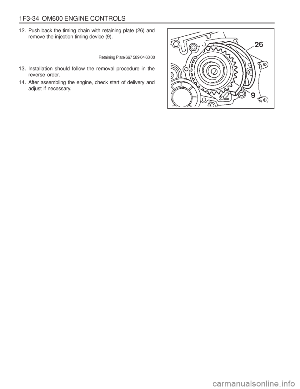
12. Push back the timing chain with retaining plate (26) and remove the injection timing device (9).
Retaining Plate 667 589 04 63 00
13. Installation should follow the removal procedure in the reverse order.
14. After assembling the engine, check start of delivery and adjust if necessary.
Page 788 of 1574

3D-8 REAR DRIVE AXLE
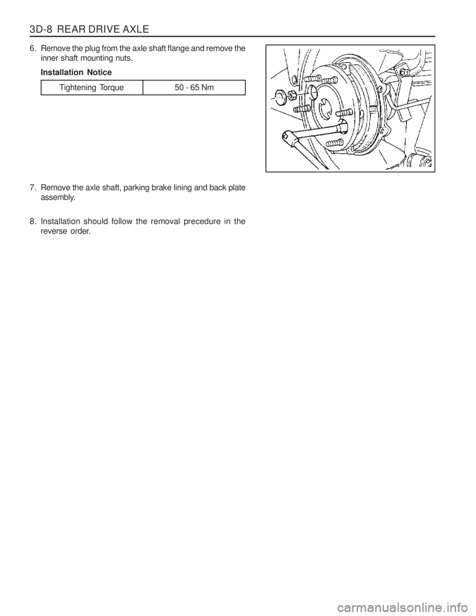
Tightening Torque 50 - 65 Nm
6. Remove the plug from the axle shaft flange and remove theinner shaft mounting nuts. Installation Notice
7. Remove the axle shaft, parking brake lining and back plate assembly.
8. Installation should follow the removal precedure in the reverse order.
Page 883 of 1574

5A-24 AUTOMATIC TRANSMISSION
Transmission Control Unit(TCU)
The TCU is an in-vehicle micro-processor based transmission management system. It is usually mounted in the
vehicle cabin, under the instrument panel, under the seat, behind the side kick panels or under the floor in the
footwell on the passenger side. Different control units are supplied for different vehicle applications.The TCU contains:
� Processing logic circuits which include a central microcontroller and a back-up memory system.
� Input circuits.
� Output circuits which control external devices such as the variable pressure solenoid (VPS), on/off solenoid
drivers, a diagnostics output and the driving mode indicator light.
The various items which make up the TCU are discussed below.
Processing Logic
Shift schedule and calibration information is stored in an erasable programmable read only memory (EEPROM).
Throttle input calibration constants and the diagnostics information are stored in electrically erasable programmable
read only memory (EEPROM) that retains the memory even when power to the TCU is disconnected. In operation the software continuously monitors the input values and uses these, via the shift schedule, to determine the required gear state, At the same time it monitors, via the solenoid outputs, the current gear state. Whenever the
input conditions change such that the required gear state is different to the current gear state, the TCU initiates a
gear shift to bring the two states back into line.
Once the TCU has determined the type of gear shift required the software accesses the shift logic, estimates the
engine torque output, adjusts the variable pressure solenoid ramp pressure then executes the shift.
The TCU continuously monitors every input and output circuit for short or open circuits and operating range. When
a failure or abnormal operation is detected the TCU records the condition code in the diagnostics memory and
implements a limp mode, The actual limp mode used depends upon the failure detected with the object to maintain
maximum driveability without damaging the transmission. In general input failures are handled by providing a default
value. Output failures, which are capable of damaging the transmission, result in full limp mode giving only third or
fourth gear and reverse. For further details of limp modes and memory retention refer to the Diagnostic Section.
The TCU is designed to operate at ambient temperatures between -40 and 85°C . It is also protected against
electrical noise and voltage spikes, however all the usual precautions should be observed, for example when arc welding or jump starting. TCU Inputs
To function correctly, the TCU requires engine speed, road speed, transmission sump temperature, throttle position
and gear position inputs to determine the variable pressure solenoid current ramp and on/off solenoid states. This
ensures the correct gear selection and shift feel for all driving conditions. The inputs required by the TCU are as follows: � Engine Speed
The engine speed signal is derived from the tachometer signal line, a dedicated sensor or a Controlled Area Network (CAN).
� Road Speed
4WD (Diesel) - The shaft speed signal is derived from the speedo sensor located on the transfer case. This signal is transmitted directly to the TCU.
4WD (Gasoline) - The speedo sensor sends the shaft speed signal to the engine control module (ECM). The
information is then transferred to the TCU via the CAN.
� Transmission Sump Temperature
The transmission sump temperature sensor is a thermistor located in the solenoid wiring loom within the transmission.
This sensor is a typical NTC resistor with low temperatures producing a high resistance and high temperatures
Page 898 of 1574

AUTOMATIC TRANSMISSION 5A-39
Primary Regulator Valve
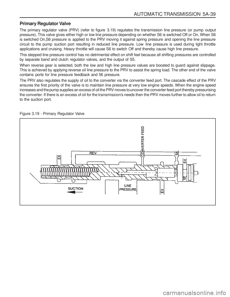
The primary regulator valve (PRV) (refer to figure 3.19) regulates the transmission line pressure (or pump output
pressure). This valve gives either high or low line pressure depending on whether S6 is switched Off or On, When S6
is switched On,S6 pressure is applied to the PRV moving it against spring pressure and opening the line pressure
circuit to the pump suction port resulting in reduced line pressure. Low line pressure is used during light throttle
applications and cruising. Heavy throttle will cause S6 to switch Off and thereby cause high line pressure.
This stepped line pressure control has no detrimental effect on shift feel because all shifting pressures are controlled
by separate band and clutch regulator valves, and the output of S5.
When reverse gear is selected, both the low and high line pressure values are boosted to guard against slippage.
This is achieved by applying reverse oil line pressure to the PRV to assist the spring load. The other end of the valvecontains ports for line pressure feedback and 56 pressure.
The PRV also regulates the supply of oil to the converter via the converter feed port. The cascade effect of the PRV
ensures the first priority of the valve is to maintain line pressure at very low engine speeds. When the engine speed
increases and the pump supplies an excess of oil the PRV moves to uncover the converter feed port thereby pressurising
the converter. If there is an excess of oil for the transmission’s needs then the PRV moves further to allow oil to return
to the suction port.
Figure 3.19 - Primary Regulator Valve
Page 928 of 1574

AUTOMATIC TRANSMISSION 5A-69
MECHANICAL TESTS
In Vehicle Transmission Checks
Carry out the following tests before removing the transmission.� See Checking Transmission Fluid Level, Section 7.2.1.
� Check that the transmission oil is not burnt (colour and smell are correct).
� Ensure that the transmission is not in limp home mode (LHM).
� Check that the battery terminals and the earth connections are not corroded or loose.
� Check the engine stall speed is within the handbook value.
� Check that the cooler flow is not restricted.
� Check that all electrical plug connections are tight.
� Carry out a road test to confirm the symptoms, if necessary.
� Inspect the oil, ensure that there are no metal or other contaminants in the oil pan.
Diagnosing Oil Leaks
Determine the source of oil leaks by firstly cleaning down the affected area, then driving the vehicle. Inspect the seals to confirm the source of the leak. � To determine the source of a rear servo oil leak, raise the vehicle on a hoist, then carry out a reverse stall.
� To determine the source of a front servo leak, raise the vehicle on a hoist, then run the vehicle in second gear.
Troubleshooting Charts The troubleshooting charts are set out as follows: � Table 6.2.1 Drive Faults,
� Table 6.2.2 Faulty Shift Patterns.
� Table 6.2.3 Shift Quality Faults.
� Table 6.2.4 After Teardown Faults.
Table 6.2.1 - Drive Faults
Action
Check the fluid level. Top up as necessary. Inspect and clean C1/C2 feed. Reinstall/renew the ‘z’ link.
Remove, clean and re-install the PRV.
Inspect and replace as necessary.
Inspect and replace as necessary.
Inspect and replace as necessary.
Check servo adjustment or replace rear band
as necessary.
Check for failure in C3, C3 hub or C1/C2 cylin-
der. Repair as necessary.
Inspect and clean PRV.
Inspect and replace pump gears as necessary.
Inspect and repair as necessary.
Possible Cause
Insufficient auto transmission fluid.
Blocked feed in C1/C2 cylinder.
‘Z’ link displaced.
Primal regulator valve (PRV) jammed open.Overdrive shaft or input shaft seal ringsfailed. 3-4 or 1-2 one way clutch (OWC) installed backwards or failed.C2 piston broken or cracked.
Rear band or servo faulty.
Failure in C3, C3 hub or C1/C2 cylinder.Jammed primary regulator valve (PRV). Damaged/broken pump gears. Dislodged output shaft snap ring.Symptom
No Drive in D No Drive in ReverseNo engine braking
in Manual 1 Engine braking in Manual 1 is OKNo drive in Driveand Reverse
Page 933 of 1574

5A-74 AUTOMATIC TRANSMISSION
Action
Inspect, repair C2 and adjust the linkage as neces-
sary. Repair C2. Inspect, repair or replace S6 as neces-
sary.Repair C2. Inspect, replace the sealing rings and/
or shaft as necessary. Repair C2. Inspect, repair or replace the C2 piston
as necessary.
Inspect C4 and repair as necessary.Inspect and adjust the C4 pack clearance as nec-
essary. Repair C4. Inspect and replace the wave plate as
necessary.Repair C4. Inspect and realign the wave plate as
necessary.Repair C4. Inspect and realign the sealing rings
and/or shaft as necessary. Repair C4. Inspect and refit the OWC as neces-
sary.Repair C4. Inspect and replace the C2 piston as
necessary.
Repair C4. Inspect and refit the ball as necessary.Inspect and repair B1 and replace the spring as
necessary.Replace sealing ring.
Repair B1. Refit the ball as necessary. Inspect and repair C1 and replace the spring.Repair C1. Inspect and replace the sealing tongs
and/or shaft as necessary.Repair C1. Inspect and replace the C1 piston as
necessary. Repair C1. Inspect and refit the capsule as neces-
sary.Repair C1. Inspect and refit the valve as neces-
sary. Repair C1. Inspect and replace the ball as neces-
sary.
Inspect and adjust the band as necessary.
Inspect and refit the ball as necessary.Inspect and replace the ‘O’ ring as necessary.
Inspect and refit the valve as necessary.Inspect and replace the ‘O’ ring as necessary.
Inspect and refit the valve as necessary.
Possible Cause
T-bar linkage out of adjustment.
56 foiled - stuck low. Overdrive/output shaft sealing rings damaged. C2 piston cracked. Incorrect C4 pack clearance. C4 wave plate broken.
C4 wave plate not lined up properly.Overdrive or output shaft sealing rings dam- aged. 3-4 one way clutch (OWC) in backwards. C2 piston cracked. Over-run clutch (OC)/low-1st ball misplaced. B1R spring broken. Input shaft sealing ring cut. C1/B1R ball misplaced. B1R spring left out.Overdrive or input shaft sealing rings damaged. C1 piston cracked. Ball capsule jammed. 4-3 sequence valve in backwards. Clutch apply feed (CAF)/B1R ball left out. Rear band incorrectly adjusted or damaged. Reverse-low/first ball misplaced.Input shaft ‘O’ ring missing or damaged.
Converter clutch regulator valve in backwards.Input shaft ‘O’ ring missing or damaged.
C1 bias valve in backwards.
Symptom
C2 burnt C4 burnt B1 burnt C1 burnt Slips in reverse - no manual 1st Firm converter
lock or unlockNo lock up at lightthrottle
Table 6.2.4 - After Teardown Faults
Page 994 of 1574

MANUAL TRANSMISSION 5B-5
Check
Clutch not releasing. Improper or low transmission oil. Shift or shift rail binding. Binding of sliding synchronizers or gears.
If reverse only, faulty backup switch. Worn or damaged flywheel pilot bushing. Check
Control lever assembly broken or damaged.
Damaged offset lever, shift fork, selector place or selector arm. DIAGNOSIS
WILL NOT SHIFT(CONTROL LEVER MOVES)
Action
Replace control lever and housing assembly.
Remove extension, adapter or case cover. Check or replace damaged parts.
HARD SHIFT OR CONTROL LEVER WILL NOT MOVE INTO GEAR
Action
Adjust or replace clutch. Add or replace with specified oil.
Remove extension, adapter or case cover. Check or replace damaged parts.
Remove extension, adapter or case cover. Check synchronizers and gears and replace damaged parts. Check or replace backup switch. Replace pilot bushing.
GEARS CRASH WHEN SHIFTING
Check
Engine idle speed too high. Damaged or faulty clutch.Pilot bearing between input shaft and output shaft binding.
Damaged synchronizer. Bell housing misaligned. Damaged gear(s).Worn or damaged flywheel pilot bushing. Action
Adjust idle speed to specified speed.Adjust or replace clutch.Replace or check roller bearings.Check or replace synchronizer parts. Align bell housing and bore. Check or replace gear(s).Replace pilot bushing.
Page 999 of 1574

5B-10 MANUAL TRANSMISSION1 Filler/Drain Plug
2 Shift Mechanism Cover
3 Shift Shaft Lever
4 Outer Select Lever
5 Inner Select Lever
6 Offset Control Lever
7 Bias Spring
8 Bolt
9 Pin
10 Washer
11 Bolt
12 Bolt
13 Extension and Plate Assembly
14 O-Ring & Steel Ring
15 Oiling Funnel
16 Bolt
17 Alignment Bolt
18 Pin
19 Shift Shaft
20 3/4 Shift Fork
21 1/2 Shift Fork
22 Insert
23 Selector Arm Assembly
24 Interlock Plate Assembly
25 Selector Plate
26 O-ring
27 Plug
28 Case Cover
29 Retaining Ring
30 Pivot Pin
31 Back-up Switch
32 5/Reverse Shift Lever
33 Snap Ring
34 5th Synchronizer Retainer
35 5th Synchronizer Assembly
36 Synchronizer Spring
37 Synchronizer Assembly 38 Insert
39 Synchronizer Hub
40 Roll Pin
41 5th Shift Fork
42 Insert
43 Shift Rail Assembly
44 Blocking Ring
45 5th Speed Drive Gear
46 Snap Ring
47 Speed Gear
48 Speed Gear Clip
49 Bolt
50 Input Bearing Retainer
51 Oil Seal
5 2 Shim
53 Bearing Cup
54 Bearing Cone
55 Input Shaft
56 Roller Bearing
57 Spacer
58 Thrust Bearing
59 Thrust Bearing Race
60 5th Speed Driven Gear
61 Bearing Cup
62 Bearing Cone
63 1st Speed Gear
64 Bearing Sleeve Assembly
65 A. Bearing
65 B. Bearing
65 C. Spacer
66 Sleeve
67 Blocking Ring Assembly
68 3/4 synchronizer Assembly
69 Synchronizer Spring
70 Synchronizer Sleeve
71 Insert
72 Synchronizer Sleeve 73 3rd Speed Gear
74 Needle Bearing
75 Spacer
76 Snap Ring
77 Thrust Washer
78 2nd Speed Gear
79 2nd Speed Gear Bearing
80 Spacer
81 Output Shaft Assembly
82 Retaining Ring
83 Thrust Washer
84 Inner Cone
85 Outer Cone Race
86 1/2 Blocking Ring
87 Spring Gear
88 Reverse Sliding Gear
89 Insert Gear
90 Pin
91 Shaft and Hub Assembly
92 Spring
93 Pin Fork and Reverse Roller
Assembly
94 Bolt
95 Rear Bearing Retainer
9 6 Shim
97 Roll Pin
98 Reverse Idler Shaft
99 Reverse Idler Gear Assembly
100 O-ring
101 Bearing Cup
102 Bearing Cup Assembly
103 O-ring
104 Bearing Cup
105 Bearing Cone
106 Counter Shaft Gear
107 Transmission Case Assembly
Page 1005 of 1574

5B-16 MANUAL TRANSMISSION
7. Remove the front and rear propeller shafts from thetransfercase. Installation Notice
Tightening Torque 81 - 89 Nm
70 - 90 NmFront
Rear
8. Support the transmission on an suitable jack. Unscrew the center mounting nuts and each sides
mounting bolts and remove the cross member. Installation Notice
9. Remove the transmission mounting bolts. Installation Notice
Tightening Torque (1)
Tightening Torque (2) 21 - 35 Nm62 - 93 Nm
10. Move the transmission jack backward careful and
disengage the transmission input shaft from the engine. Remove the transmission.
11. Installation should follow the removal procedure in the reverse order.
Tightening Torque 77 - 87 Nm
Page 1015 of 1574

5B-26 MANUAL TRANSMISSION
21. Completely compress the detent spring.
22. To install the extension housing to the case, apply sealerto the top two bolts and tighten them and tighten the 6 bolts.
23. Apply sealer to the back-up lamp switch and drain plug and tighten them.
24. Using a hammer, install the offset lever-to-shift roll pin.
25. Turn the transmission case reversely and place a dial indicator on the extension housing. Move the input and
main shift up and down and measure end play. Select a
shim which is the same thickness as the measurement (±0.001 inch). After shim installation, the end play should be
‘0’.
26. Remove the input bearing retainer and do the following : �Install the adjusting shim behind the input bearing outer
race in the retainer and if 2 shims are used, install thethinner one in first.
� Install the retainer to the case and tighten the bolts.
� If end play is not ‘0’change the shim again.
� Apply RTV sealant to the sealing surface of the retainer.
� Apply sealer to the 4 retainer bolts and tighten them.
27. Remove the fill plug.
28. Remove the transmission from the holding fixture and install it to the vehicle.
29. Clean the sealing surface of the shift control lever.
30. Install the control cables to the shift lever.