electric SSANGYONG MUSSO 2003 Service Manual
[x] Cancel search | Manufacturer: SSANGYONG, Model Year: 2003, Model line: MUSSO, Model: SSANGYONG MUSSO 2003Pages: 1574, PDF Size: 26.41 MB
Page 4 of 1574
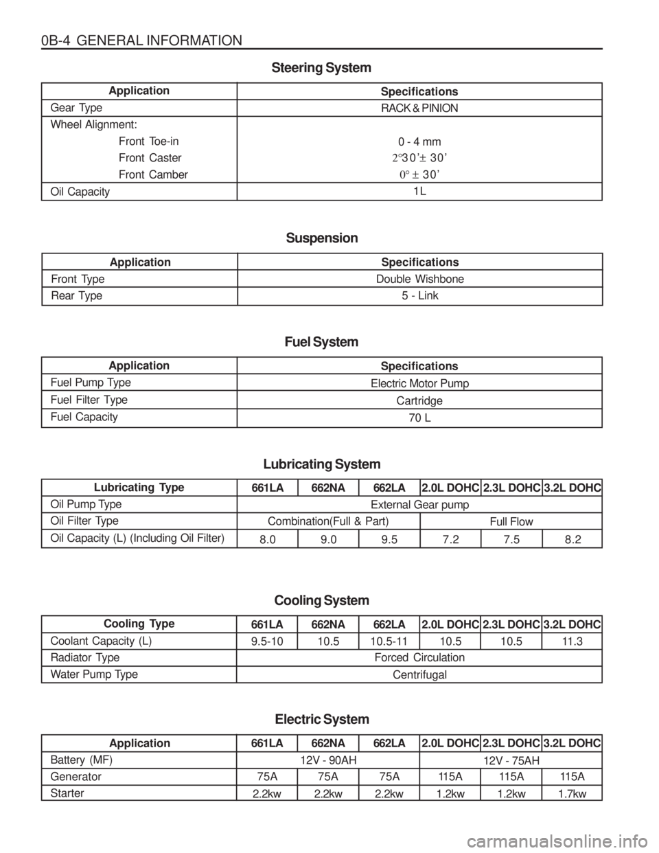
0B-4 GENERAL INFORMATIONSpecifications RACK & PINION0 - 4 mm
2° 30’ ± 30’
0° ± 30’
1L
Application
Gear TypeWheel Alignment: Front Toe-inFront CasterFront Camber
Oil Capacity
Steering System
Application
Front Type
Rear Type
Suspension
Specifications
Double Wishbone
5 - Link
Application
Fuel Pump Type
Fuel Filter TypeFuel Capacity
Specifications
Electric Motor Pump Cartridge70 L
Fuel System
Lubricating Type
Oil Pump Type
Oil Filter Type Oil Capacity (L) (Including Oil Filter)
Lubricating System
661LA
8.0662NA 9.0 662LA
9.5 2.0L DOHC
7.2 2.3L DOHC
7.5 3.2L DOHC
8.2
External Gear pump
Combination(Full & Part) Full Flow
Cooling Type
Coolant Capacity (L)
Radiator Type
Water Pump Type
Cooling System
661LA 9.5-10662NA 10.5 662LA
10.5-11 2.0L DOHC
10.5 2.3L DOHC
10.5 3.2L DOHC
11.3
Forced Circulation
Centrifugal
Application
Battery (MF) GeneratorStarter
Electric System
661LA
75A
2.2kw662NA
75A
2.2kw 662LA
75A
2.2kw 2.0L DOHC
11 5 A
1.2kw 2.3L DOHC
115A
1.2kw 3.2L DOHC
115A
1.7kw
12V - 90AH12V - 75AH
Page 32 of 1574
GENERAL ENGINE INFORMATION 1A1-13
GENERAL INFORMATION
CLEANLINESS AND CARE An automobile engine is a combination of many machined, honed, polished and lapped surfaces withtolerances that are measured in the ten-thousanths ofan inch. When any internal engine parts are serviced,care and cleanliness are important. A liberal coating of enigne oil should be applied to friction areas during
assembly, to protect and lubricate the surfaces on initialoperation. Proper cleaning and protection of machinedsurfaces and friction areas is part of the repairprocedure. This is considered standard shop practice even if not specifically stated. Whenever valve train components are removed for
service, they should be kept in order. They should beinstalled in the same locations, and with the same matingsurfaces, as when they were removed. Battery cables should be disconnected before any majorwork is performed on the engine. Failure to disconnectcables may result in damage to wire harness or other electrical parts. ON-ENGINE SERVICE Caution: Disconnect the negative battery cable before removing or installing any electrical unit, or when a tool or equipment could easily come in contact with exposed electrical terminals.Disconnecting this cable will help prevent personalinjury and damage to the vehicle. The ignition mustalso be in LOCK unless otherwise noted. Notice:
Any time the air cleaner is removed, the intake
opening should be covered. This will protect against accidental entrance of foreign material, which could follow the intake passage into the cylinder and cause extensive damage when the engine is started.
Page 37 of 1574
SECTION 1B1
M162 ENGINE MECHANICAL
CAUTION: Disconnect the negative battery cable before removing or installing any electrical unit or when a tool or equipment could easily come in contact with exposed electrical terminals. Disconnecting this cable will help prevent personal injury and damage to the vehicle. The ignition must also be in LOCK unless otherwisenoted.
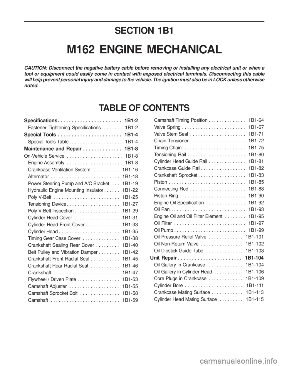
Specifications . . . . . . . . . . . . . . . . . . . . . . . 1B1-2Fastener Tightening Specifications . . . . . . . . 1B1-2
Special Tools . . . . . . . . . . . . . . . . . . . . . . . 1B1-4 Special Tools Table . . . . . . . . . . . . . . . . . . . . 1B1-4
Maintenance and Repair . . . . . . . . . . . . . . 1B1-8
On-Vehicle Service . . . . . . . . . . . . . . . . . . . . . 1B1-8
Engine Assembly . . . . . . . . . . . . . . . . . . . . . 1B1-8
Crankcase Ventilation System . . . . . . . . . . 1B1-16
Alternator . . . . . . . . . . . . . . . . . . . . . . . . . . 1B1-18
Power Steering Pump and A/C Bracket . . . 1B1-19
Hydraulic Engine Mounting Insulator . . . . . . 1B1-22
Poly V-Belt . . . . . . . . . . . . . . . . . . . . . . . . . 1B1-25
Tensioning Device . . . . . . . . . . . . . . . . . . . . 1B1-27
Poly V-Belt Inspection . . . . . . . . . . . . . . . . . 1B1-29
Cylinder Head Cover . . . . . . . . . . . . . . . . . 1B1-31
Cylinder Head Front Cover . . . . . . . . . . . . . 1B1-33
Cylinder Head . . . . . . . . . . . . . . . . . . . . . . . 1B1-35
Timing Gear Case Cover . . . . . . . . . . . . . . 1B1-38
Crankshaft Sealing Rear Cover . . . . . . . . . 1B1-40
Belt Pulley and Vibration Damper . . . . . . . . 1B1-42
Crankshaft Front Radial Seal . . . . . . . . . . . 1B1-45
Crankshaft Rear Radial Seal . . . . . . . . . . . 1B1-46
Crankshaft . . . . . . . . . . . . . . . . . . . . . . . . . 1B1-47
Flywheel / Driven Plate . . . . . . . . . . . . . . . . 1B1-53
Camshaft Adjuster . . . . . . . . . . . . . . . . . . . 1B1-55
Camshaft Sprocket Bolt . . . . . . . . . . . . . . . 1B1-58
Camshaft . . . . . . . . . . . . . . . . . . . . . . . . . . 1B1-59
TABLE OF CONTENTS
Camshaft Timing Position . . . . . . . . . . . . . . 1B1-64
Valve Spring . . . . . . . . . . . . . . . . . . . . . . . . 1B1-67
Valve Stem Seal . . . . . . . . . . . . . . . . . . . . . 1B1-71
Chain Tensioner . . . . . . . . . . . . . . . . . . . . . 1B1-72
Timing Chain . . . . . . . . . . . . . . . . . . . . . . . . 1B1-75
Tensioning Rail . . . . . . . . . . . . . . . . . . . . . . 1B1-80
Cylinder Head Guide Rail . . . . . . . . . . . . . . 1B1-81
Crankcase Guide Rail . . . . . . . . . . . . . . . . . 1B1-82
Crankshaft Sprocket . . . . . . . . . . . . . . . . . . 1B1-83
Piston . . . . . . . . . . . . . . . . . . . . . . . . . . . . . 1B1-85
Connecting Rod . . . . . . . . . . . . . . . . . . . . . 1B1-88
Piston Ring . . . . . . . . . . . . . . . . . . . . . . . . . 1B1-90
Engine Oil Specification . . . . . . . . . . . . . . . 1B1-92
Oil Pan . . . . . . . . . . . . . . . . . . . . . . . . . . . . 1B1-93
Engine Oil and Oil Filter Element . . . . . . . . 1B1-95
Oil Filter . . . . . . . . . . . . . . . . . . . . . . . . . . . 1B1-97
Oil Pump . . . . . . . . . . . . . . . . . . . . . . . . . . . 1B1-99
Oil Pressure Relief Valve . . . . . . . . . . . . . 1B1-101
Oil Non-Return Valve . . . . . . . . . . . . . . . . 1B1-102
Oil Dipstick Guide Tube . . . . . . . . . . . . . . 1B1-103
Unit Repair . . . . . . . . . . . . . . . . . . . . . . . 1B1-104 Oil Gallery in Crankcase . . . . . . . . . . . . . . 1B1-104
Oil Gallery in Cylinder Head . . . . . . . . . . . 1B1-106
Core Plugs in Crankcase . . . . . . . . . . . . . 1B1-109
Cylinder Bore . . . . . . . . . . . . . . . . . . . . . . 1B1-111
Crankcase Mating Surface . . . . . . . . . . . . 1B1-113
Cylinder Head Mating Surface . . . . . . . . . 1B1-115
Page 129 of 1574

M162 ENGINE MECHANICAL 1B1-93
OIL PAN
1 Gasket ................................................... Replace
2 Bolt (M6 x 22, 6 pieces)............................ 10 Nm
3 Drain Plug (M6 x 20) ................................. 25 Nm
4 Bolt (M6 x 20, 22 pieces) .......................... 10 Nm 5 Bolt (M6 x 85)
............................................ 10 Nm
6 Bolt (M8 x 40) ............................................ 25 Nm
7 Bolt (M10) ................................................. 40 Nm
8 Oil Pan
Removal & Installation Procedure
1. Remove the drain plug and drain the oil completely.
2. Disconnect the electric connector from oil level switch.
3. Unscrew the bolts (10) for oil level switch and check the O- ring (11) for wear or damage. And replace it if necessary.
4. Unscrew the bolts and remove the oil pan and gasket.
NoticeArrange the bolts according to each size.
5. Clean the inside of oil pan and sealing surface, then apply the sealant.
6. Replace the gasket with new one.
7. Install the oil pan with gasket, and tighten each bolt in specified torque.
8. Check for oil leaks while running the engine.
M8 X 40, 4 pieces M6 X 85, 3 piecesM6 X 35, 3 piecesM6 X 20, 28 pieces
the rest
Page 153 of 1574
SECTION 1B2
M161 ENGINE MECHANICAL
CAUTION: Disconnect the negative battery cable before removing or installing any electrical unit or when a tool or equipment could easily come in contact with exposed electrical terminals. Disconnecting this cable will help prevent personal injury and damage to the vehicle. The ignition must also be in LOCK unless otherwisenoted.
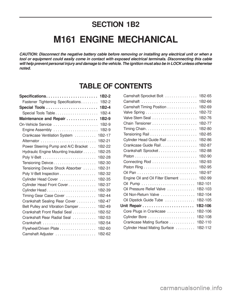
Specifications . . . . . . . . . . . . . . . . . . . . . . . 1B2-2Fastener Tightening Specifications . . . . . . . . 1B2-2
Special Tools . . . . . . . . . . . . . . . . . . . . . . . 1B2-4 Special Tools Table . . . . . . . . . . . . . . . . . . . . 1B2-4
Maintenance and Repair . . . . . . . . . . . . . . 1B2-9
On-Vehicle Service . . . . . . . . . . . . . . . . . . . . . 1B2-9
Engine Assembly . . . . . . . . . . . . . . . . . . . . . 1B2-9
Crankcase Ventilation System . . . . . . . . . . 1B2-17
Alternator . . . . . . . . . . . . . . . . . . . . . . . . . . 1B2-21
Power Steering Pump and A/C Bracket . . . 1B2-22
Hydraulic Engine Mounting Insulator . . . . . . 1B2-25
Poly V-Belt . . . . . . . . . . . . . . . . . . . . . . . . . 1B2-28
Tensioning Deivce . . . . . . . . . . . . . . . . . . . . 1B2-30
Tensioning Device Shock Absorber . . . . . . 1B2-31
Poly V-Belt Inspection . . . . . . . . . . . . . . . . . 1B2-32
Cylinder Head Cover . . . . . . . . . . . . . . . . . 1B2-35
Cylinder Head Front Cover . . . . . . . . . . . . . 1B2-37
Cylinder Head . . . . . . . . . . . . . . . . . . . . . . . 1B2-39
Timing Gear Case Cover . . . . . . . . . . . . . . 1B2-44
Crankshaft Sealing Rear Cover . . . . . . . . . 1B2-47
Belt Pulley and Vibration Damper . . . . . . . . 1B2-49
Crankshaft Front Radial Seal . . . . . . . . . . . 1B2-52
Crankshaft Rear Radial Seal . . . . . . . . . . . 1B2-53
Crankshaft . . . . . . . . . . . . . . . . . . . . . . . . . 1B2-54
Flywheel/Driven Plate . . . . . . . . . . . . . . . . . 1B2-60
Camshaft Adjuster . . . . . . . . . . . . . . . . . . . 1B2-62
TABLE OF CONTENTS
Camshaft Sprocket Bolt . . . . . . . . . . . . . . . 1B2-65
Camshaft . . . . . . . . . . . . . . . . . . . . . . . . . . 1B2-66
Camshaft Timing Position . . . . . . . . . . . . . . 1B2-69
Valve Spring . . . . . . . . . . . . . . . . . . . . . . . . 1B2-72
Valve Stem Seal . . . . . . . . . . . . . . . . . . . . . 1B2-76
Chain Tensioner . . . . . . . . . . . . . . . . . . . . . 1B2-77
Timing Chain . . . . . . . . . . . . . . . . . . . . . . . . 1B2-80
Tensioning Rail . . . . . . . . . . . . . . . . . . . . . . 1B2-85
Cylinder Head Guide Rail . . . . . . . . . . . . . . 1B2-86
Crankcase Guide Rail . . . . . . . . . . . . . . . . . 1B2-87
Crankshaft Sprocket . . . . . . . . . . . . . . . . . . 1B2-88
Piston . . . . . . . . . . . . . . . . . . . . . . . . . . . . . 1B2-90
Connecting Rod . . . . . . . . . . . . . . . . . . . . . 1B2-93
Piston Ring . . . . . . . . . . . . . . . . . . . . . . . . . 1B2-95
Oil Pan . . . . . . . . . . . . . . . . . . . . . . . . . . . . 1B2-97
Engine Oil and Oil Filter Element . . . . . . . . 1B2-99
Oil Pump . . . . . . . . . . . . . . . . . . . . . . . . . 1B2-101
Oil Pressure Relief Valve . . . . . . . . . . . . . 1B2-103
Oil Non-Return Valve . . . . . . . . . . . . . . . . 1B2-104
Oil Dipstick Guide Tube . . . . . . . . . . . . . . 1B2-105
Unit Repair . . . . . . . . . . . . . . . . . . . . . . . 1B2-106 Core Plugs in Crankcase . . . . . . . . . . . . . 1B2-106
Cylinder Bore . . . . . . . . . . . . . . . . . . . . . . 1B2-108
Crankcase Mating Surface . . . . . . . . . . . . 1B2-110
Cylinder Head Mating Surface . . . . . . . . . 1B2-112
Page 266 of 1574
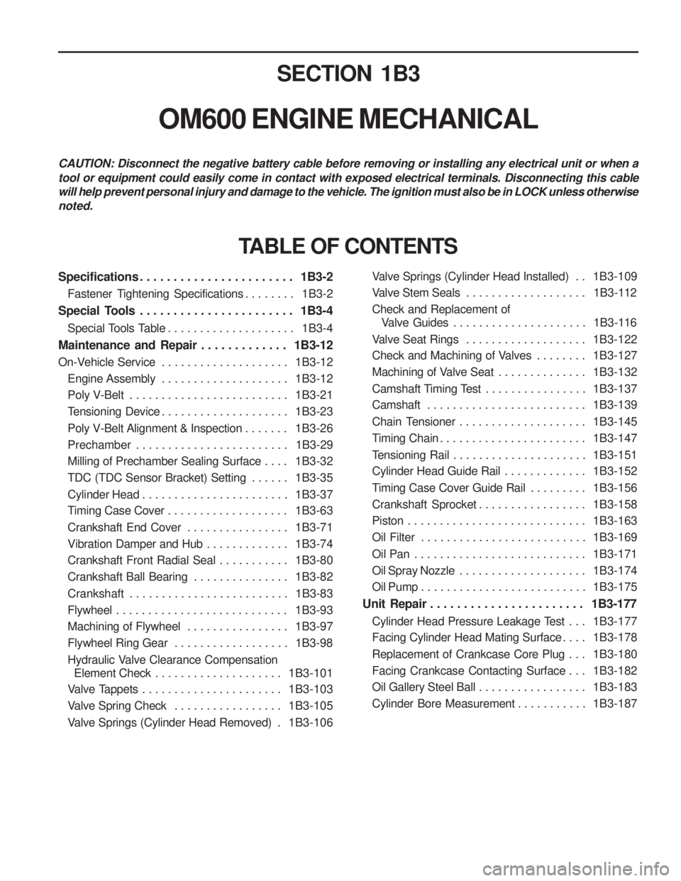
SECTION 1B3
OM600 ENGINE MECHANICAL
CAUTION: Disconnect the negative battery cable before removing or installing any electrical unit or when a tool or equipment could easily come in contact with exposed electrical terminals. Disconnecting this cable will help prevent personal injury and damage to the vehicle. The ignition must also be in LOCK unless otherwisenoted.
Specifications . . . . . . . . . . . . . . . . . . . . . . . 1B3-2Fastener Tightening Specifications . . . . . . . . 1B3-2
Special Tools . . . . . . . . . . . . . . . . . . . . . . . 1B3-4 Special Tools Table . . . . . . . . . . . . . . . . . . . . 1B3-4
Maintenance and Repair . . . . . . . . . . . . . 1B3-12
On-Vehicle Service . . . . . . . . . . . . . . . . . . . . 1B3-12
Engine Assembly . . . . . . . . . . . . . . . . . . . . 1B3-12
Poly V-Belt . . . . . . . . . . . . . . . . . . . . . . . . . 1B3-21
Tensioning Device . . . . . . . . . . . . . . . . . . . . 1B3-23
Poly V-Belt Alignment & Inspection . . . . . . . 1B3-26
Prechamber . . . . . . . . . . . . . . . . . . . . . . . . 1B3-29
Milling of Prechamber Sealing Surface . . . . 1B3-32
TDC (TDC Sensor Bracket) Setting . . . . . . 1B3-35
Cylinder Head . . . . . . . . . . . . . . . . . . . . . . . 1B3-37
Timing Case Cover . . . . . . . . . . . . . . . . . . . 1B3-63
Crankshaft End Cover . . . . . . . . . . . . . . . . 1B3-71
Vibration Damper and Hub . . . . . . . . . . . . . 1B3-74
Crankshaft Front Radial Seal . . . . . . . . . . . 1B3-80
Crankshaft Ball Bearing . . . . . . . . . . . . . . . 1B3-82
Crankshaft . . . . . . . . . . . . . . . . . . . . . . . . . 1B3-83
Flywheel . . . . . . . . . . . . . . . . . . . . . . . . . . . 1B3-93
Machining of Flywheel . . . . . . . . . . . . . . . . 1B3-97
Flywheel Ring Gear . . . . . . . . . . . . . . . . . . 1B3-98
Hydraulic Valve Clearance Compensation
Element Check . . . . . . . . . . . . . . . . . . . . 1B3-101
Valve Tappets . . . . . . . . . . . . . . . . . . . . . . 1B3-103
Valve Spring Check . . . . . . . . . . . . . . . . . 1B3-105
Valve Springs (Cylinder Head Removed) . 1B3-106
TABLE OF CONTENTS
Valve Springs (Cylinder Head Installed) . . 1B3-109
Valve Stem Seals . . . . . . . . . . . . . . . . . . . 1B3-112
Check and Replacement of Valve Guides . . . . . . . . . . . . . . . . . . . . . 1B3-116
Valve Seat Rings . . . . . . . . . . . . . . . . . . . 1B3-122
Check and Machining of Valves . . . . . . . . 1B3-127
Machining of Valve Seat . . . . . . . . . . . . . . 1B3-132
Camshaft Timing Test . . . . . . . . . . . . . . . . 1B3-137
Camshaft . . . . . . . . . . . . . . . . . . . . . . . . . 1B3-139
Chain Tensioner . . . . . . . . . . . . . . . . . . . . 1B3-145
Timing Chain . . . . . . . . . . . . . . . . . . . . . . . 1B3-147
Tensioning Rail . . . . . . . . . . . . . . . . . . . . . 1B3-151
Cylinder Head Guide Rail . . . . . . . . . . . . . 1B3-152
Timing Case Cover Guide Rail . . . . . . . . . 1B3-156
Crankshaft Sprocket . . . . . . . . . . . . . . . . . 1B3-158
Piston . . . . . . . . . . . . . . . . . . . . . . . . . . . . 1B3-163
Oil Filter . . . . . . . . . . . . . . . . . . . . . . . . . . 1B3-169
Oil Pan . . . . . . . . . . . . . . . . . . . . . . . . . . . 1B3-171
Oil Spray Nozzle . . . . . . . . . . . . . . . . . . . . 1B3-174
Oil Pump . . . . . . . . . . . . . . . . . . . . . . . . . . 1B3-175
Unit Repair . . . . . . . . . . . . . . . . . . . . . . . 1B3-177
Cylinder Head Pressure Leakage Test . . . 1B3-177
Facing Cylinder Head Mating Surface . . . . 1B3-178
Replacement of Crankcase Core Plug . . . 1B3-180
Facing Crankcase Contacting Surface . . . 1B3-182
Oil Gallery Steel Ball . . . . . . . . . . . . . . . . . 1B3-183
Cylinder Bore Measurement . . . . . . . . . . . 1B3-187
Page 388 of 1574
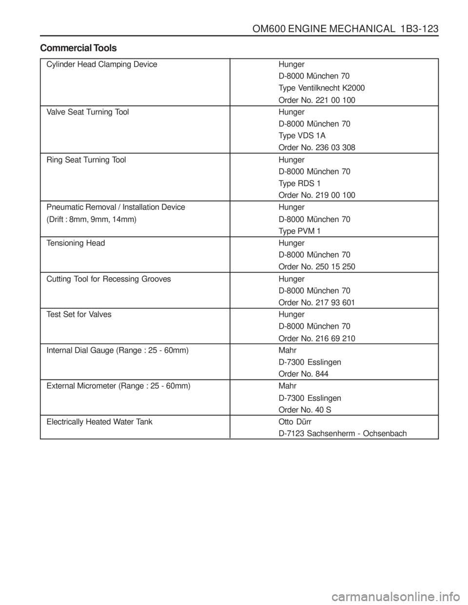
OM600 ENGINE MECHANICAL 1B3-123
Cylinder Head Clamping Device
Valve Seat Turning Tool
Ring Seat Turning Tool Pneumatic Removal / Installation Device (Drift : 8mm, 9mm, 14mm)
Tensioning Head
Cutting Tool for Recessing Grooves
Test Set for Valves Internal Dial Gauge (Range : 25 - 60mm) External Micrometer (Range : 25 - 60mm)
Electrically Heated Water Tank
Commercial ToolsHunger D-8000 M
ünchen 70
Type Ventilknecht K2000 Order No. 221 00 100 HungerD-8000 M ünchen 70
Type VDS 1AOrder No. 236 03 308 Hunger D-8000 M ünchen 70
Type RDS 1Order No. 219 00 100Hunger D-8000 M ünchen 70
Type PVM 1 HungerD-8000 M ünchen 70
Order No. 250 15 250 Hunger D-8000 M ünchen 70
Order No. 217 93 601HungerD-8000 M ünchen 70
Order No. 216 69 210MahrD-7300 EsslingenOrder No. 844Mahr D-7300 Esslingen Order No. 40 SOtto D ürr
D-7123 Sachsenherm - Ochsenbach
Page 452 of 1574
SECTION 1D1
M162 ENGINE COOLING
Specifications . . . . . . . . . . . . . . . . . . . . . . . 1D1-1General Specifications . . . . . . . . . . . . . . . . . 1D1-1
Fastener Tightening Specifications . . . . . . . . 1D1-2
Special Tools . . . . . . . . . . . . . . . . . . . . . . . 1D1-3 Special Tools Table . . . . . . . . . . . . . . . . . . . . 1D1-3
Diagnosis . . . . . . . . . . . . . . . . . . . . . . . . . . 1D1-4 System Leakage Test . . . . . . . . . . . . . . . . . . 1D1-4
Maintenance and Repair . . . . . . . . . . . . . . 1D1-5
On-Vehicle Service . . . . . . . . . . . . . . . . . . . . . 1D1-5Coolant Drain and Fill Up . . . . . . . . . . . . . . .
1D1-5
Coolant Connection Fitting . . . . . . . . . . . . . . 1D1-7
Water Pump . . . . . . . . . . . . . . . . . . . . . . . . . 1D1-8
Thermostat . . . . . . . . . . . . . . . . . . . . . . . . . 1D1-10
Oil Cooler Pipe Line . . . . . . . . . . . . . . . . . . 1D1-11
Cooling Fan and Viscous Clutch . . . . . . . . . 1D1-12
Cooling Fan Shroud . . . . . . . . . . . . . . . . . . 1D1-14
Radiator . . . . . . . . . . . . . . . . . . . . . . . . . . . 1D1-15
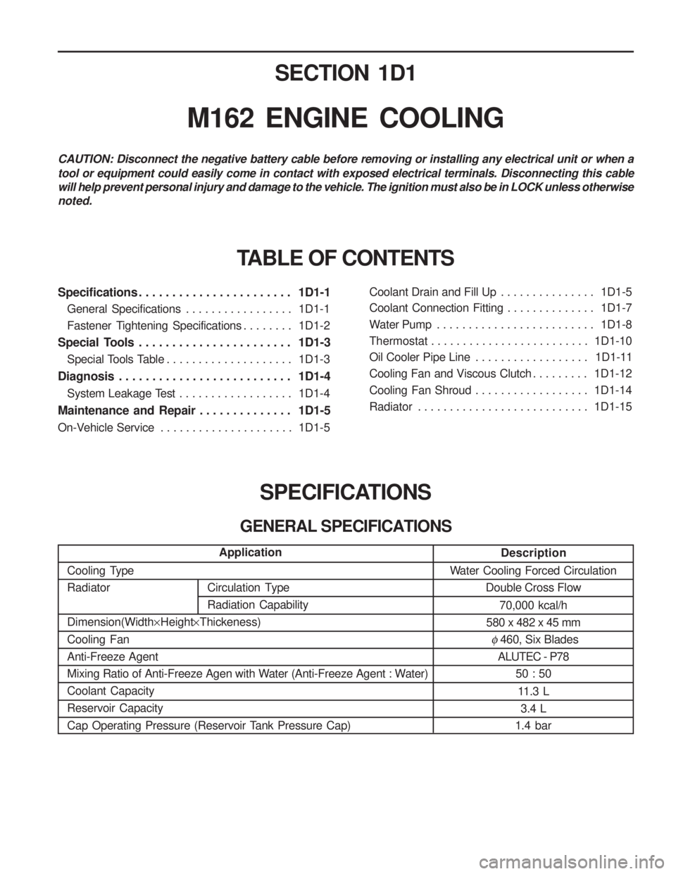
SPECIFICATIONS
GENERAL SPECIFICATIONS
CAUTION: Disconnect the negative battery cable before removing or installing any electrical unit or when a tool or equipment could easily come in contact with exposed electrical terminals. Disconnecting this cable will help prevent personal injury and damage to the vehicle. The ignition must also be in LOCK unless otherwisenoted.
TABLE OF CONTENTS
Description
Water Cooling Forced Circulation Double Cross Flow
70,000 kcal/h
580 x 482 x 45 mm
� 460, Six Blades
ALUTEC - P78
50 : 50
11.3 L 3.4 L
1.4 bar
Application
Cooling Type Radiator Dimension(Width ×Height ×Thickeness)
Cooling Fan Anti-Freeze Agent
Mixing Ratio of Anti-Freeze Agen with Water (Anti-Freeze Agent : Water)Coolant CapacityReservoir Capacity
Cap Operating Pressure (Reservoir Tank Pressure Cap)
Circulation Type Radiation Capability
Page 468 of 1574
Circulation Type RadiationCapabilitySECTION 1D2
M161 ENGINE COOLING
Specifications . . . . . . . . . . . . . . . . . . . . . . . 1D2-1
General Specifications . . . . . . . . . . . . . . . . . 1D2-1
Fastener Tightening Specifications . . . . . . . . 1D2-2
Special Tools . . . . . . . . . . . . . . . . . . . . . . . 1D2-3
Special Tools Table . . . . . . . . . . . . . . . . . . . . 1D2-3
Diagnosis . . . . . . . . . . . . . . . . . . . . . . . . . . 1D2-4 System Leakage Test . . . . . . . . . . . . . . . . . . 1D2-4
Maintenance and Repair . . . . . . . . . . . . . . 1D2-5
On-Vehicle Service . . . . . . . . . . . . . . . . . . . . . 1D2-5Coolant Drain and Fill Up . . . . . . . . . . . . . . .
1D2-5
Cooling Fan and Viscous Clutch . . . . . . . . . . 1D2-7
Coolant Pump . . . . . . . . . . . . . . . . . . . . . . . . 1D2-9
Thermostat . . . . . . . . . . . . . . . . . . . . . . . . . 1D2-11
Thermostat Housing Assembly . . . . . . . . . . 1D2-12
Removal and Installation of Cooling Fan Shroud . . . . . . . . . . . . . . . . . . . . . . . 1D2-14
Removal and Installation of Radiator . . . . . 1D2-15
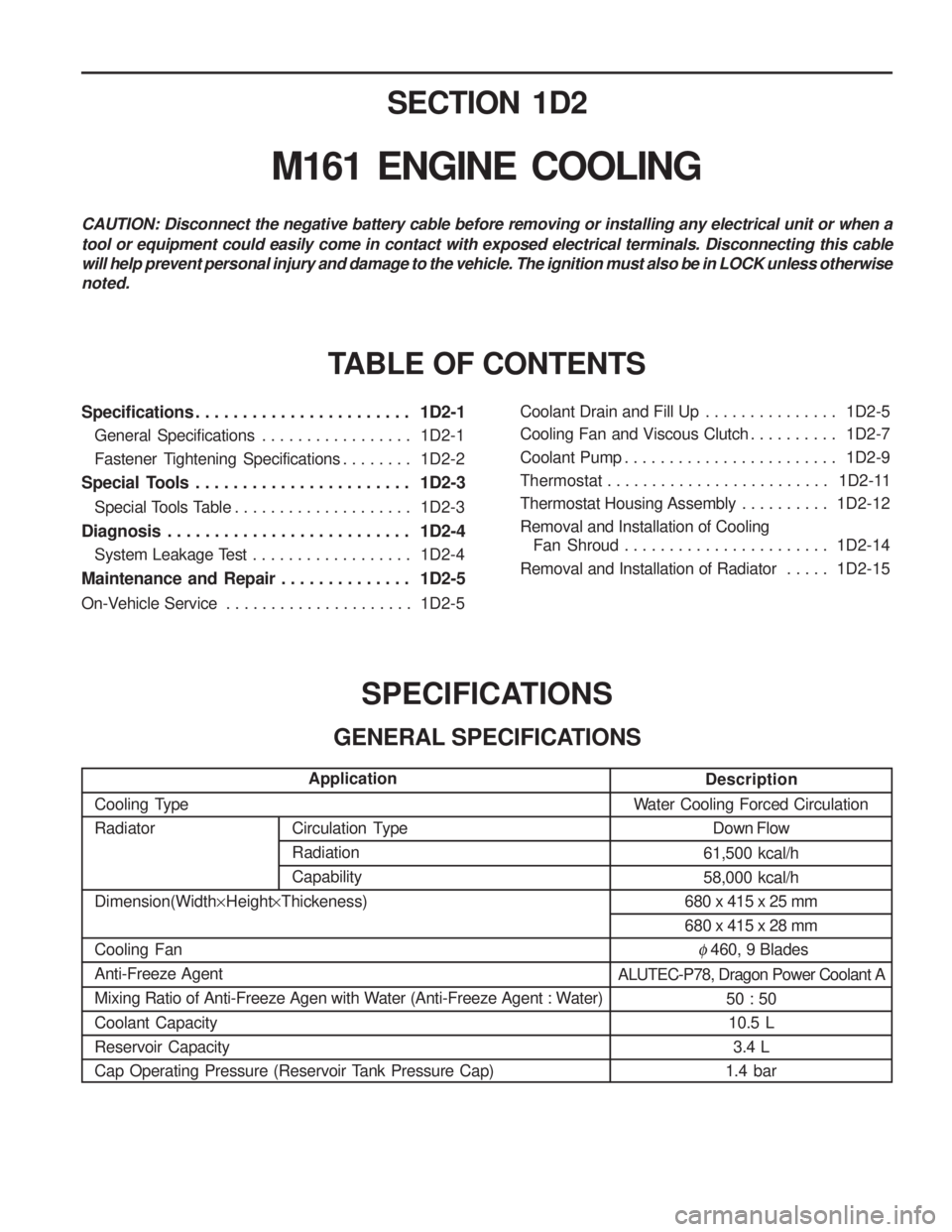
SPECIFICATIONS
GENERAL SPECIFICATIONS
CAUTION: Disconnect the negative battery cable before removing or installing any electrical unit or when a tool or equipment could easily come in contact with exposed electrical terminals. Disconnecting this cable will help prevent personal injury and damage to the vehicle. The ignition must also be in LOCK unless otherwisenoted.
TABLE OF CONTENTS
Description
Water Cooling Forced Circulation Down Flow
61,500 kcal/h 58,000 kcal/h
680 x 415 x 25 mm680 x 415 x 28 mm
� 460, 9 Blades
ALUTEC-P78, Dragon Power Coolant A 50 : 5010.5 L 3.4 L
1.4 bar
Application
Cooling TypeRadiator Dimension(Width ×Height ×Thickeness)
Cooling Fan Anti-Freeze Agent
Mixing Ratio of Anti-Freeze Agen with Water (Anti-Freeze Agent : Water) Coolant Capacity Reservoir Capacity
Cap Operating Pressure (Reservoir Tank Pressure Cap)
Page 484 of 1574
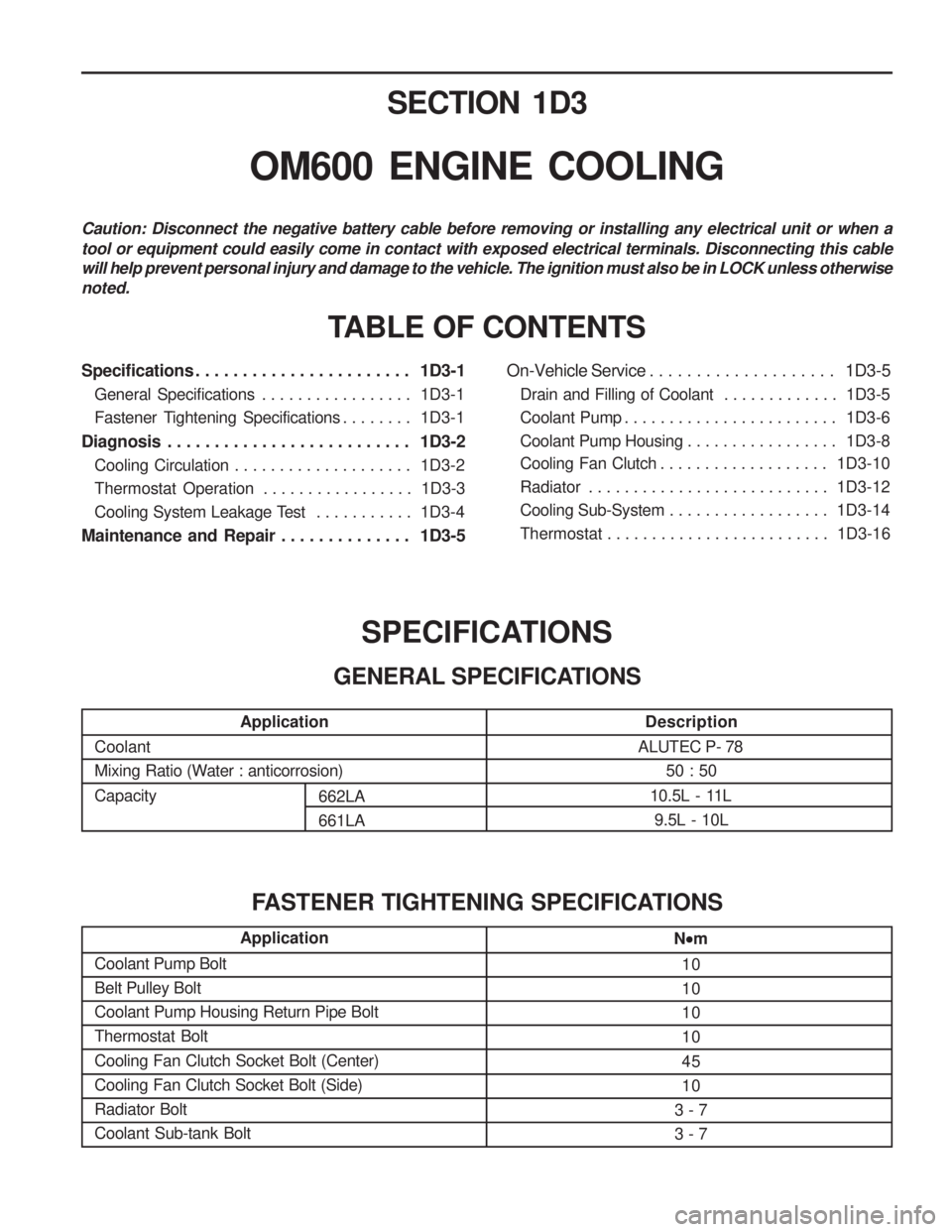
SECTION 1D3
OM600 ENGINE COOLING
Specifications . . . . . . . . . . . . . . . . . . . . . . . 1D3-1General Specifications . . . . . . . . . . . . . . . . . 1D3-1
Fastener Tightening Specifications . . . . . . . . 1D3-1
Diagnosis . . . . . . . . . . . . . . . . . . . . . . . . . . 1D3-2 Cooling Circulation . . . . . . . . . . . . . . . . . . . . 1D3-2
Thermostat Operation . . . . . . . . . . . . . . . . . 1D3-3
Cooling System Leakage Test . . . . . . . . . . . 1D3-4
Maintenance and Repair . . . . . . . . . . . . . . 1D3-5 On-Vehicle Service . . . . . . . . . . . . . . . . . . . .
1D3-5
Drain and Filling of Coolant . . . . . . . . . . . . . 1D3-5
Coolant Pump . . . . . . . . . . . . . . . . . . . . . . . . 1D3-6
Coolant Pump Housing . . . . . . . . . . . . . . . . . 1D3-8
Cooling Fan Clutch . . . . . . . . . . . . . . . . . . . 1D3-10
Radiator . . . . . . . . . . . . . . . . . . . . . . . . . . . 1D3-12
Cooling Sub-System . . . . . . . . . . . . . . . . . . 1D3-14
Thermostat . . . . . . . . . . . . . . . . . . . . . . . . . 1D3-16
TABLE OF CONTENTS
Caution: Disconnect the negative battery cable before removing or installing any electrical unit or when a tool or equipment could easily come in contact with exposed electrical terminals. Disconnecting this cable will help prevent personal injury and damage to the vehicle. The ignition must also be in LOCK unless otherwisenoted.
Application
Coolant
Mixing Ratio (Water : anticorrosion) Capacity
Description
ALUTEC P- 78 50 : 50
10.5L - 11L 9.5L - 10L
SPECIFICATIONS
GENERAL SPECIFICATIONS
Application
Coolant Pump Bolt Belt Pulley BoltCoolant Pump Housing Return Pipe BoltThermostat Bolt Cooling Fan Clutch Socket Bolt (Center) Cooling Fan Clutch Socket Bolt (Side)Radiator BoltCoolant Sub-tank BoltN
m
10 101010 45 10
3 - 73 - 7
FASTENER TIGHTENING SPECIFICATIONS
662LA 661LA