lights SSANGYONG MUSSO 2003 Service Manual
[x] Cancel search | Manufacturer: SSANGYONG, Model Year: 2003, Model line: MUSSO, Model: SSANGYONG MUSSO 2003Pages: 1574, PDF Size: 26.41 MB
Page 12 of 1574

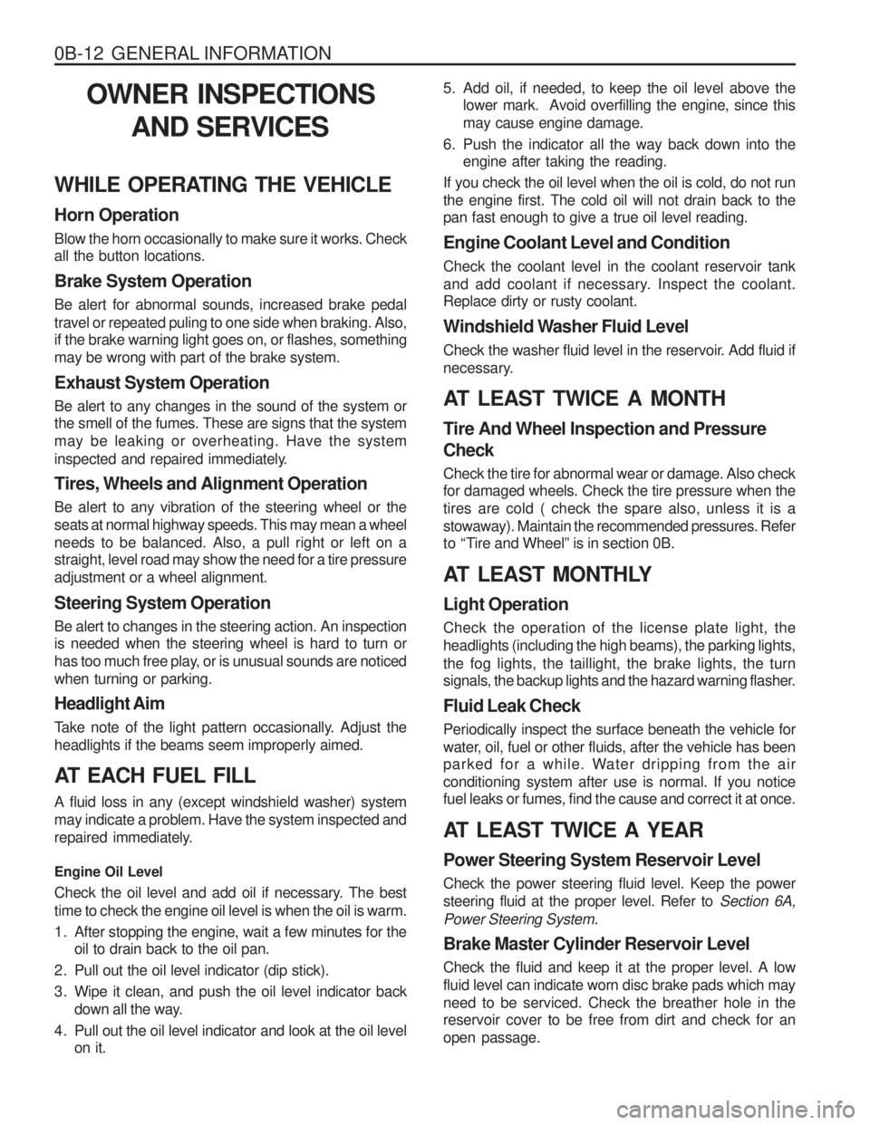
0B-12 GENERAL INFORMATIONOWNER INSPECTIONS AND SERVICES
WHILE OPERATING THE VEHICLE Horn Operation Blow the horn occasionally to make sure it works. Check all the button locations. Brake System Operation Be alert for abnormal sounds, increased brake pedal travel or repeated puling to one side when braking. Also, if the brake warning light goes on, or flashes, something may be wrong with part of the brake system. Exhaust System Operation Be alert to any changes in the sound of the system or the smell of the fumes. These are signs that the system may be leaking or overheating. Have the system
inspected and repaired immediately. Tires, Wheels and Alignment Operation Be alert to any vibration of the steering wheel or the seats at normal highway speeds. This may mean a wheelneeds to be balanced. Also, a pull right or left on a straight, level road may show the need for a tire pressure adjustment or a wheel alignment. Steering System Operation Be alert to changes in the steering action. An inspection is needed when the steering wheel is hard to turn or
has too much free play, or is unusual sounds are noticedwhen turning or parking. Headlight Aim
Take note of the light pattern occasionally. Adjust the headlights if the beams seem improperly aimed.
AT EACH FUEL FILL A fluid loss in any (except windshield washer) system may indicate a problem. Have the system inspected and
repaired immediately. Engine Oil Level
Check the oil level and add oil if necessary. The best time to check the engine oil level is when the oil is warm.
1. After stopping the engine, wait a few minutes for the oil to drain back to the oil pan.
2. Pull out the oil level indicator (dip stick).
3. Wipe it clean, and push the oil level indicator back down all the way.
4. Pull out the oil level indicator and look at the oil level on it. 5. Add oil, if needed, to keep the oil level above the
lower mark. Avoid overfilling the engine, since this may cause engine damage.
6. Push the indicator all the way back down into the engine after taking the reading.
If you check the oil level when the oil is cold, do not runthe engine first. The cold oil will not drain back to the pan fast enough to give a true oil level reading. Engine Coolant Level and Condition Check the coolant level in the coolant reservoir tank
and add coolant if necessary. Inspect the coolant. Replace dirty or rusty coolant.
Windshield Washer Fluid Level
Check the washer fluid level in the reservoir. Add fluid if
necessary.
AT LEAST TWICE A MONTH Tire And Wheel Inspection and Pressure Check Check the tire for abnormal wear or damage. Also check for damaged wheels. Check the tire pressure when the tires are cold ( check the spare also, unless it is astowaway). Maintain the recommended pressures. Refer
to “Tire and Wheel” is in section 0B.
AT LEAST MONTHLY Light Operation Check the operation of the license plate light, the headlights (including the high beams), the parking lights,the fog lights, the taillight, the brake lights, the turn
signals, the backup lights and the hazard warning flasher. Fluid Leak Check Periodically inspect the surface beneath the vehicle for
water, oil, fuel or other fluids, after the vehicle has been
parked for a while. Water dripping from the air conditioning system after use is normal. If you notice fuel leaks or fumes, find the cause and correct it at once.
AT LEAST TWICE A YEAR Power Steering System Reservoir Level Check the power steering fluid level. Keep the power steering fluid at the proper level. Refer to Section 6A,
Power Steering System. Brake Master Cylinder Reservoir Level Check the fluid and keep it at the proper level. A low fluid level can indicate worn disc brake pads which mayneed to be serviced. Check the breather hole in the reservoir cover to be free from dirt and check for an open passage.
Page 648 of 1574

1F3-38 OM600 ENGINE CONTROLS
Tools Required 617 589 08 21 00 Position Sensor
Test Procedure
1. Remove the screw plug (5) and seal (4) and collect oil in a suitable vessel.
2. Install the position sensor (1) into the governor housing of
the injection pump to be the guide pin of the position sensor facing up.
3. Connect the battery terminal of position sensor (1) to positive terminal (+) of battery.
Position Sensor 617 589 08 21 00
4. Rotate the crankshaft by hand (in direction of engine rotation) until the lamp ‘B’ lights up. Rotate the crankshaft carefully
further until both lamps ‘A and B ’ come on. In this position,
check the Rl value on the crankshaft vibration damper. Notice If only lamp ‘A’ lights up, repeat the test and if out of
specification, adjust start of delivery.
Specification A TDC 14° - 16 °
Page 880 of 1574

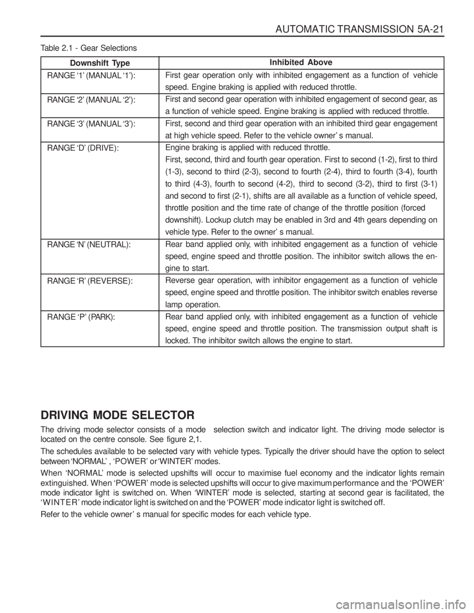
AUTOMATIC TRANSMISSION 5A-21
Downshift Type
RANGE ‘1’ (MANUAL ‘1’):
RANGE ‘2’ (MANUAL ‘2’):
RANGE ‘3’ (MANUAL ‘3’):
RANGE ‘D’ (DRIVE):
RANGE ‘N’ (NEUTRAL):
RANGE ‘R’ (REVERSE):
RANGE ‘P’ (P ARK):Inhibited Above
First gear operation only with inhibited engagement as a function of vehicle speed. Engine braking is applied with reduced throttle.
First and second gear operation with inhibited engagement of second gear, as
a function of vehicle speed. Engine braking is applied with reduced throttle.
First, second and third gear operation with an inhibited third gear engagement
at high vehicle speed. Refer to the vehicle owner’ s manual.Engine braking is applied with reduced throttle.
First, second, third and fourth gear operation. First to second (1-2), first to third
(1-3), second to third (2-3), second to fourth (2-4), third to fourth (3-4), fourth
to third (4-3), fourth to second (4-2), third to second (3-2), third to first (3-1)
and second to first (2-1), shifts are all available as a function of vehicle speed,throttle position and the time rate of change of the throttle position (forced
downshift). Lockup clutch may be enabled in 3rd and 4th gears depending on
vehicle type. Refer to the owner’ s manual.
Rear band applied only, with inhibited engagement as a function of vehicle
speed, engine speed and throttle position. The inhibitor switch allows the en-gine to start.
Reverse gear operation, with inhibitor engagement as a function of vehicle
speed, engine speed and throttle position. The inhibitor switch enables reverse lamp operation.
Rear band applied only, with inhibited engagement as a function of vehicle
speed, engine speed and throttle position. The transmission output shaft is
locked. The inhibitor switch allows the engine to start.
Table 2.1 - Gear Selections DRIVING MODE SELECTOR
The driving mode selector consists of a mode selection switch and indicator light. The driving mode selector is
located on the centre console. See figure 2,1.
The schedules available to be selected vary with vehicle types. Typically the driver should have the option to select
between ‘NORMAL’ , ‘POWER’ or ‘WINTER’ modes.
When ‘NORMAL’ mode is selected upshifts will occur to maximise fuel economy and the indicator lights remain
extinguished. When ‘POWER’ mode is selected upshifts will occur to give maximum performance and the ‘POWER’
mode indicator light is swi tched on. When ‘WINTER’ mode is selected, starting at second gear is facilitated, the
‘WINTER’ mode indicator light is switched on and the ‘POWER’ mode indicator light is switched off.
Refer to the vehicle owner ’ s manual for specific modes for each vehicle type.
Page 1056 of 1574

5D1-4 TRANSFER CASE (PART TIME 4408)SELF-DIAGNOSIS
SYSTEM DESCRIPTION
1. TCCU detects transfer case system malfunctions and indicates malfunctioning part(s) through flashing 4H,4L indicator lights.
Using a service connector, connect it to the diagnosis box in the engine room and read the flashing of the ‘4WD
CHECK ’ indicator light.
The flashing indicator light will show you defective code(s).
2. Identify 7 defective codes after reading the flashing indicator light.
� TCCU
� Shift motor
� Magnetic synchronizer clutch
� Speed sensor
� Hub solenoid
� Selector switch
� Motor position sensor
3. Transfer case system is malfunctioning when: � 4H ,4L indicator lights are remain on after 0.6 second when turning the ignition switch ‘ON ’
� 4H,4L indicator lights are continuously come on during driving.
4. If only 1 part is malfunctioning, ‘4WD CHECK ’ indicator light
will display defective code 3 times continuously.
5. If more then 2 part is malfunctioning, the first malfunctioning part will be displayed 3 times and following malfunctioningparts will be displayed .
6. To read defective code, connect the service connector and turn the ignition switch 'ON'.
7. After repairing, eliminate the defective code stored in the TCCU. NoticeBefore replacing the malfunction parts with defective code, check the wires and connectors for proper condition.
Page 1089 of 1574

TRANSFER CASE (PART TIME 4408) 5D1-37
Inspection and Repair
1. 4H and 4L indicator light inspection� When turn the ignition switch to "ON" position, 4H and
4L indicator light will turn on for 0.6 second and will turn
off immediately.
Notice
If indicator light does not turn on, check bulb, wiring harness and TCCU.
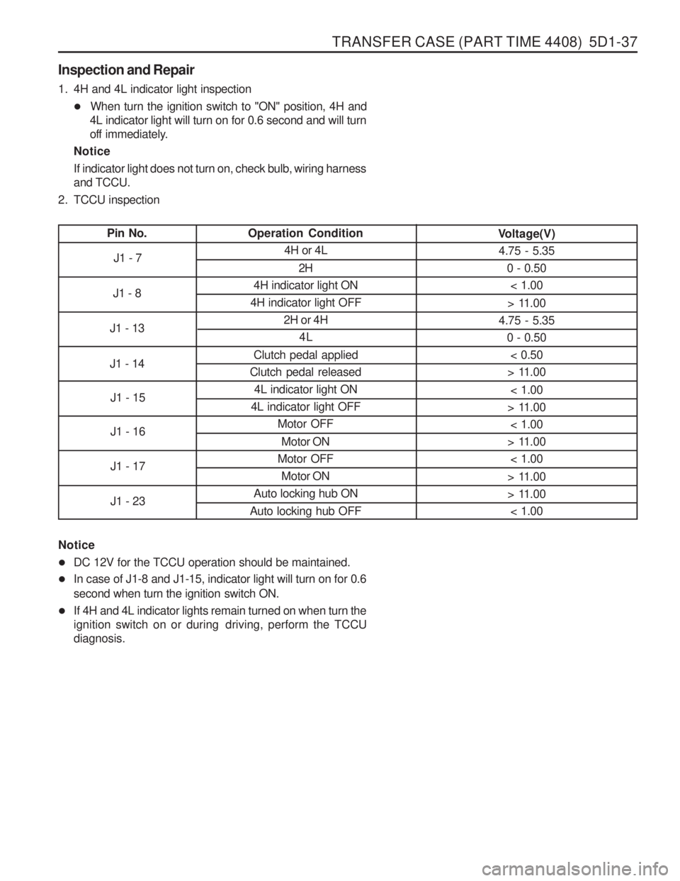
2. TCCU inspection
Pin No. Operation Condition
4H or 4L
2H
4H indicator light ON
4H indicator light OFF 2H or 4H4L
Clutch pedal applied
Clutch pedal released 4L indicator light ON
4L indicator light OFF Motor OFF
Motor ON
Motor OFF Motor ON
Auto locking hub ON
Auto locking hub OFF Voltage(V)
4.75 - 5.35
0 - 0.50< 1.00
> 11.00
4.75 - 5.35 0 - 0.50
< 0.50
> 11.00
< 1.00
> 11.00 < 1.00
> 11.00 < 1.00
> 11.00
> 11.00 < 1.00
J1 - 7
J1 - 8
J1 - 13 J1 - 14 J1 - 15 J1 - 16 J1 - 17 J1 - 23
Notice � DC 12V for the TCCU operation should be maintained.
� In case of J1-8 and J1-15, indicator light will turn on for 0.6
second when turn the ignition switch ON.
� If 4H and 4L indicator lights remain turned on when turn the
ignition switch on or during driving, perform the TCCUdiagnosis.
Page 1174 of 1574

7D-18 FATC-HAVC Sun load Sensor Sun load sensor is a photo diode that detects lights. Resistance of diode can be measured as current by using multimeteraccording to increasing sun loads.
1. Check current on the circuits between the sun load sensorand the airconditioner control unit.
2. Turn the ignition switch to ON position and check that voltage between No. 13a terminal of the sun load sensor and vehicle
ground is 5V.
3. Measure current between No. 13a terminal of the sun load sensor and No. 11 terminal of the control unit and check it isas shown in the below graph.
4. If current value is out of specification, replace the sun load sensor.
Page 1501 of 1574

5-136 ELECTRICAL WIRING DIAGRAMS
28. REAR FOG LAMP CIRCUITC101
W/H MAIN
Main - Engine Main - EngineMain - FloorMain - Floor Floor - Tail Gate Floor - Tail GateMainTail GateMain Main Floor
C101 (21Pin, Colorless)C103 (21Pin, White)C301 (20Pin, White)C302 (16Pin, White) C402 (2Pin, Colorless) C403 (6Pin, Colorless)S203 (Gray)S401 (Gray)G201 G203 G302
b. CONNECTOR IDENTIFICATION SYMBOL & PIN NUMBER POSITION
a. CONNECTOR INFORMATION
CONNECTOR(NUMBER)
CONNECTING. WIRING HARNESSCONNECTOR POSITION
Inside The Engine Room Fuse Block Inside The Engine Room Fuse Block Beside The I/P Relay BlockBeside The I/P Relay BlockBehind The Left LampBehind The Left Lamp Under Right The Audio Behind The Left The LampRight The I/P Fuse BlockUpper The ECMBeside The Left Rear Speaker
C301
W/H MAIN
12345 6789
10 11 12 13 14 15 16 17 18 19 20
C302
W/H MAIN
12 34
5678910
11 12 13 14 15 16
MULTI-FUNCTION SWITCH
C1C2
C3 C4
B1 B2 B3 B4
B5 B6 B7 B8 B9B10
A1 A2 A3 A4 A5 A6
A7 A8 A9A10 A11 A12 A13 A1412
3456
REAR FOG SWITCH
C103
W/H MAIN
2112
3456
C402
W/H FLOOR C403
W/H FLOOR
30 58 BAT+ILL
31 GND
G203
G302
G201
B
RL
B7
B9
B7 B9 E
f11
Rear Fog
Relay
MultiFunctionSwitch(LightSwitch) Rear Fog LampSwtich Rear
FogLamp
Indicator
Switch
ILL
Lamp
10A
C101
BrR GW GW
31 30 R R GW GW
2
C301
10
C302
5 C30210
C403C1015 10A
C101
C203
GW GW GW
LH RHR R B B
B
5
62
R
R
87
LgB
LgW
LgW
R R
LgB
E
15
BB
1 2
12
10 14 11
4
5
1
4
Illumination Relay"5"
"C4"
Multii Function switch
(Head Lamp Switch)
Ef2
C103
80A
E
f8 E
f10
60A
F16 15A1
C302
6
C302
OFF
2
C402
C401
2
9
1
2