roll bar SSANGYONG MUSSO 2003 Service Manual
[x] Cancel search | Manufacturer: SSANGYONG, Model Year: 2003, Model line: MUSSO, Model: SSANGYONG MUSSO 2003Pages: 1574, PDF Size: 26.41 MB
Page 700 of 1574

SUSPENSION DIAGNOSIS 2A-3
DIAGNOSIS
GENERAL DIAGNOSIS
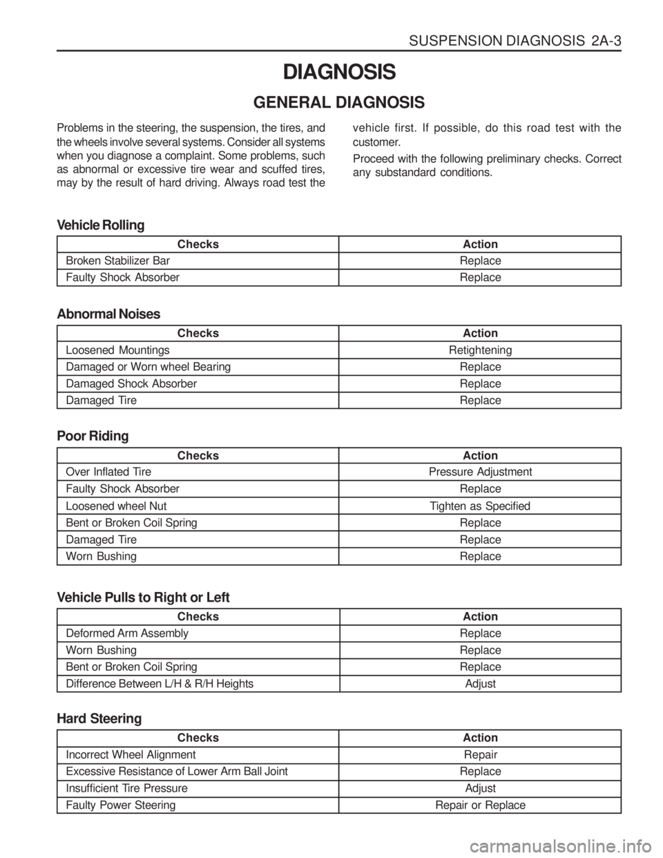
Checks
Loosened Mountings Damaged or Worn wheel BearingDamaged Shock Absorber
Damaged Tire Action
Retightening ReplaceReplaceReplace
Abnormal Noises
Checks
Broken Stabilizer Bar Faulty Shock Absorber Action
ReplaceReplace
Vehicle Rolling
Checks
Over Inflated Tire Faulty Shock Absorber Loosened wheel Nut Bent or Broken Coil Spring
Damaged TireWorn Bushing Action
Pressure Adjustment
Replace
Tighten as Specified ReplaceReplaceReplace
Poor Riding
Problems in the steering, the suspension, the tires, and the wheels involve several systems. Consider all systems when you diagnose a complaint. Some problems, suchas abnormal or excessive tire wear and scuffed tires,may by the result of hard driving. Always road test the
vehicle first. If possible, do this road test with the
customer. Proceed with the following preliminary checks. Correct any substandard conditions.
Checks
Incorrect Wheel Alignment Excessive Resistance of Lower Arm Ball Joint
Insufficient Tire PressureFaulty Power Steering
Action Repair
Replace Adjust
Repair or Replace
Hard Steering
Checks
Deformed Arm Assembly Worn BushingBent or Broken Coil SpringDifference Between L/H & R/H Heights Action
ReplaceReplaceReplace Adjust
Vehicle Pulls to Right or Left
Page 932 of 1574

AUTOMATIC TRANSMISSION 5A-73
Table 6.2.3 - Shift Quality Faults
Action
Check the resistance. Replace the inhibitor
switch as necessary.
Inspect and replace the sensor as necessary.
Inspect and adjust the band as necessary.Inspect and replace the ’0’rings as necessary.
Inspect, repair or replace S5 as necessary.
Inspect, repair or replace S1 or S4 as neces-
sary.
Inspect, repair or replace the BAR as neces-
sary.
Inspect and repair as necessary.
Inspect and clean CCCV.
Inspect, repair or replace as necessary.
Possible Cause
Faulty inhibitor switch.
Faulty throttle position sensor. Incorrect front band adjustment.Damaged front servo piston ’0’rings.
Faulty or damaged variable pressure so- lenoid (S5). Faulty S1 or S4 solenoid. Faulty band apply regulator valve (BAR). Misassembled front servo return spring. Jammed converter clutch control valve(CCCV).Faulty solenoid 7.Symptom
Harsh 1-2 shift stalls when Drive
or Reverse selected Shudder
on Rolldown
Page 952 of 1574

AUTOMATIC TRANSMISSION 5A-93
Valve Body
To disassemble the valve body, proceed as follows.1. Remove the detent spring and retainer plate using a T40 Torx bit.
Notice
Be aware that the manual valve will fall out of the valve body.
2. Take note of the angular relationship of the solenoid terminals to the valve body, then slide the manual valve out of the lower
valve body.
3. Remove the solenoid and valve assembly as follows: � solenoid 1
� solenoid 2
� solenoid 3
� solenoid 4
� solenoid 5
� solenoid 6
4. Place the valve body assembly on the bench with the upper body uppermost.
5. Remove the 24 clamping screws with a No. 30 Ton bit. Separate the upper and lower valve bodies by lifting the upper body and
the separator plate together.
6. Upper body over and place it on the bench with the separator plate uppermost.
7. Lift the separator plate and gaskets from the upper valve body.
8. Remove the five nylon check balls exposed in the valve body.
9. Remove the retainer plate, plug, spring and reverse lockout valve.
10. Remove the two filters (and the large nylon check ball) from the lower valve body. Notice Once the pins are removed, the plates are loose in the valve
body and will drop out when the valve body is turned over.
11. Remove the keeper plates and pins from the 1-2,2-3,3-4, BAR and CAR valves. The pins can be removed with a magnet.
12. Remove the 1-2,2-3 and 3-4 shift valves. Notice The plug is preloaded by the spring and may unexpectedly fall
out of the valve body.
13. Depress the 4-3 sequence valve plug and remove the keeper plate.
14. Remove the plug, valve and spring.
15. Depress the solenoid 5 valve. Remove the keeper pin and remove the valve and spring. Notice The valve is preloaded by the spring and may unexpectedly fall
out of the valve body.
16. Depress the line pressure release valve, remove the keeper pin, disc (if fitted), spring and valve.
17. Drive out the roll pin and remove the spring and ball check valve adjacent to the BAR valve.
Page 1316 of 1574

1A-4 MUSSO-SPORTS
SUPPLEMENT
from vacuum pump
EGR valve
EGR control unit
KAA5A020
KAA5A020
KAA5A020
KAA5A020 EGR COMPONENTS EGR Unit
1. Location: behind passenger's side panel
2. Arrangement: 81-pin connector
3. Integrated self-diagnostic function (Scan-100: not
fixed)
4. Part number For automatic transmission: 28800-07100 For manual transmission: 28800-07000
Vacuum Modulator
1. Location: in front of intake manifold
2. Continuous precise control with the signals from EGR unit (PWM-Pulse With Modulation Control)
3. Rated voltage: 12 V
4. Operating voltage: 8 ~ 16 V
5. Resistance (at 20 °C): 15.4 ± 0.7 �
6. Operating range of vacuum (Duty control)
Vacuum modulator 1: 0 ~ 600 mbar
Vacuum modulator 2: 300 ~ 600 mbar
7. Modulator control
Vacuum modulator 1: for controlling EGR valve
Vacuum modulator 2: for controlling no-load sharp
acceleration (ALDA control)
not used connector
Vacuum modulator 1
(for controlling EGR valve)Vacuum modulator 2
(for controlling ALDA)
from vacuum pump
Vacuum modulator 1
Vacuum modulator 2
Solenoid valve
ALDAIntake
manifold
EGR control unit
Page 1317 of 1574

MUSSO-SPORTS 1A-5
SUPPLEMENT
KAA5A020
KAA5A020
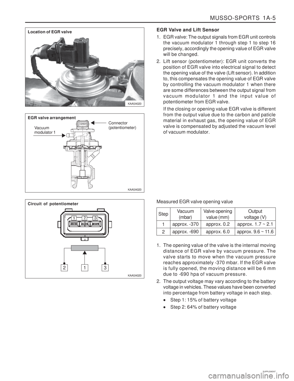
KAA5A020EGR Valve and Lift Sensor
1. EGR valve: The output signals from EGR unit controls
the vacuum modulator 1 through step 1 to step 16 precisely, accordingly the opening value of EGR valvewill be changed.
2. Lift sensor (potentiometer): EGR unit converts the position of EGR valve into electrical signal to detectthe opening value of the valve (Lift sensor). In additionto, this compensates the opening value of EGR valveby controlling the vacuum modulator 1 when thereare some differences between the output signal fromvacuum modulator 1 and the input value ofpotentiometer from EGR valve. If the closing or opening value EGR valve is different from the output value due to the carbon and paticlematerial in exhaust gas, the opening value of EGRvalve is compensated by adjusted the vacuum levelof vacuum modulator.
Measured EGR valve opening value Step 1 2
Vacuum(mbar)
approx. -370 approx. -690 Valve opening
value (mm)
approx. 0.2approx. 6.0 Output
voltage (V)
approx. 1.7 ~ 2.1
approx. 9.6 ~ 11.6
1. The opening value of the valve is the internal moving distance of EGR valve by vacuum pressure. The valve starts to move when the vacuum pressurereaches approximately -370 mbar. If the EGR valveis fully opened, the moving distance will be 6 mmdue to -690 hpa of vacuum pressure.
2. The output voltage may vary according to the battery voltage in vehicles. These values have been convertedinto percentage from battery voltage in each step.
Step 1: 15% of battery voltage
Step 2: 64% of battery voltage
Location of EGR valve EGR valve arrangement
Vacuum modulator 1 Connector (potentiometer)
Circuit of potentiometer
312