suspension SSANGYONG MUSSO 2003 Service Manual
[x] Cancel search | Manufacturer: SSANGYONG, Model Year: 2003, Model line: MUSSO, Model: SSANGYONG MUSSO 2003Pages: 1574, PDF Size: 26.41 MB
Page 4 of 1574
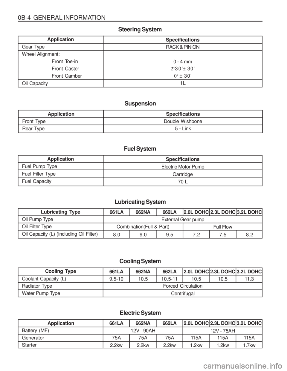
0B-4 GENERAL INFORMATIONSpecifications RACK & PINION0 - 4 mm
2° 30’ ± 30’
0° ± 30’
1L
Application
Gear TypeWheel Alignment: Front Toe-inFront CasterFront Camber
Oil Capacity
Steering System
Application
Front Type
Rear Type
Suspension
Specifications
Double Wishbone
5 - Link
Application
Fuel Pump Type
Fuel Filter TypeFuel Capacity
Specifications
Electric Motor Pump Cartridge70 L
Fuel System
Lubricating Type
Oil Pump Type
Oil Filter Type Oil Capacity (L) (Including Oil Filter)
Lubricating System
661LA
8.0662NA 9.0 662LA
9.5 2.0L DOHC
7.2 2.3L DOHC
7.5 3.2L DOHC
8.2
External Gear pump
Combination(Full & Part) Full Flow
Cooling Type
Coolant Capacity (L)
Radiator Type
Water Pump Type
Cooling System
661LA 9.5-10662NA 10.5 662LA
10.5-11 2.0L DOHC
10.5 2.3L DOHC
10.5 3.2L DOHC
11.3
Forced Circulation
Centrifugal
Application
Battery (MF) GeneratorStarter
Electric System
661LA
75A
2.2kw662NA
75A
2.2kw 662LA
75A
2.2kw 2.0L DOHC
11 5 A
1.2kw 2.3L DOHC
115A
1.2kw 3.2L DOHC
115A
1.7kw
12V - 90AH12V - 75AH
Page 13 of 1574
GENERAL INFORMATION 0B-13
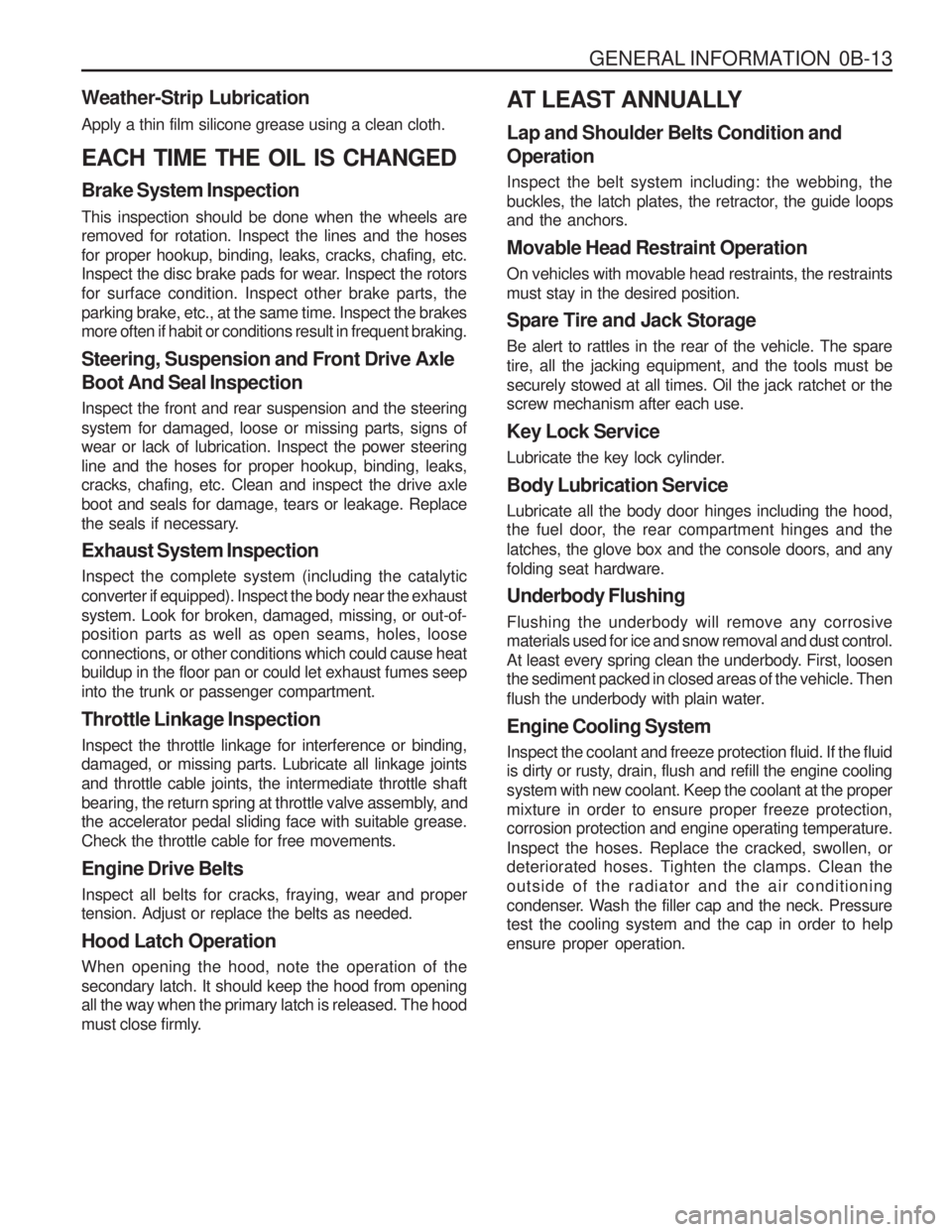
Weather-Strip Lubrication Apply a thin film silicone grease using a clean cloth. EACH TIME THE OIL IS CHANGED Brake System Inspection This inspection should be done when the wheels are removed for rotation. Inspect the lines and the hoses for proper hookup, binding, leaks, cracks, chafing, etc.
Inspect the disc brake pads for wear. Inspect the rotors for surface condition. Inspect other brake parts, theparking brake, etc., at the same time. Inspect the brakes more often if habit or conditions result in frequent braking. Steering, Suspension and Front Drive Axle Boot And Seal Inspection Inspect the front and rear suspension and the steering system for damaged, loose or missing parts, signs of wear or lack of lubrication. Inspect the power steering line and the hoses for proper hookup, binding, leaks, cracks, chafing, etc. Clean and inspect the drive axle boot and seals for damage, tears or leakage. Replace
the seals if necessary. Exhaust System Inspection Inspect the complete system (including the catalytic converter if equipped). Inspect the body near the exhaustsystem. Look for broken, damaged, missing, or out-of- position parts as well as open seams, holes, loose connections, or other conditions which could cause heat buildup in the floor pan or could let exhaust fumes seep into the trunk or passenger compartment. Throttle Linkage Inspection Inspect the throttle linkage for interference or binding, damaged, or missing parts. Lubricate all linkage joints and throttle cable joints, the intermediate throttle shaft
bearing, the return spring at throttle valve assembly, and the accelerator pedal sliding face with suitable grease. Check the throttle cable for free movements. Engine Drive Belts Inspect all belts for cracks, fraying, wear and proper tension. Adjust or replace the belts as needed. Hood Latch Operation When opening the hood, note the operation of the secondary latch. It should keep the hood from opening all the way when the primary latch is released. The hood
must close firmly. AT LEAST ANNUALLY Lap and Shoulder Belts Condition and Operation Inspect the belt system including: the webbing, the
buckles, the latch plates, the retractor, the guide loops and the anchors. Movable Head Restraint Operation On vehicles with movable head restraints, the restraints must stay in the desired position. Spare Tire and Jack Storage Be alert to rattles in the rear of the vehicle. The spare tire, all the jacking equipment, and the tools must besecurely stowed at all times. Oil the jack ratchet or the screw mechanism after each use. Key Lock Service
Lubricate the key lock cylinder. Body Lubrication Service Lubricate all the body door hinges including the hood,
the fuel door, the rear compartment hinges and the latches, the glove box and the console doors, and anyfolding seat hardware. Underbody Flushing Flushing the underbody will remove any corrosive materials used for ice and snow removal and dust control.
At least every spring clean the underbody. First, loosen the sediment packed in closed areas of the vehicle. Then
flush the underbody with plain water. Engine Cooling System Inspect the coolant and freeze protection fluid. If the fluid
is dirty or rusty, drain, flush and refill the engine cooling system with new coolant. Keep the coolant at the propermixture in order to ensure proper freeze protection, corrosion protection and engine operating temperature. Inspect the hoses. Replace the cracked, swollen, or
deteriorated hoses. Tighten the clamps. Clean the outside of the radiator and the air conditioning
condenser. Wash the filler cap and the neck. Pressure test the cooling system and the cap in order to help ensure proper operation.
Page 441 of 1574

OM600 ENGINE MECHANICAL 1B3-177
CYLINDER HEAD PRESSURE LEAKAGE TEST Preceding Work : Removal of the cylinder head Removal of the exhaust manifold Removal of the valve
1 Feed Pipe
2 Bolt
3 Return Connection
4 Gasket ................................................................ Replace
5 Coolant Gallery ................................................... Sealing
6 Pressure Measuring Plate ..................................Completely tight to the cylinder head
7 Cylinder Head .....................................................
Immerse with pressure measuring plate into warm water of approx. 60 °C and pressurize with compressed
airof 2 bar.
Notice If air bubbles are seen, replace the cylinderhead.
Tools Required
115 589 34 63 00 Pressure Measuring Plate 601 589 00 25 00 Suspension Device
UNIT REPAIR
Page 698 of 1574

SECTION 2A
SUSPENSION DIAGNOSIS
TABLE OF CONTENTS
Specifications . . . . . . . . . . . . . . . . . . . . . . . . 2A-1
General Specifications . . . . . . . . . . . . . . . . . . 2A-1
Diagnosis . . . . . . . . . . . . . . . . . . . . . . . . . . . 2A-3
General Diagnosis . . . . . . . . . . . . . . . . . . . . . 2A-3
Input & Output Devices and Damping Force Control Logic . . . . . . . . . . . . . . . . . 2A-5
Input & Output Devices . . . . . . . . . . . . . . . . . . 2A-5
System Layout . . . . . . . . . . . . . . . . . . . . . . . . 2A-5Damping Force Control Logic . . . . . . . . . . . . . 2A-6
Normal Control . . . . . . . . . . . . . . . . . . . . . . . . 2A-6
Self-Diagnosis . . . . . . . . . . . . . . . . . . . . . . . . 2A-7
Actuator Inspection . . . . . . . . . . . . . . . . . . . . . 2A-8
Schematic and Routing Diagrams . . . . . . . . 2A-9
ECS Circuit . . . . . . . . . . . . . . . . . . . . . . . . . . . 2A-9
Self Diagnosis Test . . . . . . . . . . . . . . . . . . 2A-12
Diagnosis Test . . . . . . . . . . . . . . . . . . . . . . . 2A-12
SPECIFICATIONS
GENERAL SPECIFICATIONS
188
Application
Front
3-stage Variable Damping Force Control Type Rear
ECS Control Type
344 - 350
Shock Absorber517 - 523
Max. Length (mm)
245 ± 3
Compressed Length (mm) 102
Stroke (mm)331 ± 3
Page 699 of 1574
2A-2 SUSPENSION DIAGNOSISApplication
Description
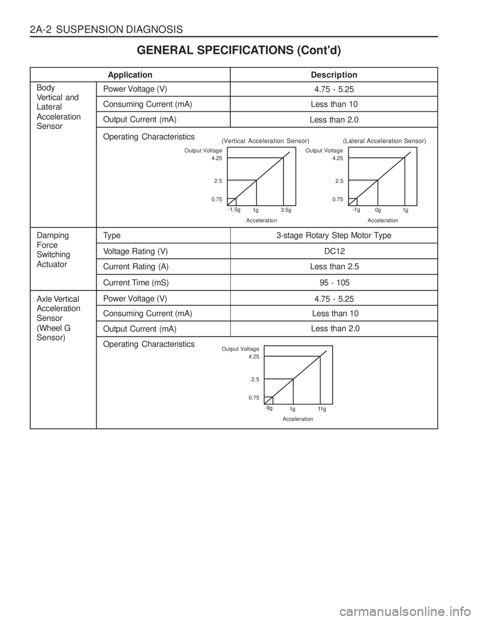
4.75 - 5.25Power Voltage (V)
Axle Vertical Acceleration Sensor(Wheel G Sensor) Less than 10
Consuming Current (mA)
Less than 2.0
Output Current (mA)
Operating Characteristics
Type
Damping Force Switching Actuator3-stage Rotary Step Motor Type
Voltage Rating (V)
DC12
Current Rating (A)
Less than 2.5
Current Time (mS) 95 - 105
4.75 - 5.25Power Voltage (V)
Body
Vertical and Lateral Acceleration Sensor
Less than 10
Consuming Current (mA)
Less than 2.0
Output Current (mA)
Operating Characteristics
Output Voltage
0.752.5
4.25
-1.5g 1g 3.5g
Acceleration
(Vertical Acceleration Sensor)Output Voltage
0.752.5
4.25
-1g 0g 1g
Acceleration
(Lateral Acceleration Sensor)
Output Voltage
0.752.5
4.25
-9g 1g 11g
Acceleration
GENERAL SPECIFICATIONS (Cont'd)
Page 700 of 1574
SUSPENSION DIAGNOSIS 2A-3
DIAGNOSIS
GENERAL DIAGNOSIS
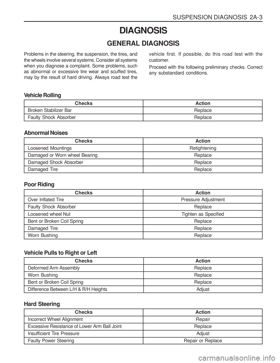
Checks
Loosened Mountings Damaged or Worn wheel BearingDamaged Shock Absorber
Damaged Tire Action
Retightening ReplaceReplaceReplace
Abnormal Noises
Checks
Broken Stabilizer Bar Faulty Shock Absorber Action
ReplaceReplace
Vehicle Rolling
Checks
Over Inflated Tire Faulty Shock Absorber Loosened wheel Nut Bent or Broken Coil Spring
Damaged TireWorn Bushing Action
Pressure Adjustment
Replace
Tighten as Specified ReplaceReplaceReplace
Poor Riding
Problems in the steering, the suspension, the tires, and the wheels involve several systems. Consider all systems when you diagnose a complaint. Some problems, suchas abnormal or excessive tire wear and scuffed tires,may by the result of hard driving. Always road test the
vehicle first. If possible, do this road test with the
customer. Proceed with the following preliminary checks. Correct any substandard conditions.
Checks
Incorrect Wheel Alignment Excessive Resistance of Lower Arm Ball Joint
Insufficient Tire PressureFaulty Power Steering
Action Repair
Replace Adjust
Repair or Replace
Hard Steering
Checks
Deformed Arm Assembly Worn BushingBent or Broken Coil SpringDifference Between L/H & R/H Heights Action
ReplaceReplaceReplace Adjust
Vehicle Pulls to Right or Left
Page 701 of 1574
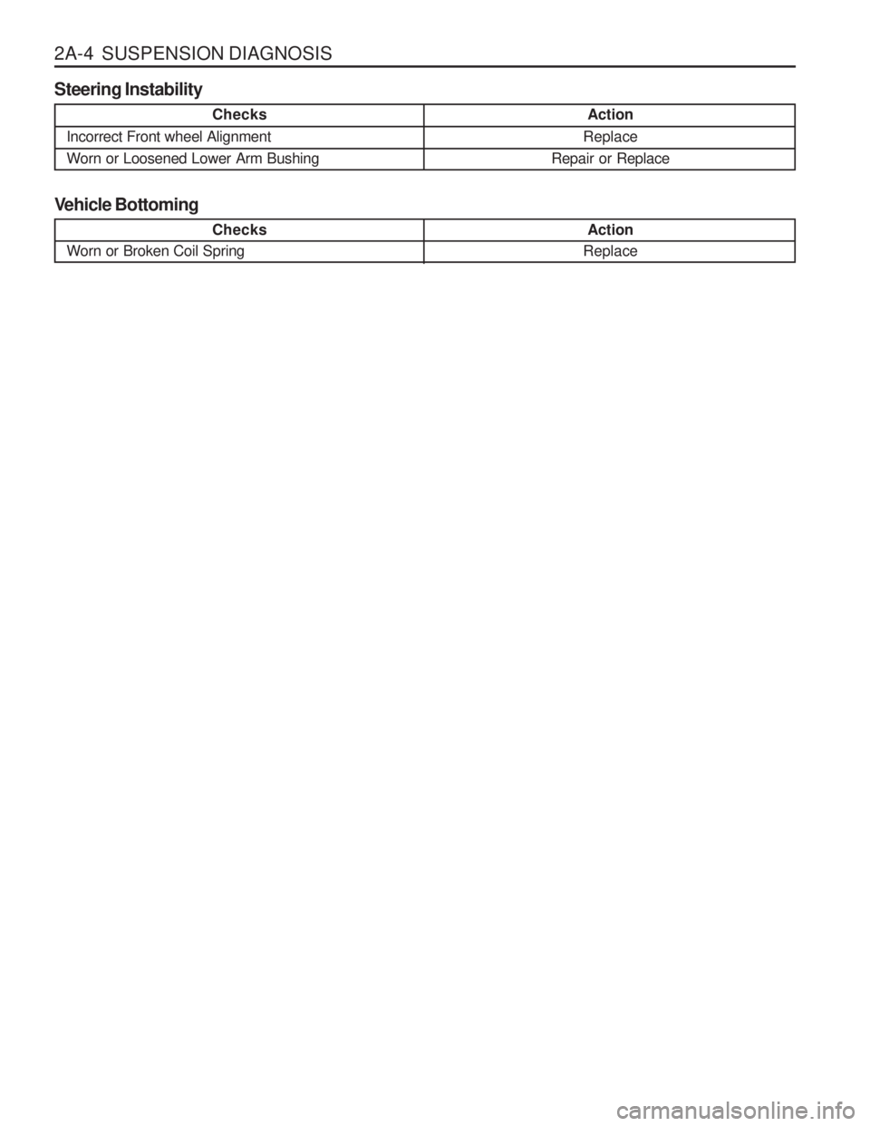
2A-4 SUSPENSION DIAGNOSISChecks
Worn or Broken Coil Spring Checks
Incorrect Front wheel Alignment Worn or Loosened Lower Arm Bushing
Action
Replace
Repair or Replace
Steering Instability
Action
Replace
Vehicle Bottoming
Page 702 of 1574
SUSPENSION DIAGNOSIS 2A-5
INPUT & OUTPUT DEVICES AND DAMPING FORCECONTROL LOGIC
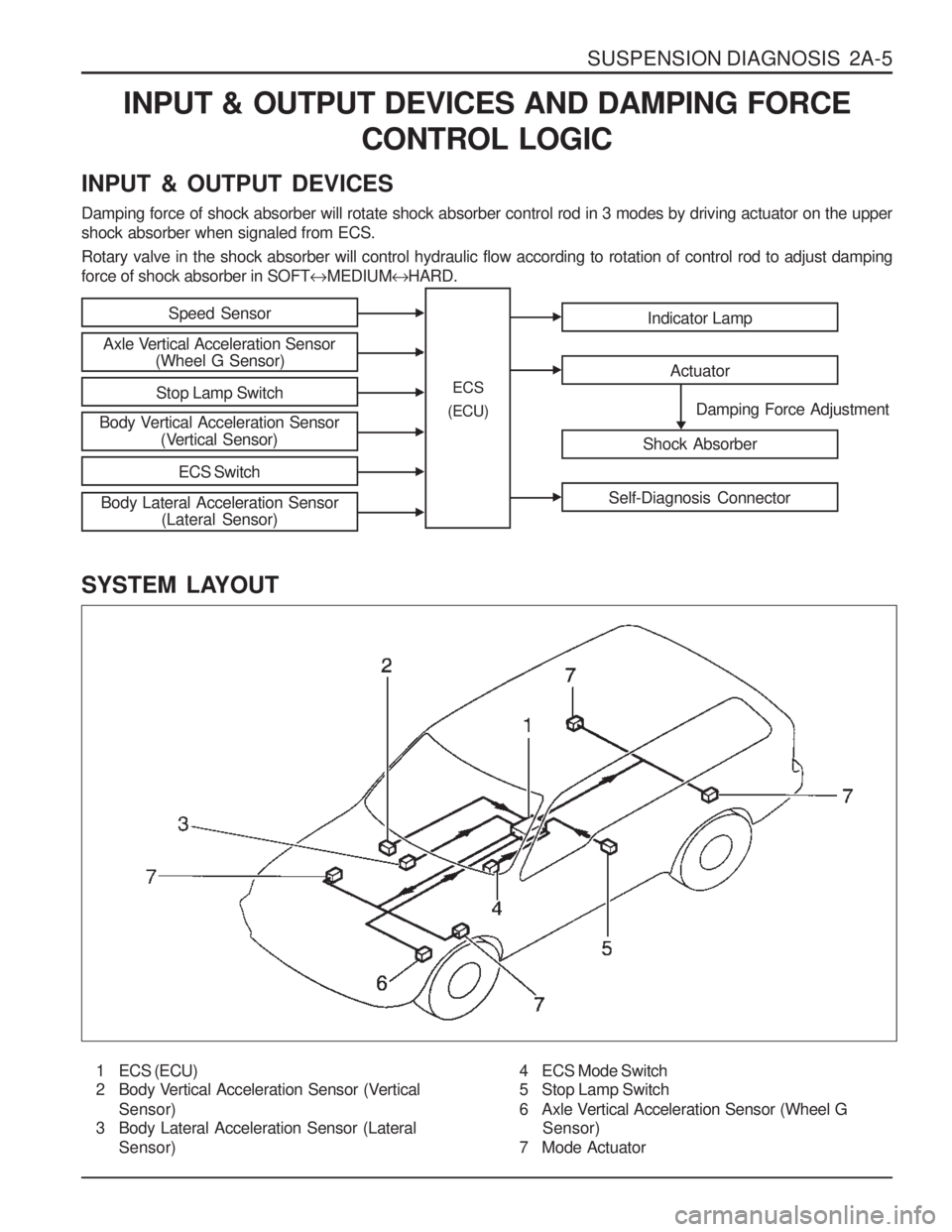
INPUT & OUTPUT DEVICES Damping force of shock absorber will rotate shock absorber control rod in 3 modes by driving actuator on the upper shock absorber when signaled from ECS. Rotary valve in the shock absorber will control hydraulic flow according to rotation of control rod to adjust damping force of shock absorber in SOFT �MEDIUM �HARD.
SYSTEM LAYOUT
1 ECS (ECU)
2 Body Vertical Acceleration Sensor (Vertical Sensor)
3 Body Lateral Acceleration Sensor (Lateral
Sensor)
Speed Sensor
Axle Vertical Acceleration Sensor (Wheel G Sensor)
Stop Lamp Switch
Body Vertical Acceleration Sensor (Vertical Sensor)
ECS Switch
Indicator Lamp
Actuator
Shock Absorber
Self-Diagnosis Connector
Damping Force Adjustment
ECS
(ECU)
Body Lateral Acceleration Sensor (Lateral Sensor)
4 ECS Mode Switch
5 Stop Lamp Switch
6 Axle Vertical Acceleration Sensor (Wheel G
Sensor)
7 Mode Actuator
Page 703 of 1574
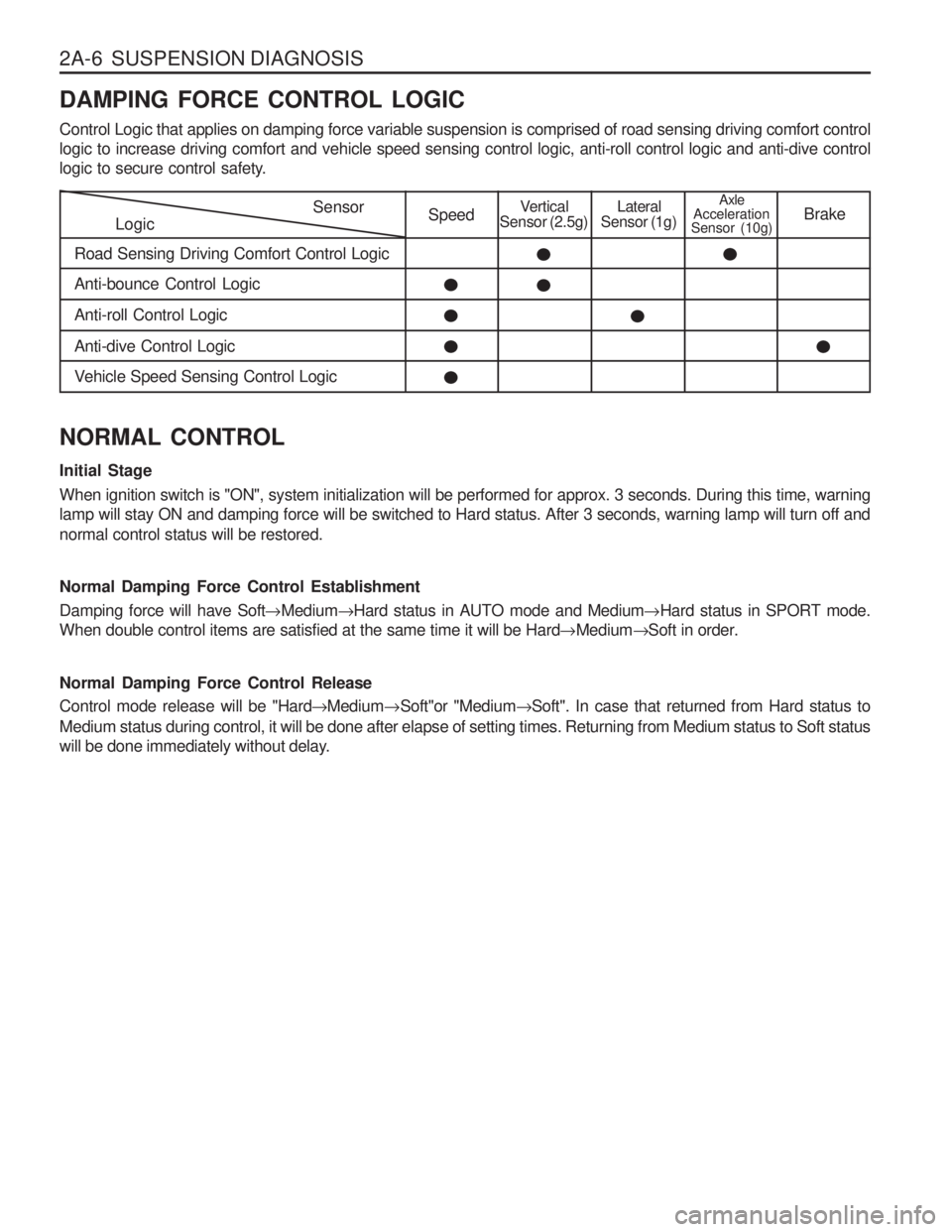
2A-6 SUSPENSION DIAGNOSIS DAMPING FORCE CONTROL LOGIC Control Logic that applies on damping force variable suspension is comprised of road sensing driving comfort control logic to increase driving comfort and vehicle speed sensing control logic, anti-roll control logic and anti-dive control
logic to secure control safety.
LogicSensor
Road Sensing Driving Comfort Control LogicSpeedVertical
Sensor (2.5g)Lateral
Sensor (1g)Axle
Acceleration
Sensor (10g) Brake
Anti-bounce Control Logic Anti-roll Control LogicAnti-dive Control Logic
Vehicle Speed Sensing Control Logic
NORMAL CONTROL Initial Stage When ignition switch is "ON", system initialization will be performed for approx. 3 seconds. During this time, warning lamp will stay ON and damping force will be switched to Hard status. After 3 seconds, warning lamp will turn off and normal control status will be restored. Normal Damping Force Control Establishment Damping force will have Soft �Medium �Hard status in AUTO mode and Medium �Hard status in SPORT mode.
When double control items are satisfied at the same time it will be Hard �Medium �Soft in order.
Normal Damping Force Control Release Control mode release will be "Hard �Medium �Soft"or "Medium �Soft". In case that returned from Hard status to
Medium status during control, it will be done after elapse of setting times. Returning from Medium status to Soft status
will be done immediately without delay.
Page 704 of 1574
SUSPENSION DIAGNOSIS 2A-7
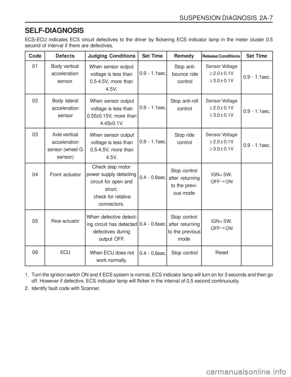
SELF-DIAGNOSIS ECS-ECU indicates ECS circuit defectives to the driver by flickering ECS indicator lamp in the meter cluster 0.5 second of interval if there are defectives.
Code
Body verticalacceleration
sensor
Defects
When sensor outputvoltage is less than
0.5-4.5V, more than
4.5V.
Judging Conditions01
0.9 - 1.1sec.Set TimeSensor Voltage
�2.0 ± 0.1V
� 3.0 ± 0.1V
Release Conditions
0.9 - 1.1sec.
Set Time
Body lateral
acceleration sensor When sensor output
voltage is less than
0.55±0.15V, more than
4.45±0.1V.
02
0.9 - 1.1sec.Sensor Voltage
�2.0 ± 0.1V
� 3.0 ± 0.1V 0.9 - 1.1sec.
Stop anti-
bounce ride
control
Remedy
Stop anti-roll control
Axle vertical
acceleration
sensor (wheel G sensor) When sensor output
voltage is less than
0.5-4.5V, more than
4.5V.
03
0.9 - 1.1sec.Sensor Voltage
�2.0 ± 0.1V
� 3.0 ± 0.1V 0.9 - 1.1sec.
Stop ride
control
Front actuator Check step motor
power supply detecting
circuit for open and
short.
check for relative connectors.
04
0.4 - 0.6sec.IGN+ SW.
OFF �
ON
Stop control
after returning to the previ-
ous mode
Rear actuator When defective detect- ing circuit has detected
defectives during
output OFF.
05
0.4 - 0.6sec.IGN+ SW.
OFF �
ON
Stop control
after returning
to the previous
mode
ECU When ECU does not
work normally.
06
0.4 - 0.6sec.Reset
Stop control
1. Turn the ignition switch ON and if ECS system is normal, ECS indicator lamp will turn on for 3 seconds and then go off. However if defective, ECS indicator lamp will flicker in the interval of 0.5 second continuously.
2. Identify fault code with Scanner.