change time SSANGYONG NEW ACTYON SPORTS 2012 User Guide
[x] Cancel search | Manufacturer: SSANGYONG, Model Year: 2012, Model line: NEW ACTYON SPORTS, Model: SSANGYONG NEW ACTYON SPORTS 2012Pages: 828, PDF Size: 91.28 MB
Page 518 of 828

06-4
1. OVERVIEW
TRIP/RESET Switch
The mode is changed each time this button is
pressed as follows: TRIP A -> TRIP B -> DTE ->
Driving time -> Average fuel economy -> Instant
fuel consumption -> Tail lamp illumination level.Windshield de-icer switch
Pressing switch activates
windshield heated glass for
approx. 12 minutes
The main switch which allows the
driver to control all door windows,
door lock and window lock from
the driver seat. Tailgate and outside
rearview mirror heated
glass switch
Pressing switch
activates tailgate and
outside rearview mirror
heated glass for
approx. 12 minutes
Driver power window switchESP ON/OFF switch
Pressing this switch deactivates the ESP
(Electronic Stability Program) system and
turns on the ESP OFF indicator on the
instrument cluster. Pressing this switch
again turns off the ESP OFF indicator and
activates the ESP system.
Outside rearview mirror folding/unfolding
switch
Press the FOLD/UNFOLD switch to fold
the outside rearview mirror and press the
switch again to unfold the mirror.
Page 521 of 828

07-4
3) Fluidic Washer Nozzle
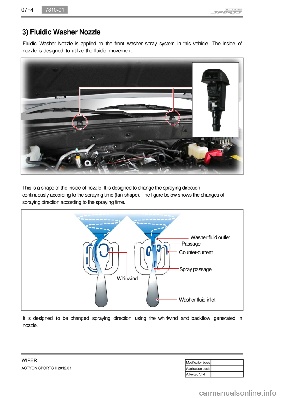
Fluidic Washer Nozzle is applied to the front washer spray system in this vehicle. The inside of
nozzle is designed to utilize the fluidic movement.
This is a shape of the inside of nozzle. It is designed to change the spraying direction
continuously according to the spraying time (fan-shape). The figure below shows the changes of
spraying direction according to the spraying time.
It is designed to be changed spraying direction using the whirlwind and backflow generated in
nozzle.Washer fluid inletSpray passage Counter-currentPassageWasher fluid outlet
Whirlwind
Page 549 of 828

01-53680-01
2. FEATURES AND SPECIFICATIONS
1) Specifications
Description DSI M78 (6-speed) Remarks
Gear ratio1st 3.53:1
2nd 2.14:1
3rd 1.48:1
4th 1.16:1
5th 0.87:1
6th 0.68:1
Reverse 3.09:1
Transmission flui
dFluid Fuchs FES 209-3292 ATF
Capacity Approx. 9.5 L
Change interval Check the fluid at every
30,000 km or 1 year, and
change it if necessary.Under the severe driving
conditions, change the fluid
at every 60,000 km.
Resistance of oil
temperature
sensor-20 430.7 ~ 533.9 kΩ
0 146.8 ~ 175.7 kΩ
20 56.74 ~ 65.86 kΩ
100 3.201 ~ 3.399 kΩ
Gear position
sensor1 -
2 -
3 -
D 2.686 kΩ ± 8%
N 5.036 kΩ ± 8%
R 8.953 kΩ ± 8%
P 16.786 kΩ ± 8%
Severe driving conditions? *
Towing a trailer or off-road driving (Inspect the
leak of fl uid at any time, occasionlly)
Taxi, patrol service or delivery service
(extended idling and excessive driving with low
speed)
Frequent stop-and-go traffi c, extended idling,
short driving distance -
-
-Driving in a hilly or mountainous terrain,
sandy, or dusty area
Driving frequently at high speed over 170
km/hour
Driving frequently in area where heavy
traffi c under the ambient temperature
above 32°C -
-
-
Page 564 of 828

01-20
3) Transmission Control Monitoring System
TCU monitors all input and output signals to identify possible failures. If a fault is detected, TCU
<0088008a009b0090009d0088009b008c009a0047009b008f008c0047009a0088008d008c009b00a0004700940096008b008c0047009b009600470092008c008c00970047009b008f008c0047008b00990090009d008c009902c5009a0047009a0088008d00
8c009b00a0004700880095008b0047009b008f008c00470093>ife span of transmission.
Monitoring the Supply Voltage ▶
Monitoring the Supply Voltage to Solenoid ▶
Monitoring the Gear Ratio ▶
Monitoring the Torque Converter ▶ If the battery voltage is too high or too low, the TCU sets the DTC.
TCU monitors the circuits for open or short to ground or supply. The monitoring function
evaluates the voltage characteristics while the switch is ON.
TCU monitors the gear is engaged properly in the allowed time.
TCU checks if the torque converter can be locked up properly. If it is failed, TCU releases the
torque converter clutch to activate the fail-safe operation.
4) Shift Energy Management
This function involves reducing or increasing the engine output torque during shifting. This
reduces the energy which is dissipated in the friction elements of the transmission during up-
shift. This is done by reducing the engine torque during the gear ratio change without interrupting
the tractive drive.
This function is used for:
Increasing the life span of transmission by shortening the slipping time
Improving the shift comfort by reducing the step changes due to gearshift
Transferring a higher engine power -
-
-
Real-time control of engine torque is required to maintain the proper shift operations and the
durability of transmission. TCU controls the engine torque during the gearshift by synchronizing
the operation of transmission clutches.
Page 593 of 828

02-33170-01
Description Specification
Gear ratio 1st 4.489 : 1
2nd 2.337 : 1
3rd 1.350 : 1
4th 1.000 : 1
5th 0.784 : 1
6th 0.679 : 1
Reverse 4.253 : 1
Synchronizer
ring type1st T: Triple-cone
2nd T: Triple-cone
3rd T: Triple-cone
4th S: Single-cone
5th D: Double-cone
6th S: Single-cone
Reverse T: Triple-cone
Shifting Type Floor change type
Gear selector
lever position
Transmission
fluidType HD MTF 75W/85 (SHELL) or HK MTF 75W/85(SK)
Capacity
Sercive interval Inspect and replenish every 60000 km or 3 years (under
severe driving conditions, change every 120,000 km)
1. SPECIFICATION
Reversing:
High-force type
What’s the severe conditions?
Towing a trailer or off-road driving (Inspect
the leak of fluid at any time, occasionlly)
Taxi, patrol service or delivery service
(extended idling and excessive driving with
low speed)
Frequent stop-and-go traffic, extended
idling, short driving distance -
-
-Driving in a hilly or mountainous terrain,
sandy, or dusty area
Driving frequently at high speed over 170
km/hour
Driving frequently in area where heavy
traffic under the ambient temperature
above 30°C -
-
-
Page 619 of 828

04-4
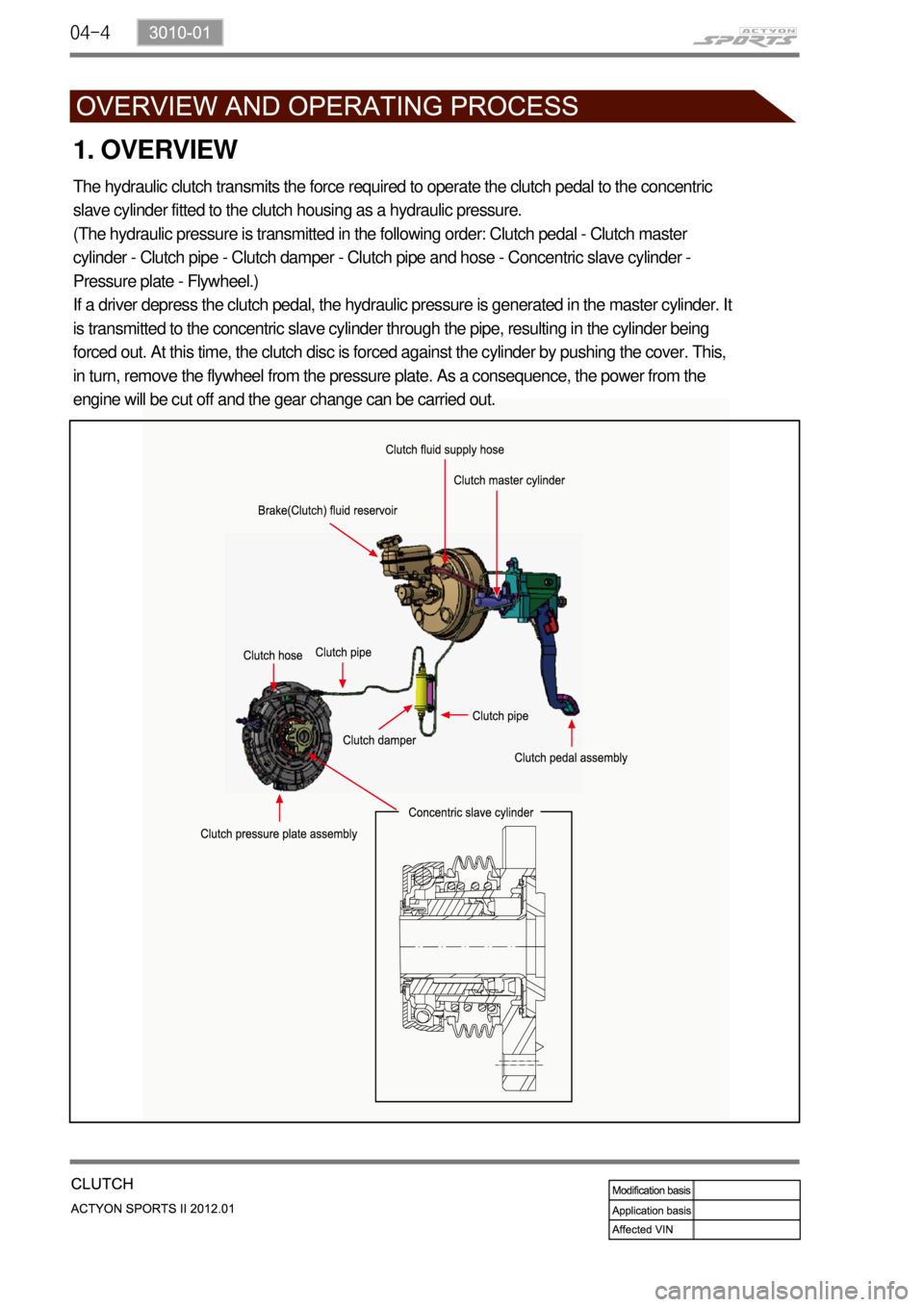
1. OVERVIEW
The hydraulic clutch transmits the force required to operate the clutch pedal to the concentric
slave cylinder fitted to the clutch housing as a hydraulic pressure.
(The hydraulic pressure is transmitted in the following order: Clutch pedal - Clutch master
cylinder - Clutch pipe - Clutch damper - Clutch pipe and hose - Concentric slave cylinder -
Pressure plate - Flywheel.)
If a driver depress the clutch pedal, the hydraulic pressure is generated in the master cylinder. It
is transmitted to the concentric slave cylinder through the pipe, resulting in the cylinder being
forced out. At this time, the clutch disc is forced against the cylinder by pushing the cover. This,
in turn, remove the flywheel from the pressure plate. As a consequence, the power from the
engine will be cut off and the gear change can be carried out.
Page 664 of 828

09-16
Let the engine run for 1 to 2 minutes and
stop it. If the brake pedal stroke is
shortened as pumping the brake pedal,
the system is normal. If not, the system is
defective.
Depress the brake pedal several times
with engine off. If the brake goes down
when starting engine with pedal
depressed, the system is normal. If not,
the system is defective.
Depress the brake pedal when the engine
is running. If the pedal height is not
changed for 30 seconds after stopping
the engine, the system is normal. If not,
the system is defective. 1.
2.
3.
If the above three checks are OK, the system
is normal. If any condition is not met, check
the valve, vacuum hose and brake booster. Brake Booster ▶
Page 710 of 828

11-94890-10
3. PRECAUTIONS
The warning lamp flashes and warning beep sounds when the ESP is operating
When the ESP operates during vehicle movement, the ESP warning lamp on the instrument
panel flashes and beep comes on every 0.1 second. The ESP system is only a
supplementary device for comfortable driving. When the vehicle exceeds its physical limits, it
cannot be controlled.
Do not rely on the system. Keep on the safe driving.
Feeling when ESP is working
When the ESP system activates, the feeling can be different depending on vehicle driving
conditions.
For example, you will feel differently when the ESP system is activated during the ABS is
operating with the brakes applied and when the brakes are not applied on a curve.
If the ESP system operates when the brake is applied, the brake pressure will be increased on
the corresponding wheel which already has braking pressure for the ESP controls.
ARP Operation
During the ARP operation, vehicle safety (rollover prevention) takes the first priority and thus,
stronger engine control is in effect. Consequently, the vehicle speed decreases rapidly, so the
driver must take caution for the vehicle may drift away from the lane.
Noise and vibration that driver feels when ESP system is operating
The ESP system may transfer noise and vibration to the driver due to the pressure changes
caused by the motor and valve operations in a very short period of time. And, keep in mind
that the output and vehicle speed could be decreased without rpm increase due to the ASR
function that controls the engine power.
Page 720 of 828

11-194890-10
Circuit description ▶
When compared to the vehicle equipped with ABS/EBD only, the internal hydraulic circuit has a
normally-open separation valve and a shuttle valve in primary circuit and in secondary circuit.
When the vehicle brakes are not applied during engine running or when applying the non-ABS
operating brakes, the normally-open separation valve and the inlet valve are open, whereas the
normally-closed shuttle valve and the outlet valve are closed.
When the ESP system is operating, the normally-open separation valve will be closed by the
solenoid valve operation and the hydraulic circuit will be established by the shuttle valve. Then,
the inlet and outlet valves will be closed or open depending on the braking pressure RISE, HOLD
or DUMP conditions.
Flashing warning lamp and warning sound during ESP operation ▶
When the ESP operates while the vehicle is moving, the ESP warning lamp on the instrument
panel flickers and the buzzer sounds at every 0.1 second. The ESP lamp operation is to inform a
driver that the vehicle is extremely unstable.
The ESP system is just a supplementary system for the vehicle and it cannot control the vehicle
over the physical limit. Do not solely rely on the system but be advised to drive the vehicle safely.
Drive feeling during ESP operation ▶
When the ESP system activates, the driving feeling can be different depending on vehicle driving
conditions. For example, it will feel different when the ESP system is activated while the ABS is
operated by depressing the brake pedal and when the ESP system is in control without the brake
pedal depressed on the same curve.
If the ESP system operates with the brake applied, the brake pressure will be increased on the
corresponding wheel which already has braking pressure for the ESP controls. In other words, the
ESP system would make the driver feel more abruptly braked compared to the situation that the
braking pressure is applied to wheel which had no braking force.
Noise and vibration that driver senses during ESP operation ▶
The ESP system may transfer noise and vibration to a driver due to the pressure changes caused
by the motor and valve operations in a very short period of time.
Extreme cornering will trigger the ESP operation and this will make the driver sense noise and
vibration due to sudden brake application.
Also, the ESP system controls the engine power. Therefore, the driver may notice the engine
power decreases even when the accelerator pedal is depressed.
Page 737 of 828

12-114610-01
Oil Change ▶
Open the power fluid reservoir cap and
drain the fluid completely with oil suction
device. To make it easy, turn the steering
wheel to its both ends several times.
Fill up the specified fluid into fluid reservoir
and bleed air from the steering system. 1.
2. Oil Level Check ▶
Place the vehicle on a level ground and
start the engine and let it run at idle speed.
Turn the steering wheel several times so
that the oil temperature reaches to normal
operating level (75~85˚C).
Place the steering wheel at straight ahead
direction.
Check the oil level in the power steering oil
reservoir. Adjust the oil level between MAX
and MIN. 1.
2.
3.
4.
If the difference between two
measurements is below 5 mm and the level
is between MAX and MIN level, it's normal.
If it is over 5 mm, bleed air from the
system. Check the fluid level on a level ground with
the engine turned off. The fluid level should
be between the MIN and MAX marks on the
reservoir cap gauge.
below 5 mm
Engine idling Engine running
Oil typeATF Dexron II or III
Capacityapprox. 1ℓ (including
reservoir)