SSANGYONG NEW ACTYON SPORTS 2012 Service Manual
NEW ACTYON SPORTS 2012
SSANGYONG
SSANGYONG
https://www.carmanualsonline.info/img/67/57513/w960_57513-0.png
SSANGYONG NEW ACTYON SPORTS 2012 Service Manual
Trending: sunroof, jacking, glove box, door lock, parking brake, steering, coolant capacity
Page 261 of 828
09-111451-01
2. OPERATING PROCESS
1) Charging Flow
Page 262 of 828

09-12
Alternator (140 A)Alternator (120 A)
2) Charging
The alternator uses a new regulator which has three diodes. It consists of the delta stator, rectifier
bridge, slip ring and brush.
Charging time according to vehicle conditions and environment ▶
Specification: Charging a fully depleted high-
capacity battery takes twice or more as long
as charging a fully depleted battery for small
vehicles.
Temperature: The lower the temperature is,
the longer the time taken to charge the
battery. When connecting the battery charger
to the cold battery, the amount of current the
battery can accept initially is very small. As the
battery gets warmer, it can accept more
current.
Charging capacity: Charging a battery with a low-capacity charger takes longer time than
charging with a high-capacity charger.
Charging status: Charging a fully depleted battery takes twice or more as long as charging a half-
depleted battery. Since the electrolyte in a fully depleted battery consists of nearly pure water and
conductor, only a very small amount of current can be accepted by the battery initially. The
charging current increases as the amount of acids in the electrolyte is increased by the charging
current.
3) Output Characteristics
Page 263 of 828
09-131451-01
3. CIRCUIT DIAGRAM
Page 264 of 828
10-31413-00
1. SPECIFICATION
Description Specification
Glow plug Rated voltage 12 V
Operating voltage 6 ~ 16 V
Maximum temperature1300°C
Operating temperature1100°C
Glow plug control unit EMS operating voltage 6 ~ 16 V
Operating temperature-40°C ~ 110°C
Dark current Max. 1 mA
Page 265 of 828
10-4
Glow plug control unit
(GCU)
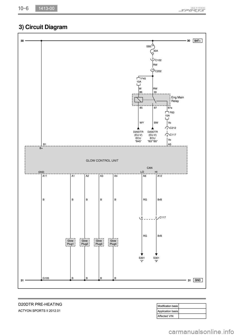
1. OVERVIEW
The pre-heating system for D20DTR engine has the glow plug to the cylinder head (combustion
chamber), and improves the cold start performance and reduces the emission level.
The pre-heating resistor (air heater) is used to heat the intake air.
This enables the diesel fuel to be ignited in low temperature condition.
The ECU receives the information such as, engine rpm, coolant temperature, engine torque, etc.,
through CAN communication during pre-heating process; and the pre-heating control unit
controls the pre-heating, heating during cranking and post-heating by the PWM control.
Glow plug
Glow indicatorEngine ECU (D20DTR)
Page 266 of 828
10-51413-00
2. SYSTEM OPERATION
1) Input/Output Diagram of Glow Plug Control Unit
2) System Diagram
Page 267 of 828
Page 268 of 828

10-71413-00
4) Operation
Glow plug is installed in the cylinder head. It enhances the cold starting performance and reduces
the exhaust gas during cold starting.
(1) Operation
Duty control area:
Between 5 and 100%
Frequency: 20 Hz
Duty ratio = (RMS voltage)²
(Battery voltage)² 1.
2.
3.
Pre-Glow: Step 1 ▶
If normal communication with the ECU is established 2 seconds after the power is supplied to the
IGN terminal from the battery, the GCU supplies the battery power to raise the temperature of the
<008e00930096009e004700970093009c008e0047009b0096004700580057005700570b450047008900a00047009b008f008c004700970099008c0054008f008c0088009b00900095008e00470099008c0098009c008c009a009b0047008d00990096009400
47009b008f008c0047008c0095008e00900095008c0047006c>CU before starting.
Pre-
heatingCoolant
temperature-30°C -25°C -20°C -10°C -5°C 0°C 20°C
Operating time
28 s 25 s 15 s 5 s 2 s 2 s 0 s
Operating
conditions- IGN: ON
- B+: below 15.2 VStop
conditions- Time-out
- IGN: OFF
- when engine cranking
If the input power (VB) is 11.5 V or less, the GCU supplies the battery power for arrival time
(T1).
If the input power (VB) is greater than 11.5 V, the GCU supplies the voltage of 11.5 V for arrival
time (T1). 1.
2.
- The time for pre-heating is controlled by the ECU.
The time for pre-heating by coolant temperature can vary slightly depending on e.g. other
vehicle operation elements.
Page 269 of 828

10-8
During cranking: Step 2 and step 3 ▶
Step 2: If the ECU receives the cranking signal after pre-heating (step 1), the GCU supplies the
<009d00960093009b0088008e008c00470096008d0047005d0055005f0047007d0047008d00960099004700580047009a008c008a0047009b00960047009900880090009a008c0047009b008f008c0047009b008c00940097008c00990088009b009c009900
8c0047009b00960047005800530058005700570b450055>
Step 3: The GCU supplies the voltage of 5.1 V to keep the temperature at 1,000°C. 1.
2.
Under fixed temperature: The AQGS unit supplies power for 30 seconds (Step 1 + Step 3)
if no cranking signal is received after the step 1.
At cranking: The step 3 is started after the step 2. *
*
Post-glow: Step 4: ▶
The post-heating is for reducing HC/CO after the engine is started. If the time for post-heating
exceeds 180 sec., the GCU unit cuts off the power to each glow plug even if there is pre-heating
request from the engine ECU.
Post-
heatingOperating time
(approx.)-20°C -10°C 0°C 20°C 80°C
Operating time
(approx.)100 s 50 s 25 s 10 s 10 s
Emergency glow ▶
If no CAN signal is received for 4 seconds from the engine ECU after the IGN ON signal is input,
the GCU performs emergency preheat (Step 3) for 30 seconds.
P1 to P2: Pre glow
P3 to P4: Post glow
Page 270 of 828
11-31461-01
1. SPECIFICATION
Description Specification
Capacity 12 V, 2.3 kW
Engagement Meshed type
Rotating direction Clockwise
Pinion gear manufacturing Cooled forging
Solenoid operating voltage Max. 8 V
Weight 2.5 kg
Bracket manufacturing Aluminum die casting
Trending: ESP, relay, steering, radiator cap, oil capacity, wheel bolts, air filter


