check engine SSANGYONG NEW ACTYON SPORTS 2012 Workshop Manual
[x] Cancel search | Manufacturer: SSANGYONG, Model Year: 2012, Model line: NEW ACTYON SPORTS, Model: SSANGYONG NEW ACTYON SPORTS 2012Pages: 828, PDF Size: 91.28 MB
Page 497 of 828

04-6
Connector Pin Arrangement ▶
The connector pin sections illustrated below are viewed from the front of the instrument
cluster. The arrangement of the pins is the same for both the main connector and the sub
connector.
Main connector - 20-pin (white)
Sub connector - 20-pin (gray)
1. -
2. Hood open
3. Seat belt - passenger's seat
4. -
5. -
6. Front fog lamp
7. -
8. Engine CHECK warning light
9. Charge
10. IGN 2
11. -
12. Air bag
13. Seat belt - driver's seat
14. High beam (-)
15. Right turn signal lamp (+)
16. High beam (+)
17. Left turn signal lamp (+)
18. Oil pressure
19. Parking brake signal input (STICS)
20. - 1. -
2. -
3. 4P output
4. Buzzer output
5. Illumination (+)
6. -
7. -
8. Door open
9. -
10. Battery
11. -
12. Fuel input signal
13. TRIP mode/reset switch
14. Manual transmission N (neutral)
input
15. Manual transmission R (reverse)
input
16. CAN LOW
17. CAN HIGH
18. AGND (fuel -)
19. MICOM ground
20. IGN 1
Page 499 of 828

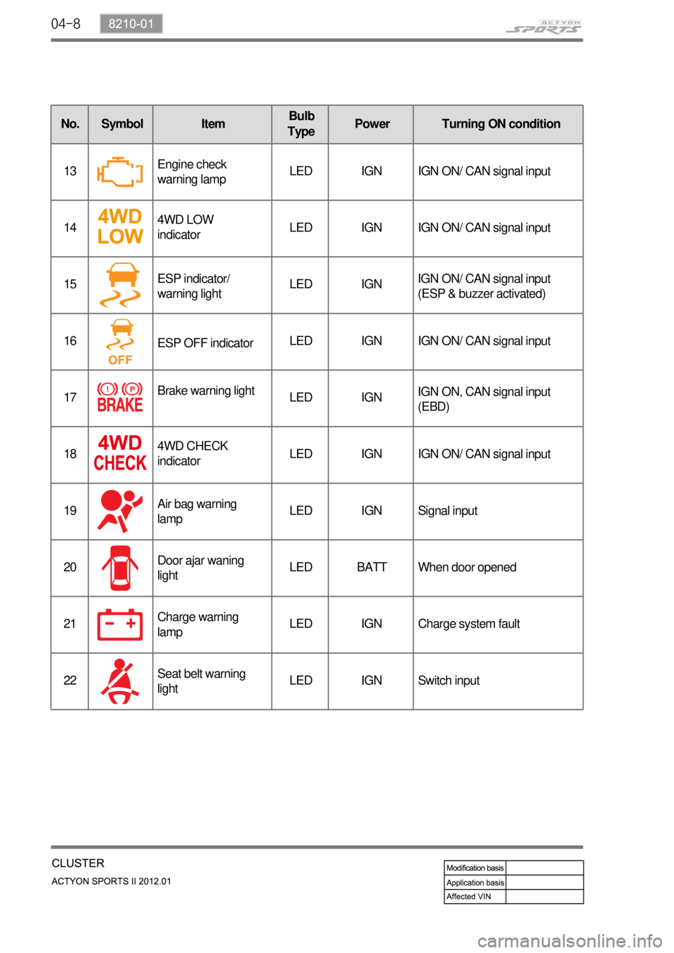
04-8
No. Symbol ItemBulb
TypePower Turning ON condition
13Engine check
warning lampLED IGN IGN ON/ CAN signal input
144WD LOW
indicatorLED IGN IGN ON/ CAN signal input
15ESP indicator/
warning lightLED IGNIGN ON/ CAN signal input
(ESP & buzzer activated)
16
ESP OFF indicatorLED IGN IGN ON/ CAN signal input
17Brake warning light
LED IGNIGN ON, CAN signal input
(EBD)
184WD CHECK
indicatorLED IGN IGN ON/ CAN signal input
19Air bag warning
lampLED IGN Signal input
20Door ajar waning
lightLED BATT When door opened
21Charge warning
lampLED IGN Charge system fault
22Seat belt warning
lightLED IGN Switch input
Page 501 of 828

04-10
2. CONFIGURATION
1) RPM Gauge
The tachometer indicates engine speed in revolutions per minute. Multiply 1,000 to the current
number, then it will be the current number of engine revolutions.
Under the normal engine operating temperature, the proper idling speed is 700 ~ 800 rpm. The
red zone (danger rpm range) starts from 4,500 rpm.
Connect the tachometer for tune-up test and start the engine.
Eliminate the hysteresis by tapping the tachometer.
Compare the values on the tester and tachometer and replace the tachometer if the tolerance
is excessive. 1.
2.
3.
If the tachometer (engine rpm gauge) pointer vibrates or stops moving at a certain range, or
abnormal noises are heard from the tachometer, the tachometer may have a malfunction. If
you have reason to suspect that the reading from the tachometer differs from the actual engine
speed (rpm), connect a diagnostic device and compare the value on tachometer with the
reading from the diagnostic device.
Check Method
Page 511 of 828

04-20
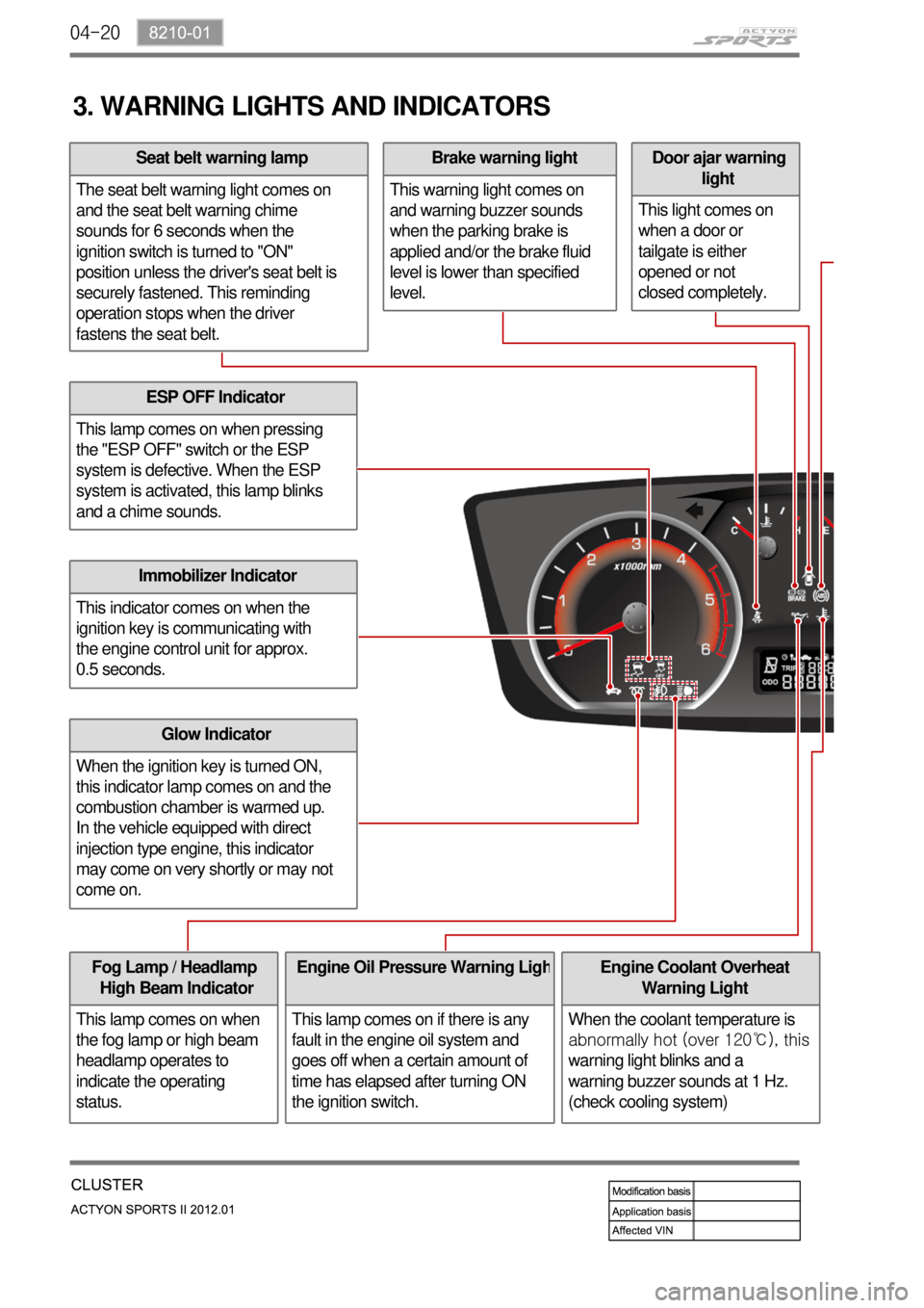
3. WARNING LIGHTS AND INDICATORS
ESP OFF Indicator
This lamp comes on when pressing
the "ESP OFF" switch or the ESP
system is defective. When the ESP
system is activated, this lamp blinks
and a chime sounds.
Immobilizer Indicator
This indicator comes on when the
ignition key is communicating with
the engine control unit for approx.
0.5 seconds.
Glow Indicator
When the ignition key is turned ON,
this indicator lamp comes on and the
combustion chamber is warmed up.
In the vehicle equipped with direct
injection type engine, this indicator
may come on very shortly or may not
come on.
Fog Lamp / Headlamp
High Beam Indicator
This lamp comes on when
the fog lamp or high beam
headlamp operates to
indicate the operating
status.Engine Oil Pressure Warning Ligh
This lamp comes on if there is any
fault in the engine oil system and
goes off when a certain amount of
time has elapsed after turning ON
the ignition switch.
Door ajar warning
light
This light comes on
when a door or
tailgate is either
opened or not
closed completely.Brake warning light
This warning light comes on
and warning buzzer sounds
when the parking brake is
applied and/or the brake fluid
level is lower than specified
level.Seat belt warning lamp
The seat belt warning light comes on
and the seat belt warning chime
sounds for 6 seconds when the
ignition switch is turned to "ON"
position unless the driver's seat belt is
securely fastened. This reminding
operation stops when the driver
fastens the seat belt.
Engine Coolant Overheat
Warning Light
When the coolant temperature is
abnormally hot (over 120℃), this
warning light blinks and a
warning buzzer sounds at 1 Hz.
(check cooling system)
Page 512 of 828

04-218210-01
ABS Warning Light
This warning light comes on
when the ignition switch is
turned to "ON" position and
should go out if the system is
normal.
The vehicle with ABS performs
self-diagnosis. During this
diagnosis, brake pedal
vibration and noise may be
apparent when the driving
motors discharges the
hydraulic pressure from the
internal hydraulic device.4WD IndicatorLow Fuel Level
Warnig Light
This warning light
comes on when the
fuel will soon be
exhausted. The time
it takes turn on,
however, varies
according to the
gradient of the
vehicle.
4WD HIGH Indicator
The lamp blinks momentarily during
the change of driving mode.
4WD LOW Indicator
The lamp blinks momentarily during
the change of driving mode.
4WD CHECK Warning Light
This indicates that there is
something wrong in the transfer
case system. (check the system) -
-
-
Auto Cruise Control
Indicator
Operating the cruise
control switch turns on
the indicator lamp to
indicate the cruise
control system is
activated.
Water Separator Warning Light
This lamp comes on to warn the driver of
water in the fuel tank which causes the
loss of engine power. When a certain
amount of water is accumulated, the lamp
comes on and a chime sounds.
Engine CHECK Warning Light
This warning light comes on when
the ignition switch is turned to "ON"
position and should go out if the
system related to engine control is
normal.
This comes on when different
sensors and devices related to
engine control are defective.
Winter Mode
Indicator
Pressing the "W" side of the
automatic transmission mode
selector switch switches the
driving mode to winter mode and
turns on the indicator lamp.
Use this mode to drive off
smoothly on icy and slippery
roads.
Charge Warning Light
This warning light comes on when the
ignition switch is turned on and go off
when the engine is started.
If this light doesn't go off after engine
starting, it means there is a malfunction in
the system.
Engine Hood Open Warning Light
When the engine hood is open, this light
comes on to inform the driver.
Page 513 of 828

04-22
How to enter self-diagnosis mode ▶
Turn the ignition ON with the TRIP switch pressed.
Press and hold the TRIP switch for 5 to 10 sec. with the ignition ON.
Press and hold the TRIP switch for less than 10 sec. and then cycle the switch between ON
and OFF 5 times within 3 sec.
Confirm that the self-diagnosis mode is activated through the instrument cluster. 1.
2.
3.
4.
4. SELF-DIAGNOSIS CHECK
Self-diagnosis OFF ▶
If the engine speed increases to 396 rpm or more while the engine is cranking or the ignition key
is turned OFF in self-diagnosis mode, the self-diagnosis mode is turned OFF automatically.
Operating process ▶
Speed gauge: changes from 0 to 220 km
RPM gauge: changes from 0 to 6,000 rpm
Fuel gauge: changes from E to F
Temperature gauge: changes from C to H
Warning/Indicator lamps: All indicator/warning lamps controlled by MICOM are turned ON.
Dimming: Illuminates at the highest lighting level.
LCD display: All elements are activated. 1.
2.
3.
4.
5.
6.
7.
Page 564 of 828

01-20
3) Transmission Control Monitoring System
TCU monitors all input and output signals to identify possible failures. If a fault is detected, TCU
<0088008a009b0090009d0088009b008c009a0047009b008f008c0047009a0088008d008c009b00a0004700940096008b008c0047009b009600470092008c008c00970047009b008f008c0047008b00990090009d008c009902c5009a0047009a0088008d00
8c009b00a0004700880095008b0047009b008f008c00470093>ife span of transmission.
Monitoring the Supply Voltage ▶
Monitoring the Supply Voltage to Solenoid ▶
Monitoring the Gear Ratio ▶
Monitoring the Torque Converter ▶ If the battery voltage is too high or too low, the TCU sets the DTC.
TCU monitors the circuits for open or short to ground or supply. The monitoring function
evaluates the voltage characteristics while the switch is ON.
TCU monitors the gear is engaged properly in the allowed time.
TCU checks if the torque converter can be locked up properly. If it is failed, TCU releases the
torque converter clutch to activate the fail-safe operation.
4) Shift Energy Management
This function involves reducing or increasing the engine output torque during shifting. This
reduces the energy which is dissipated in the friction elements of the transmission during up-
shift. This is done by reducing the engine torque during the gear ratio change without interrupting
the tractive drive.
This function is used for:
Increasing the life span of transmission by shortening the slipping time
Improving the shift comfort by reducing the step changes due to gearshift
Transferring a higher engine power -
-
-
Real-time control of engine torque is required to maintain the proper shift operations and the
durability of transmission. TCU controls the engine torque during the gearshift by synchronizing
the operation of transmission clutches.
Page 661 of 828

09-134850-01
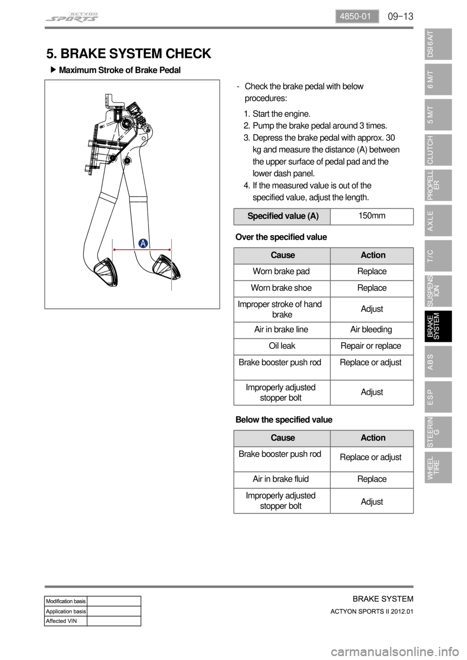
Maximum Stroke of Brake Pedal ▶
Check the brake pedal with below
procedures: -
Start the engine.
Pump the brake pedal around 3 times.
Depress the brake pedal with approx. 30
kg and measure the distance (A) between
the upper surface of pedal pad and the
lower dash panel.
If the measured value is out of the
specified value, adjust the length. 1.
2.
3.
4.
Specified value (A)150mm
5. BRAKE SYSTEM CHECK
Over the specified value
Cause Action
Worn brake pad Replace
Worn brake shoe Replace
Improper stroke of hand
brakeAdjust
Air in brake line Air bleeding
Oil leak Repair or replace
Brake booster push rod Replace or adjust
Improperly adjusted
stopper boltAdjust
Below the specified value
Cause Action
Brake booster push rod
Replace or adjust
Air in brake fluid Replace
Improperly adjusted
stopper boltAdjust
Page 662 of 828

09-14
Specified value (B)155mm
Push rod
Stop lamp
switch Pedal Height ▶
Check the pedal height with below
procedures: -
Start the engine and measure the length
(A) between floor mat and pedal.
If the measured value is out of the
specified value, adjust the length. 1.
2.
Adjust the pedal height with below
procedures: -
Disconnect the stop lamp switch connector.
Unscrew the lock nut and remove the stop
lamp switch assembly.
Loosen the lock nut on the pedal push rod.
Turn the pedal push rod to adjust the pedal
height.
Tighten the lock nut.
Install the stop lamp switch assembly.
Connect the stop lamp switch connector.
Check if the stop lamps come on when
pressing the brake pedal around 5 mm.
If the stop lamp dpes not come on, adjust
the stop lamp switch assembly again.
If the stop lamps come on, tighten the lock
nut and measure the pedal height again. 1.
2.
3.
4.
5.
6.
7.
8.
9.
10.
Page 663 of 828

09-154850-01
Specified value (A)3 ~ 10mm
Connect the multimeter to stop lamp
switch connector and check if the
continuity exists when pushing in the
plunger. If the continuity doesn't exist, the
stop lamp switch is normal. - Pedal Free Play ▶
Stop Lamp Switch ▶Check the pedal free play with below
procedures: -
Stop the engine.
Depress the brake pedal several times to
discharge the vacuum pressure of the brake
booster.
Depress the brake pedal until you feel the
resistance, and measure the movement (A). 1.
2.
3.
Below the specified value: Check if the
distance between the outer case of stop
lamp switch and the brake pedal.
Over the specified value: It may be caused
by bigger clearance between the clevis pin
and the brake pedal arm. Replace the
components if necessary. -
-