lamp SSANGYONG NEW ACTYON SPORTS 2013 User Guide
[x] Cancel search | Manufacturer: SSANGYONG, Model Year: 2013, Model line: NEW ACTYON SPORTS, Model: SSANGYONG NEW ACTYON SPORTS 2013Pages: 751, PDF Size: 72.63 MB
Page 142 of 751
08-4
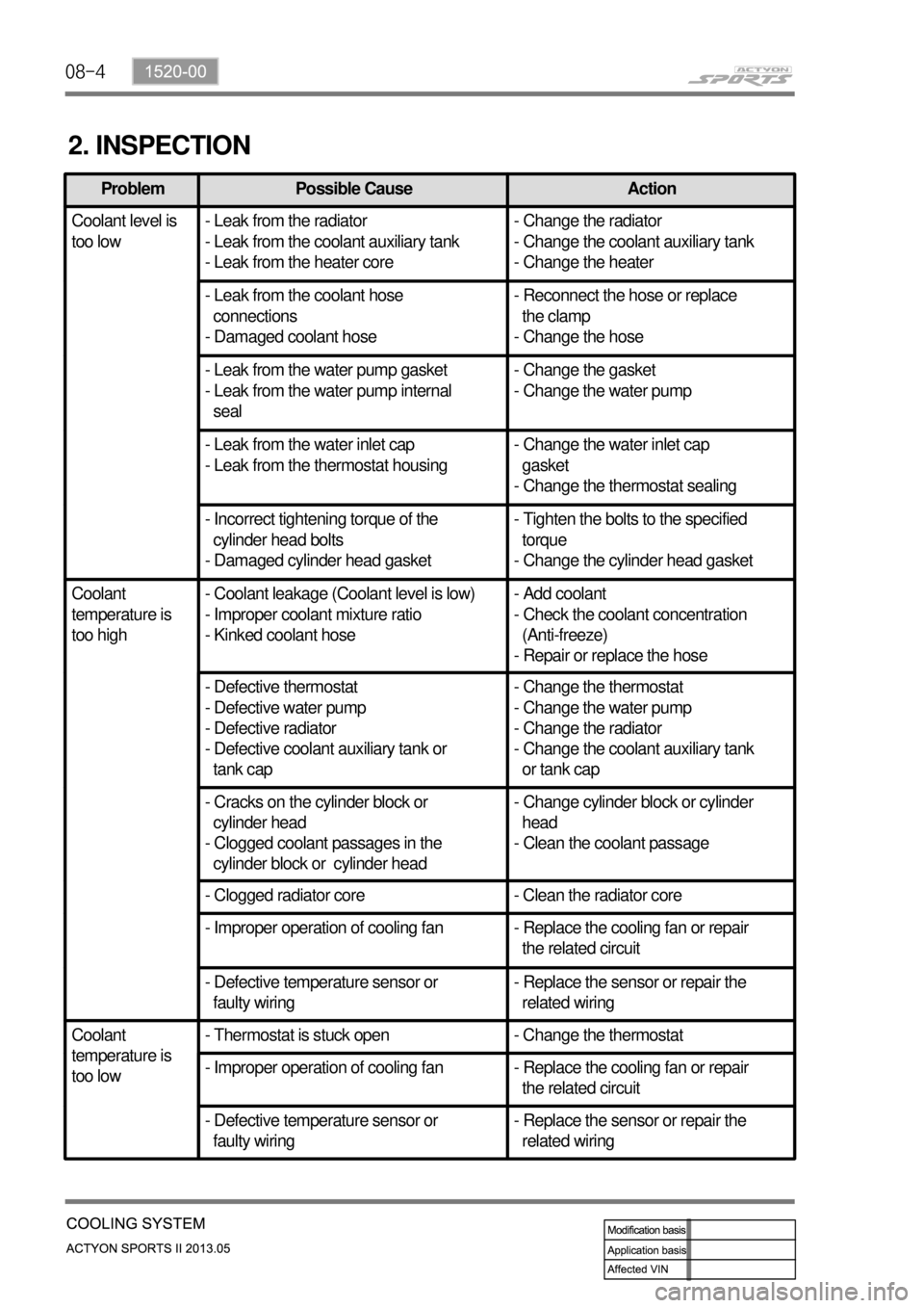
2. INSPECTION
Problem Possible Cause Action
Coolant level is
too low- Leak from the radiator
- Leak from the coolant auxiliary tank
- Leak from the heater core- Change the radiator
- Change the coolant auxiliary tank
- Change the heater
- Leak from the coolant hose
connections
- Damaged coolant hose- Reconnect the hose or replace
the clamp
- Change the hose
- Leak from the water pump gasket
- Leak from the water pump internal
seal- Change the gasket
- Change the water pump
- Leak from the water inlet cap
- Leak from the thermostat housing- Change the water inlet cap
gasket
- Change the thermostat sealing
- Incorrect tightening torque of the
cylinder head bolts
- Damaged cylinder head gasket- Tighten the bolts to the specified
torque
- Change the cylinder head gasket
Coolant
temperature is
too high- Coolant leakage (Coolant level is low)
- Improper coolant mixture ratio
- Kinked coolant hose- Add coolant
- Check the coolant concentration
(Anti-freeze)
- Repair or replace the hose
- Defective thermostat
- Defective water pump
- Defective radiator
- Defective coolant auxiliary tank or
tank cap- Change the thermostat
- Change the water pump
- Change the radiator
- Change the coolant auxiliary tank
or tank cap
- Cracks on the cylinder block or
cylinder head
- Clogged coolant passages in the
cylinder block or cylinder head- Change cylinder block or cylinder
head
- Clean the coolant passage
- Clogged radiator core - Clean the radiator core
- Improper operation of cooling fan - Replace the cooling fan or repair
the related circuit
- Defective temperature sensor or
faulty wiring- Replace the sensor or repair the
related wiring
Coolant
temperature is
too low- Thermostat is stuck open - Change the thermostat
- Improper operation of cooling fan - Replace the cooling fan or repair
the related circuit
- Defective temperature sensor or
faulty wiring- Replace the sensor or repair the
related wiring
Page 149 of 751
09-4
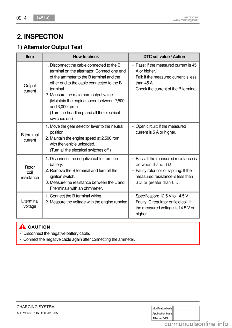
2. INSPECTION
1) Alternator Output Test
Item How to check DTC set value / Action
Output
current
B terminal
current
Rotor
coil
resistance
L terminal
voltage
Disconnect the cable connected to the B
terminal on the alternator. Connect one end
of the ammeter to the B terminal and the
other end to the cable connected to the B
terminal.
Measure the maximum output value.
(Maintain the engine speed between 2,500
and 3,000 rpm.)
(Turn the headlamp and all the electrical
switches on.) 1.
2.Pass: If the measured current is 45
A or higher.
Fail: If the measured current is less
than 45 A.
Check the current of the B terminal. -
-
-
Move the gear selector lever to the neutral
position.
Maintain the engine speed at 2,500 rpm
with the vehicle unloaded.
(Turn all the electrical switches off.) 1.
2.Open circuit: If the measured
current is 5 A or higher. -
Disconnect the negative cable from the
battery.
Remove the B terminal and turn off the
ignition switch.
Measure the resistance between the L and
F terminals with an ohmmeter. 1.
2.
3.Pass: If the measured resistance is
between 3 and 6 Ω.
Faulty rotor coil or slip ring: If the
measured resistance is less than
3 Ω or greater than 6 Ω. -
-
Connect the B terminal wiring.
Measure the voltage with the engine running. 1.
2.Specification: 12.5 V to 14.5 V
Faulty IC regulator or field coil: If
the measured voltage is 14.5 V or
higher. -
-
Disconnect the negative battery cable.
Connect the negative cable again after connecting the ammeter. -
-
Page 150 of 751
09-51451-01
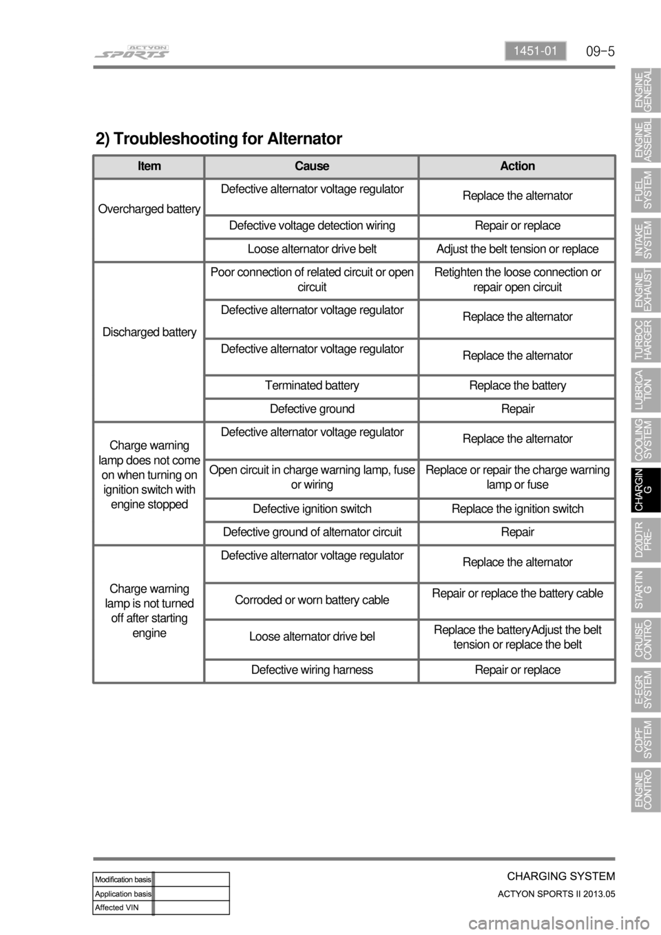
2) Troubleshooting for Alternator
Item Cause Action
Overcharged batteryDefective alternator voltage regulator
Replace the alternator
Defective voltage detection wiring Repair or replace
Loose alternator drive belt Adjust the belt tension or replace
Discharged batteryPoor connection of related circuit or open
circuitRetighten the loose connection or
repair open circuit
Defective alternator voltage regulator
Replace the alternator
Defective alternator voltage regulator
Replace the alternator
Terminated battery Replace the battery
Defective ground Repair
Charge warning
lamp does not come
on when turning on
ignition switch with
engine stoppedDefective alternator voltage regulator
Replace the alternator
Open circuit in charge warning lamp, fuse
or wiringReplace or repair the charge warning
lamp or fuse
Defective ignition switch Replace the ignition switch
Defective ground of alternator circuit Repair
Charge warning
lamp is not turned
off after starting
engineDefective alternator voltage regulator
Replace the alternator
Corroded or worn battery cableRepair or replace the battery cable
Loose alternator drive belReplace the batteryAdjust the belt
tension or replace the belt
Defective wiring harness Repair or replace
Page 154 of 751
09-91451-01
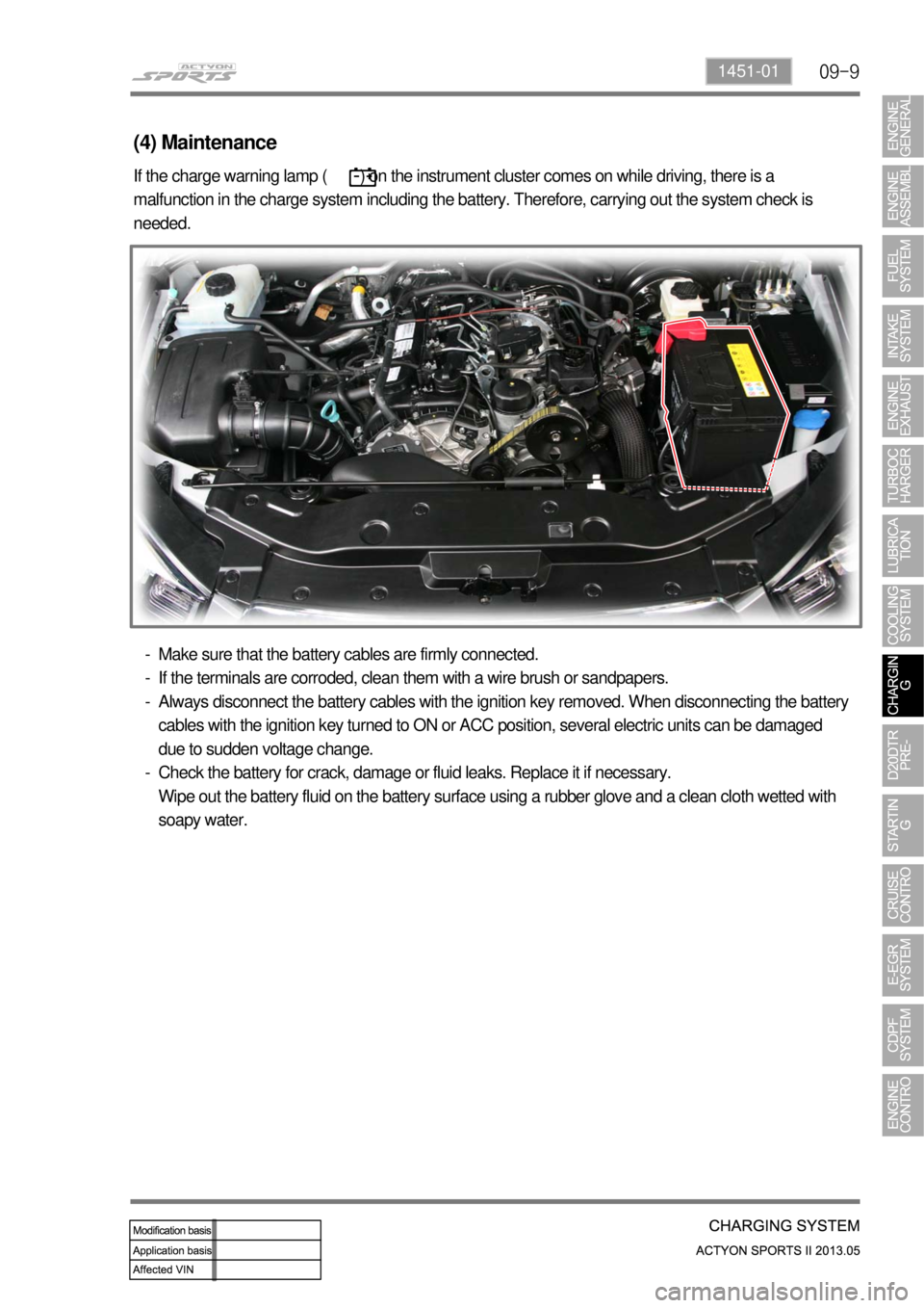
If the charge warning lamp ( ) on the instrument cluster comes on while driving, there is a
malfunction in the charge system including the battery. Therefore, carrying out the system check is
needed.
(4) Maintenance
Make sure that the battery cables are firmly connected.
If the terminals are corroded, clean them with a wire brush or sandpapers.
Always disconnect the battery cables with the ignition key removed. When disconnecting the battery
cables with the ignition key turned to ON or ACC position, several electric units can be damaged
due to sudden voltage change.
Check the battery for crack, damage or fluid leaks. Replace it if necessary.
Wipe out the battery fluid on the battery surface using a rubber glove and a clean cloth wetted with
soapy water. -
-
-
-
Page 188 of 751
14-4
2. CAUTIONS
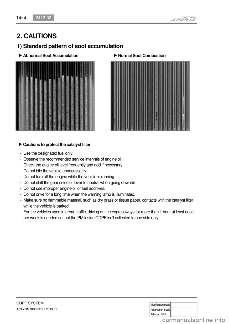
1) Standard pattern of soot accumulation
Abnormal Soot Accumulation ▶
Normal Soot Combustion ▶
Cautions to protect the catalyst filter ▶
Use the designated fuel only.
Observe the recommended service intervals of engine oil.
Check the engine oil level frequently and add if necessary.
Do not idle the vehicle unnecessarily.
Do not turn off the engine while the vehicle is running.
Do not shift the gear selector lever to neutral when going downhill.
Do not use improper engine oil or fuel additives.
Do not drive for a long time when the warning lamp is illuminated.
Make sure no flammable material, such as dry grass or tissue paper, contacts with the catalyst filter
while the vehicle is parked.
For the vehicles used in urban traffic, driving on the expressways for more than 1 hour at least once
per week is needed so that the PM inside CDPF isn't collected to one side only. -
-
-
-
-
-
-
-
-
-
Page 189 of 751
14-52412-02
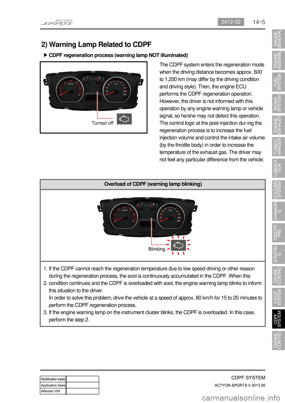
The CDPF system enters the regeneration mode
when the driving distance becomes approx. 600
to 1,200 km (may differ by the driving condition
and driving style). Then, the engine ECU
performs the CDPF regeneration operation.
However, the driver is not informed with this
operation by any engine warning lamp or vehicle
signal, so he/she may not detect this operation.
The control logic at the post-injection dur-ing the
regeneration process is to increase the fuel
injection volume and control the intake air volume
(by the throttle body) in order to increase the
temperature of the exhaust gas. The driver may
not feel any particular difference from the vehicle.
Overload of CDPF (warning lamp blinking)
2) Warning Lamp Related to CDPF
CDPF regeneration process (warning lamp NOT illuminated) ▶
If the CDPF cannot reach the regeneration temperature due to low speed driving or other reason
during the regeneration process, the soot is continuously accumulated in the CDPF. When this
condition continues and the CDPF is overloaded with soot, the engine warning lamp blinks to inform
this situation to the driver.
In order to solve this problem, drive the vehicle at a speed of approx. 80 km/h for 15 to 20 minutes to
perform the CDPF regeneration process.
If the engine warning lamp on the instrument cluster blinks, the CDPF is overloaded. In this case,
perform the step 2. 1.
2.
3.
Page 190 of 751

14-6
Excessive overload of CDPF (warning lamp illuminated)
If the vehicle is driven at a speed of 5 to 10 km/h for an extended period of time, the soot
accumulated in the CDPF cannot be burned as the CDPF cannot reach the regeneration
temperature. Then, an excessive amount of soot can be accumulated in the CDPF.
This case is much worse than the simple over-load of the CDPF. To inform this to the driver, the
engine warning lamp comes on and the engine power is decreased to protect the system.
To solve this problem, blow soot between the engine and exhaust system several times and erase
the related DTC. Then, check if the same DTC is regenerated again. If so, check the DTC related to
the differential pressure sensor. 1.
2.
3.
Page 285 of 751
06-52110-01
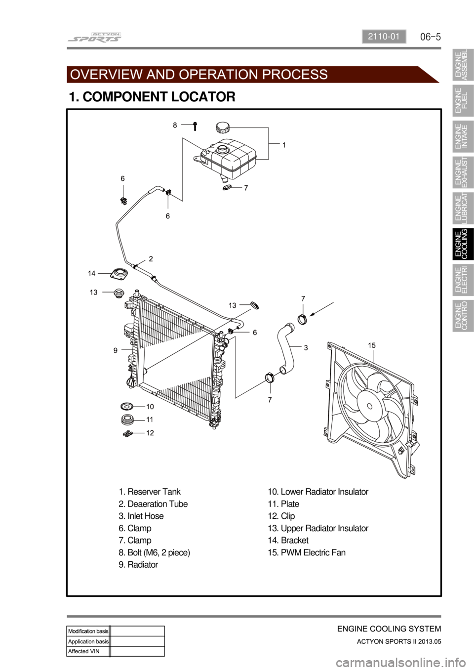
1. COMPONENT LOCATOR
1. Reserver Tank
2. Deaeration Tube
3. Inlet Hose
6. Clamp
7. Clamp
8. Bolt (M6, 2 piece)
9. Radiator10. Lower Radiator Insulator
11. Plate
12. Clip
13. Upper Radiator Insulator
14. Bracket
15. PWM Electric Fan
Page 295 of 751

07-6
(2) Cold Cranking Amperage
The cold cranking amperage test is expressed at a battery temperature of -18°C(0°F).
The current rating is the minimum amperage, which must be maintained by the battery for 30 seconds at
the specified temperature, while meeting a minimum voltage requirement of 7.2 volts.
This rating is a measure of cold cranking capacity.
The battery is not designed to last indefinitely. However, with proper care, the battery will provide many
years of service. If the battery tests well, but fails to perform satisfactorily in service for no apparent
reason, the following factors may point to the cause of the trouble:
Vehicle accessories are left on overnight.
Slow average driving speeds are used for short periods.
The vehicle's electrical load is more than the generator output, particularly with the addition o
f
aftermarket equipment.
Defects in the charging system, such as electrical shorts, a slipping generator belt, a faulty generator,
or a faulty voltage regulator.
Battery abuse, including failure to keep the battery cable terminals clean and tight or a loose battery
hold-down clamp.
Mechanical problems in the electrical system, such as shorted or pinched wires. ·
·
·
·
·
·
3) Charging Time Required
The time required to charge a battery will vary depending upon the following factors:
Size of Battery - A Completely discharged large heavy-duty battery required more than twice the
recharging time as a completely discharged small passenger car battery. ▶
<007b008c00940097008c00990088009b009c0099008c00470054004700680047009300960095008e008c00990047009b00900094008c0047009e00900093009300470089008c00470095008c008c008b008c008b0047009b00960047008a008f0088009900
8e008c00470088009500a0004700890088009b009b008c0099>y at -18°C(0°F) than at
27°C(80°F).
When a fast charger is connected to a cold battery, the current accepted by the battery will be very
low at first.
The battery will accept a higher current rate as the battery warms. ▶
Charger Capacity - A charger which can supply only 5 amperes will require a much longer charging
period than a charger that can supply 30 amperes or more. ▶
State-of-Charge - A completely discharged battery requires more than twice as much charge as a
onehalf charged battery.
Because the electrolyte is nearly pure water and a poor conductor in a completely discharged
battery, the current accepted by the battery is very low at first. Later, as the charging current causes
the electrolyte acid content to increase, the charging current will likewise increase. ▶
Page 297 of 751
07-8
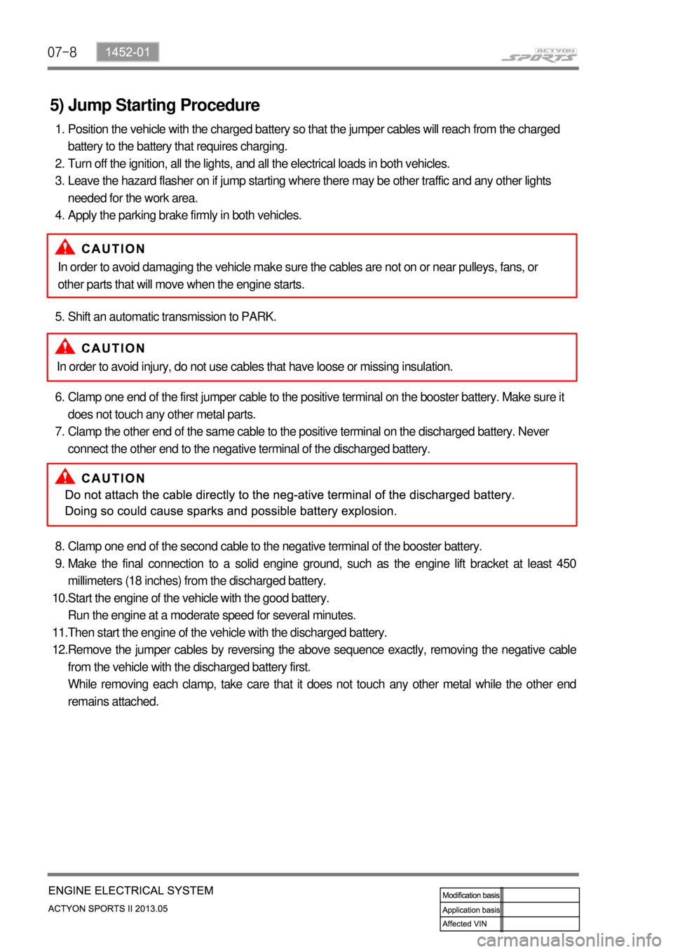
5) Jump Starting Procedure
Position the vehicle with the charged battery so that the jumper cables will reach from the charged
battery to the battery that requires charging.
Turn off the ignition, all the lights, and all the electrical loads in both vehicles.
Leave the hazard flasher on if jump starting where there may be other traffic and any other lights
needed for the work area.
Apply the parking brake firmly in both vehicles. 1.
2.
3.
4.
Shift an automatic transmission to PARK. 5.
Clamp one end of the first jumper cable to the positive terminal on the booster battery. Make sure it
does not touch any other metal parts.
Clamp the other end of the same cable to the positive terminal on the discharged battery. Never
connect the other end to the negative terminal of the discharged battery. 6.
7.
Clamp one end of the second cable to the negative terminal of the booster battery.
Make the final connection to a solid engine ground, such as the engine lift bracket at least 450
millimeters (18 inches) from the discharged battery.
Start the engine of the vehicle with the good battery.
Run the engine at a moderate speed for several minutes.
Then start the engine of the vehicle with the discharged battery.
Remove the jumper cables by reversing the above sequence exactly, removing the negative cable
from the vehicle with the discharged battery first.
While removing each clamp, take care that it does not touch any other metal while the other end
remains attached. 8.
9.
10.
11.
12.In order to avoid damaging the vehicle make sure the cables are not on or near pulleys, fans, or
other parts that will move when the engine starts.
In order to avoid injury, do not use cables that have loose or missing insulation.