lamp SSANGYONG NEW ACTYON SPORTS 2013 Service Manual
[x] Cancel search | Manufacturer: SSANGYONG, Model Year: 2013, Model line: NEW ACTYON SPORTS, Model: SSANGYONG NEW ACTYON SPORTS 2013Pages: 751, PDF Size: 72.63 MB
Page 2 of 751
01-4
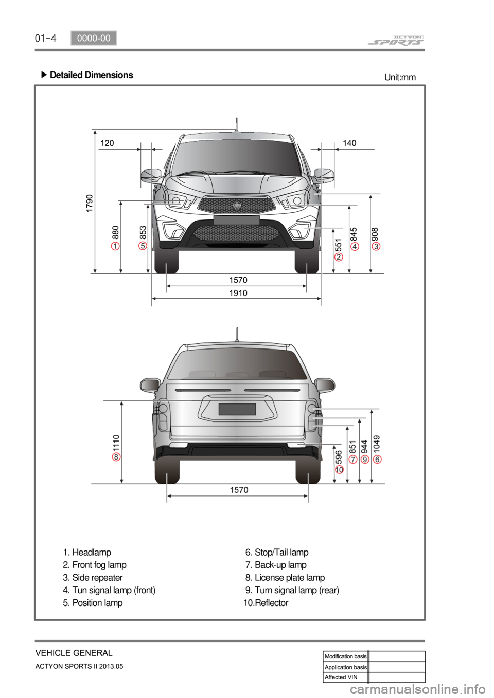
Detailed Dimensions ▶
Unit:mm
Headlamp
Front fog lamp
Side repeater
Tun signal lamp (front)
Position lamp 1.
2.
3.
4.
5.Stop/Tail lamp
Back-up lamp
License plate lamp
Turn signal lamp (rear)
Reflector 6.
7.
8.
9.
10.
Page 30 of 751
01-130000-00
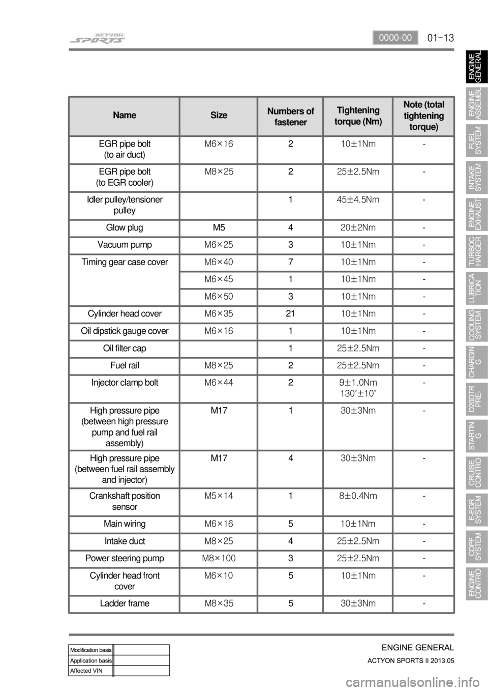
NameSizeNumbers of
fastener Tightening
torque (Nm) Note (total
tightening torque)
Idler pulley/tensioner pulley 1
45±4.5Nm -
Glow plug M5 4 20±2Nm -
Vacuum pump M6×25 3 10±1Nm -
Timing gear case cover M6×40 7 10±1Nm -
M6×45 1 10±1Nm -
M6×50 3 10±1Nm -
Cylinder head cover M6×35 21 10±1Nm -
Oil dipstick gauge cover M6×16 1 10±1Nm -
Oil filter cap 1 25±2.5Nm -
Fuel rail M8×25 2 25±2.5Nm -
Injector clamp bolt M6×44 2 9±1.0Nm
130˚±10˚ -
High pressure pipe
(between high pressure pump and fuel rail assembly) M17 1
30±3Nm -
High pressure pipe
(between fuel rail assembly and injector) M17 4
30±3Nm -
Crankshaft position sensor M5×14
1 8±0.4Nm -
Main wiring M6×16 5 10±1Nm -
Intake duct M8×25 425±2.5Nm -
Power steering pump M8×100 3 25±2.5Nm -
Cylinder head front cover M6×10
5 10±1Nm -
Ladder frame M8×355 30±3Nm
-
EGR pipe bolt
(to air duct) M6×16
2 10±1Nm -
EGR pipe bolt
(to EGR cooler) M8×25
225±2.5Nm -
Page 37 of 751
02-6
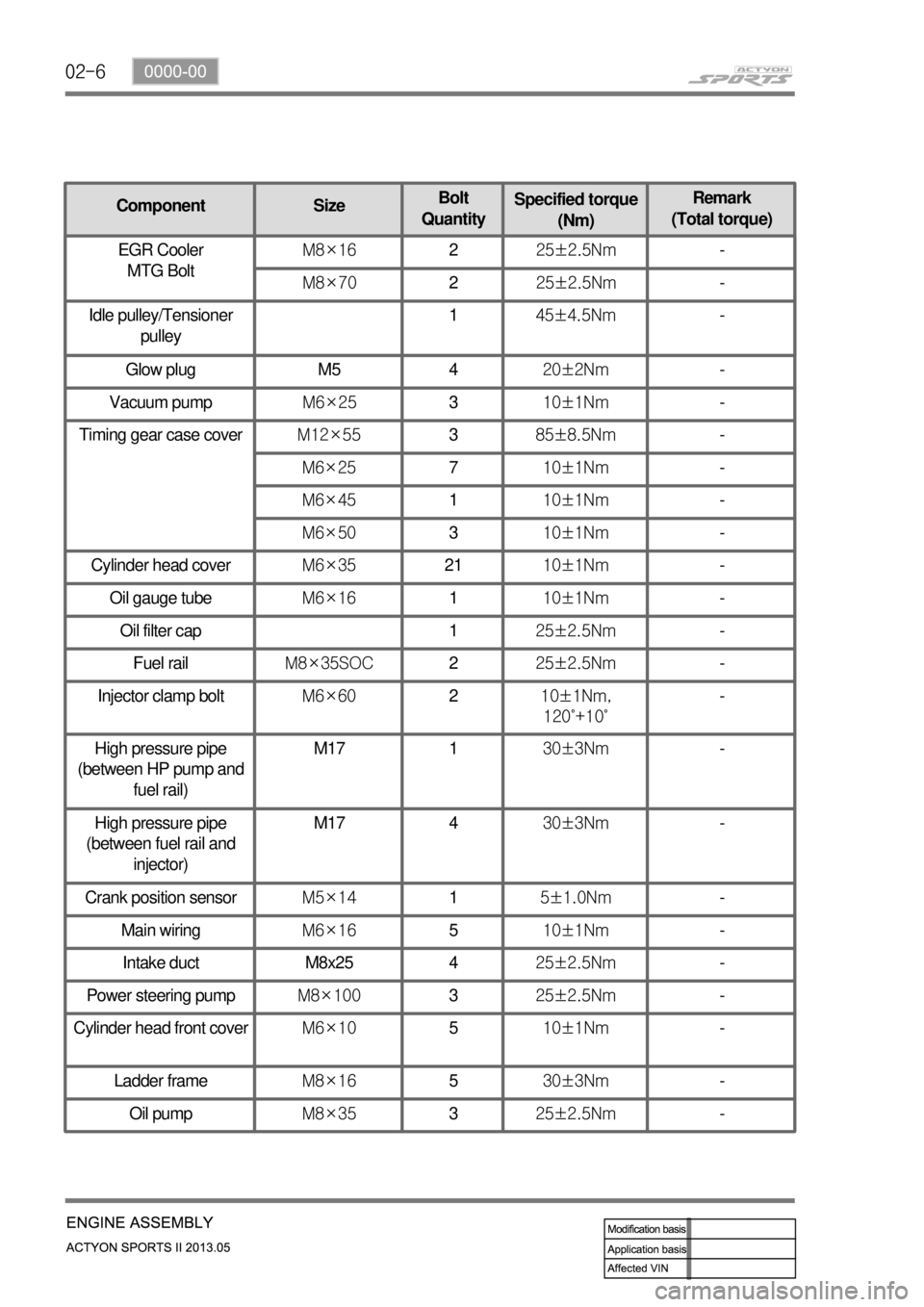
ComponentSizeBolt
Quantity Specified torque
(Nm) Remark
(Total torque)
Glow plug M5 4 20±2Nm -
Vacuum pump M6×253 10±1Nm -
Timing gear case cover M12×55 3 85±8.5Nm -
M6×25 7 10±1Nm -
M6×45 1 10±1Nm -
M6×50 3 10±1Nm -
Cylinder head cover M6×35 21 10±1Nm -
Oil gauge tube M6×16 1 10±1Nm -
Oil filter cap 1 25±2.5Nm -
Fuel rail M8×35SOC 2 25±2.5Nm -
Injector clamp bolt M6×60 2 10±1Nm,
120˚+10˚ -
High pressure pipe
(between HP pump and fuel rail) M17 1
30±3Nm -
High pressure pipe
(between fuel rail and injector) M17 4
30±3Nm -
Crank position sensor M5×14 1 5±1.0Nm -
Main wiring M6×16 5 10±1Nm -
Intake duct M8x25 4 25±2.5Nm -
Power steering pump M8×100 3 25±2.5Nm -
Cylinder head front cover M6×10 5 10±1Nm -
Ladder frame M8×16 5 30±3Nm -
Oil pump M8×35 3 25±2.5Nm -
EGR Cooler
MTG Bolt M8×16
225±2.5Nm -
M8×70 225±2.5Nm -
Idle pulley/Tensioner pulley 1
45±4.5Nm -
Page 60 of 751
02-290000-00
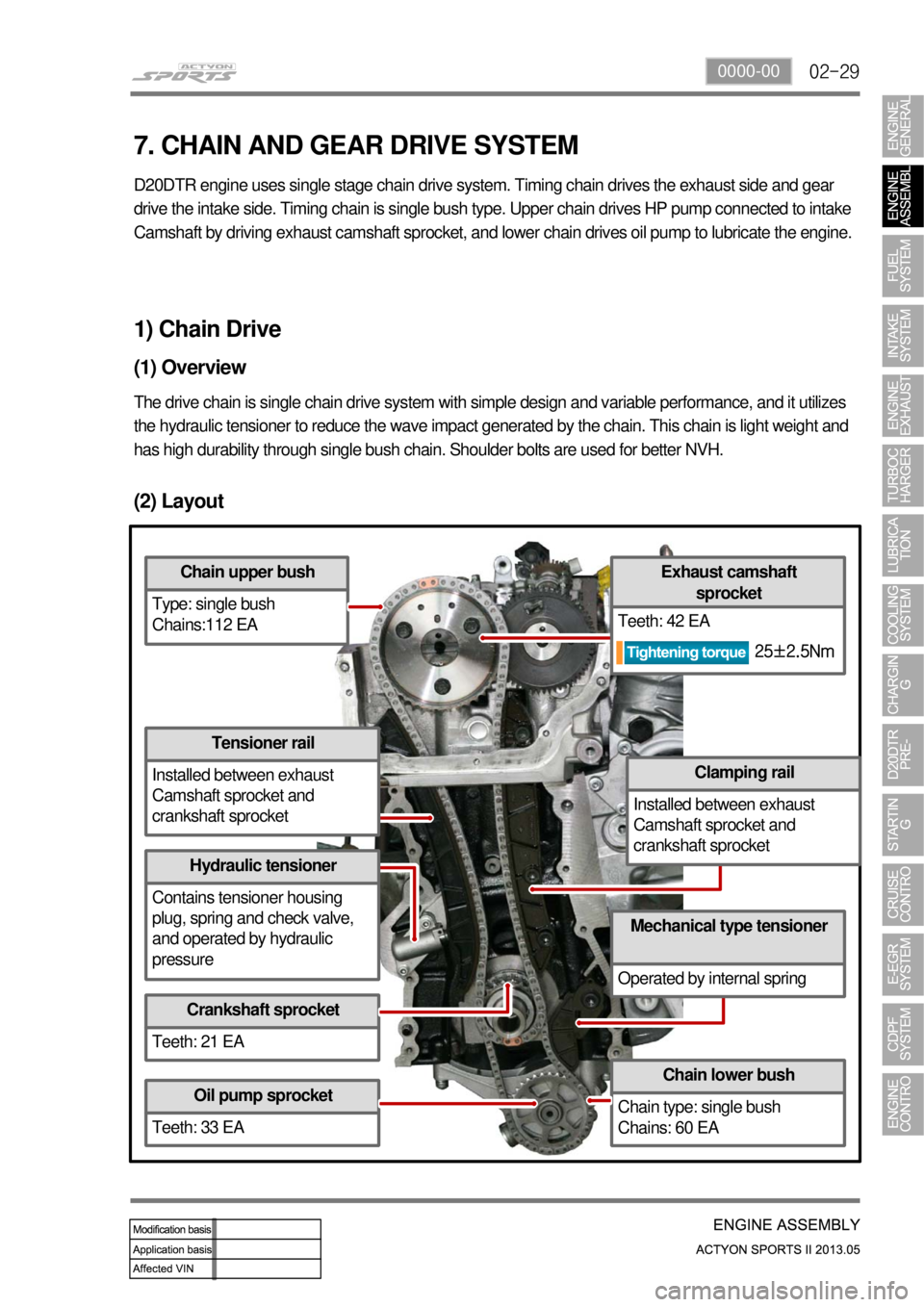
(2) Layout
Chain upper bush
Type: single bush
Chains:112 EA
Tensioner rail
Installed between exhaust
Camshaft sprocket and
crankshaft sprocket
Hydraulic tensioner
Contains tensioner housing
plug, spring and check valve,
and operated by hydraulic
pressure
Crankshaft sprocket
Teeth: 21 EA
Oil pump sprocket
Teeth: 33 EA
Chain lower bush
Chain type: single bush
Chains: 60 EA
Mechanical type tensioner
Operated by internal spring
Clamping rail
Installed between exhaust
Camshaft sprocket and
crankshaft sprocket
Exhaust camshaft sprocket
Teeth: 42 EA
1) Chain Drive
(1) Overview
The drive chain is single chain drive system with simple design and variable performance, and it utilizes
the hydraulic tensioner to reduce the wave impact generated by the chain\
. This chain is light weight and
has high durability through single bush chain. Shoulder bolts are used f\
or better NVH.
7. CHAIN AND GEAR DRIVE SYSTEM
D20DTR engine uses single stage chain drive system. Timing chain drives the exhaust side and gear
drive the intake side. Timing chain is single bush ty pe. Upper chain drives HP pump connected to intake
Camshaft by driving exhaust camshaft sprocket, and lowe r chain drives oil pump to lubricate the engine.
25±2.5Nm
Page 62 of 751
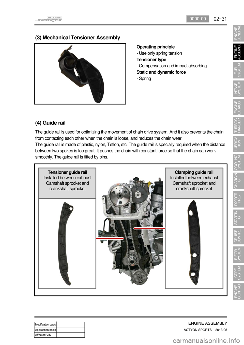
02-310000-00
Clamping guide rail
Installed between exhaust
Camshaft sprocket and
crankshaft sprocketTensioner guide rail
Installed between exhaust
Camshaft sprocket and
crankshaft sprocket
(3) Mechanical Tensioner Assembly
Operating principle
- Use only spring tension
Tensioner type
- Compensation and impact absorbing
Static and dynamic force
- Spring
(4) Guide rail
The guide rail is used for optimizing the movement of chain drive system. And it also prevents the chain
from contacting each other when the chain is loose, and reduces the chain wear.
The guide rail is made of plastic, nylon, Teflon, etc. The guide rail is specially required when the distance
between two spokes is too great. It pushes the chain with constant force so that the chain can work
smoothly. The guide rail is fitted by pins.
Page 95 of 751
03-18
3. CAUTIONS FOR DI ENGINE
1) Cautions for DI Engine
This chapter describes the cautions for DI engine equipped vehicle. This includes the water separation
from engine, warning lights, symptoms when engine malfunctioning, causes and actions.
DI Engine 1.
Comparatively conventional diesel engines, DI engine controls the fuel injection and timing electrically,
delivers high power and reduces less emission..
System Safety Mode 2.
When a severe failure has been occurred in a vehicle, the system safety mode is activated to protect the
system. It reduces the driving force, restricts the engine speed (rpm) and stops engine operation. Refer
to "Diagnosis" section in this manual.
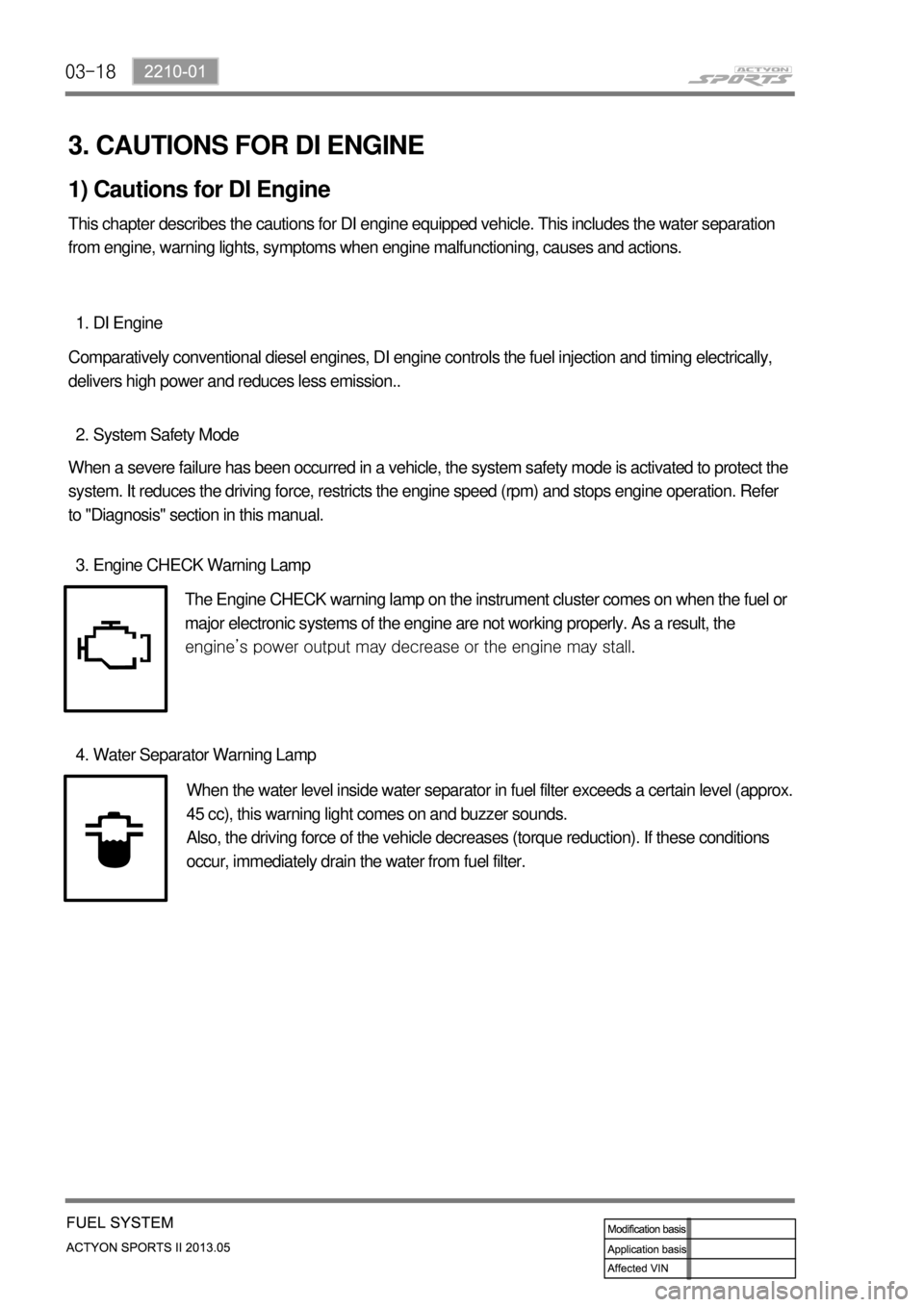
Engine CHECK Warning Lamp 3.
The Engine CHECK warning lamp on the instrument cluster comes on when the fuel or
major electronic systems of the engine are not working properly. As a result, the
<008c0095008e00900095008c02c5009a004700970096009e008c009900470096009c009b0097009c009b00470094008800a00047008b008c008a0099008c0088009a008c0047009600990047009b008f008c0047008c0095008e00900095008c0047009400
8800a00047009a009b0088009300930055>
Water Separator Warning Lamp 4.
When the water level inside water separator in fuel filter exceeds a certain level (approx.
45 cc), this warning light comes on and buzzer sounds.
Also, the driving force of the vehicle decreases (torque reduction). If these conditions
occur, immediately drain the water from fuel filter.
Page 97 of 751
03-20
(2) Di engine and its expected problems and remedies can be caused by
water in fuel
System supplement against paraffin separation ▶
In case of Diesel fuel, paraffin, one of the elements, can be separated from fuel during winter and then
can stick on the fuel filter blocking fuel flow and causing difficult starting finally. Oil companies supply
summer fuel and winter fuel by differentiating mixing ratio of kerosene and other elements by region and
season. However, above phenomenon can be happened if stations have poor facilities or sell improper
fuel for the season. In case of DI engine, purity of fuel is very important factor to keep internal
preciseness of HP pump and injector.
Accordingly, more dense mesh than conventional fuel filter is used. To prevent fuel filter internal clogging
due to paraffin separation, SYMC is using fuel line that high pressure and temperature fuel injected by
injector returns through fuel filter to have an effect of built-in heater (see fuel system).
System supplement and remedy against water in fuel ▶
As mentioned above, some gas stations supply fuel with excessive than specified water. In the
conventional IDI engine, excessive water in the fuel only causes dropping engine power or engine
hunting. However, fuel system in the DI engine consists of precise components so water in the fuel can
cause malfunctions of HP pump due to poor lubrication of pump caused by poor coating film during high
speed pumping and bacterization (under long period parking). To prevent problems can be caused by
excessive water in fuel, water separator is installed inside of fuel filter. When fuel is passing filter, water
that has relatively bigger specific gravity is accumulated on the bottom of the filter.
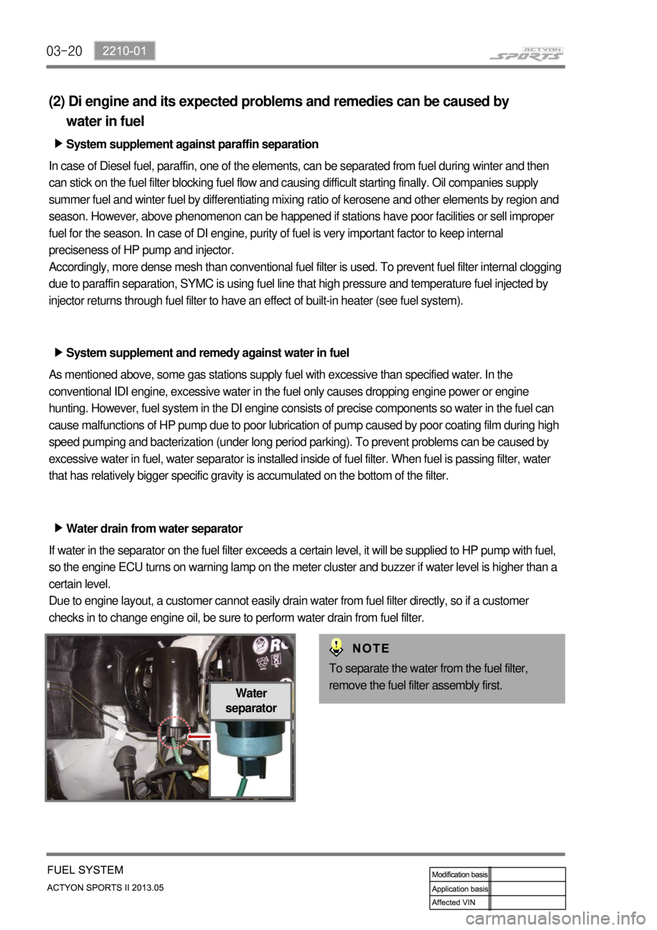
Water drain from water separator ▶
If water in the separator on the fuel filter exceeds a certain level, it will be supplied to HP pump with fuel,
so the engine ECU turns on warning lamp on the meter cluster and buzzer if water level is higher than a
certain level.
Due to engine layout, a customer cannot easily drain water from fuel filter directly, so if a customer
checks in to change engine oil, be sure to perform water drain from fuel filter.
Water
separator
To separate the water from the fuel filter,
remove the fuel filter assembly first.
Page 106 of 751
04-51719-00
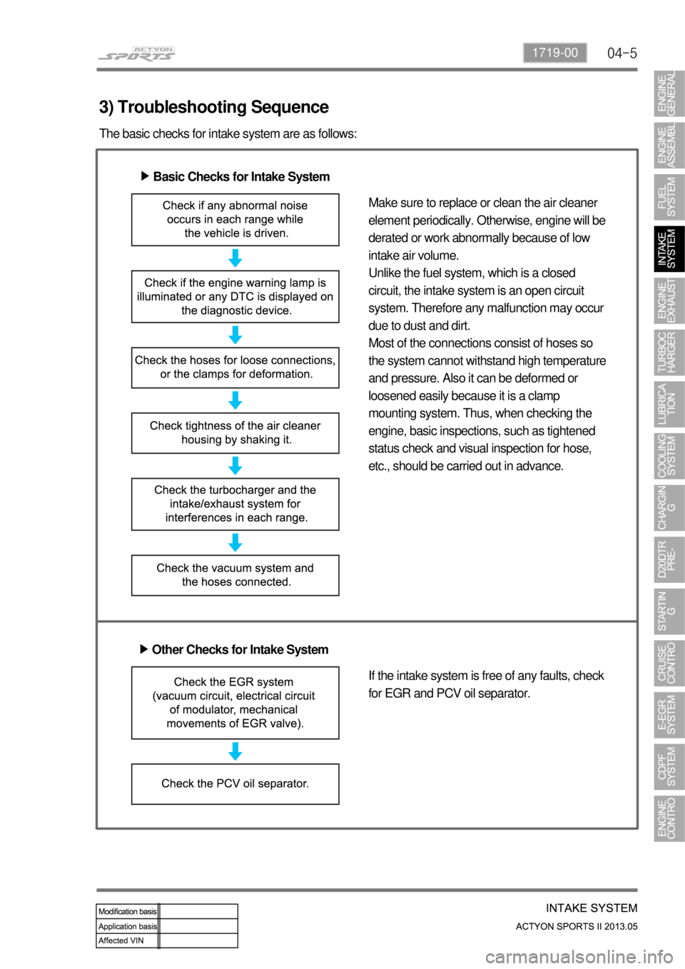
3) Troubleshooting Sequence
The basic checks for intake system are as follows:
Basic Checks for Intake System ▶
Make sure to replace or clean the air cleaner
element periodically. Otherwise, engine will be
derated or work abnormally because of low
intake air volume.
Unlike the fuel system, which is a closed
circuit, the intake system is an open circuit
system. Therefore any malfunction may occur
due to dust and dirt.
Most of the connections consist of hoses so
the system cannot withstand high temperature
and pressure. Also it can be deformed or
loosened easily because it is a clamp
mounting system. Thus, when checking the
engine, basic inspections, such as tightened
status check and visual inspection for hose,
etc., should be carried out in advance.
Other Checks for Intake System ▶
If the intake system is free of any faults, check
for EGR and PCV oil separator.
Page 119 of 751
06-50000-00
2) Inspection of Turbocharger
When problem occurs with the turbocharger, it could cause engine power decline, excessive discharge of
exhaust gas, outbreak of abnormal noise and excessive consumption of oil.
On-board Inspection 1.
Check the bolts and nuts foe looseness or missing
Check the intake and exhaust manifold for looseness or damage
Check the oil supply pipe and drain pipe for damages
Check the housing for crack and deterioration -
-
-
-
Inspection of turbine 2.
Remove the exhaust pipe at the opening of the turbine and check, with a lamp, the existence of
interference of housing and wheel, oil leakage and contamination (at blade edge) of foreign materials.
Interference: In case where the oil leak sign exists, even the small traces of interferences on the
turbine wheel mean, most of times, that abrasion has occurred on the journal bearing. Must inspect
after overhauling the turbocharger.
Oil Leakage: Followings are the reasons for oil leakage condition -
-
Idling for long period of time can cause oil leakage to the turbine side due to low pressure of exhaust
gas and the rotation speed of turbine wheel. Please note this is not a turbocharger problem.
Oil Drain Pipe Defect
In case where oil flow from the turbocharger sensor housing to the crank case is not smooth would
become the reason for leakage as oil builds up within the center housing. Also, oil thickens (sludge) at
high temperature and becomes the indirect reason of wheel hub section. In such case, clogging and
damage of the oil drain pipe and the pressure of blow-by gas within the crank case must be inspected.
Damages due to Foreign Materials
When the foreign materials get into the system, it could induce inner damage as rotating balance of
the turbocharger gets out of alignment. -
-Problems in engine: In case where the oil is smeared on inner wall section of the exhaust gas
opening.
Problems in turbocharger: In case where the oil is smeared on only at the exhaust gas
outlet section. *
*
Page 139 of 751
07-51543-00
1. SYSTEM DESCRIPTION
1) Overview
The lubrication system supplies oil to each lubrication section to prevent friction and wear and to remove
heat from the friction part. As the engine runs, frictional heat is generated on each lubrication section. If
this condition persists, the bearing can be burned and stuck.
In other words, it creates an oil film on each sliding surface to convert solid friction to liquid friction in order
to minimize wear and prevent temperature increasing on the friction part.
For the D20DTF engine with no oil pressure switch, the engine ECU receives the low engine oil level
signal from the oil level sensor and communicates with the instrument cluster through the CAN
communication to turn on the warning lamp.
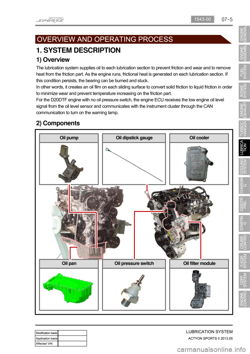
2) Components
Oil coolerOil dipstick gaugeOil pump
Oil filter moduleOil pressure switchOil pan