lamp SSANGYONG NEW ACTYON SPORTS 2013 Owner's Manual
[x] Cancel search | Manufacturer: SSANGYONG, Model Year: 2013, Model line: NEW ACTYON SPORTS, Model: SSANGYONG NEW ACTYON SPORTS 2013Pages: 751, PDF Size: 72.63 MB
Page 298 of 751

07-91452-01
6) Alternator
Alternators are equipped with internal regulators.
Unlike three-wire generators, the alternator may be used with only two connections: battery positive and
an "D+" terminal to the charge indicator lamp.
As with other charging systems, the charge indicator lamp lights when the ignition switch is turned to
RUN, and goes out when the engine is running.
If the charge idicator is on with the engine running, a charging system defect is indicated. This indicato
r
light will glow at full brilliance for several kinds of defects as well as when the system voltage is too high
or too low.
The regulator voltage setting varies with temperature and limits the system voltage by controlling roto
r
field current.
Achieve correct average field current for proper system voltage control by varying the on-off time. At high
speeds, the on-time may be 10 percent and the off-time 90 percent.
At low speeds, with high electrical loads, the on-time may be 90 percent and the off-time 10 percent.
7) Charging System
Generators use a new type of regulator that incorporates a diode trio.
A Delta stator, a rectifier bridge, and a rotor with slip rings and brushes are electrically similar
to earlier generators.
A conventional pulley and fan are used.
There is no test hole.
8) Starter
Wound field starter motors have pole pieces, arranged around the armature, which are energized by
wound field coils.
Enclosed shift lever cranking motors have the shift lever mechanism and the solenoid plunger enclosed
in the drive housing, protecting them from exposure to dirt, icy conditions, and splashes.
In the basic circuit, solenoid windings are energized when the switch is closed.
The resulting plunger and shift lever movement causes the pinion to engage the engine flywheel ring
gear.
The solenoid main contacts close. Cranking then takes place.
When the engine starts, pinion overrun protects the armature from excessive speed until the switch is
opened, at which time the return spring causes the pinion to disengage.
To prevent excessive overrun, the switch should be released immediately after the engine starts.
Page 304 of 751

01-58410-02
ICM
Interior Fuse & Relay
Box (RH)
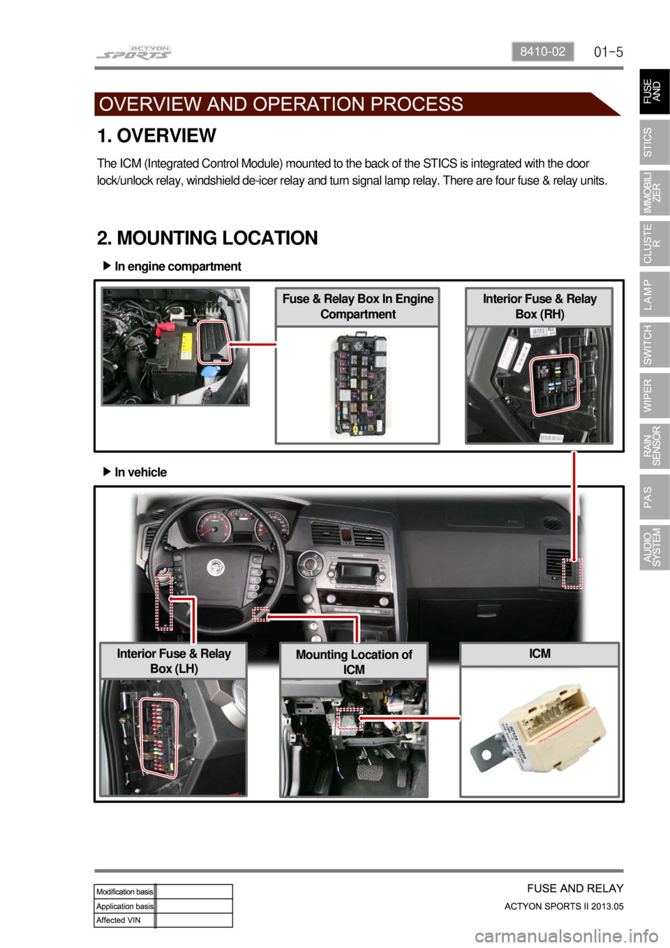
2. MOUNTING LOCATION
In engine compartment ▶
In vehicle ▶
Fuse & Relay Box In Engine
Compartment
1. OVERVIEW
The ICM (Integrated Control Module) mounted to the back of the STICS is integrated with the door
lock/unlock relay, windshield de-icer relay and turn signal lamp relay. There are four fuse & relay units.
Interior Fuse & Relay
Box (LH)Mounting Location of
ICM
Page 308 of 751

01-98410-02
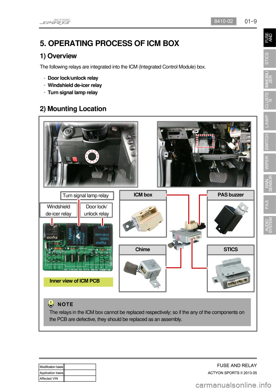
5. OPERATING PROCESS OF ICM BOX
The following relays are integrated into the ICM (Integrated Control Module) box.
Door lock/unlock relay
Windshield de-icer relay
Turn signal lamp relay -
-
-
1) Overview
2) Mounting Location
Door lock/
unlock relay
Turn signal lamp relay
Windshield
de-icer relay
Inner view of ICM PCB
PAS buzzer
Chime
ICM box
STICS
The relays in the ICM box cannot be replaced respectively; so if the any of the components on
the PCB are defective, they should be replaced as an assembly.
Page 311 of 751

01-12
(3) Turn signal lamp (Hazard warning lamp operation)
The B+ power supplied through the No. F66 interior fuse on the right-hand of the engine compartment is
on standby on the No. 30 and 86 hazard warning lamp relay terminals via the ICM No. 18 terminal.
The STICS activates and/or controls the hazard warning lamp relay using the No. A26 terminal
depending on the operating conditions. The activated relay supplies the No. 87 and 87a terminals with
the power, which is on standby on the No. 30 hazard warning lamp relay terminal.
The supplied power flows to the corresponding circuit via the No. 7 and 16 ICM terminals.
Page 312 of 751

01-138410-02
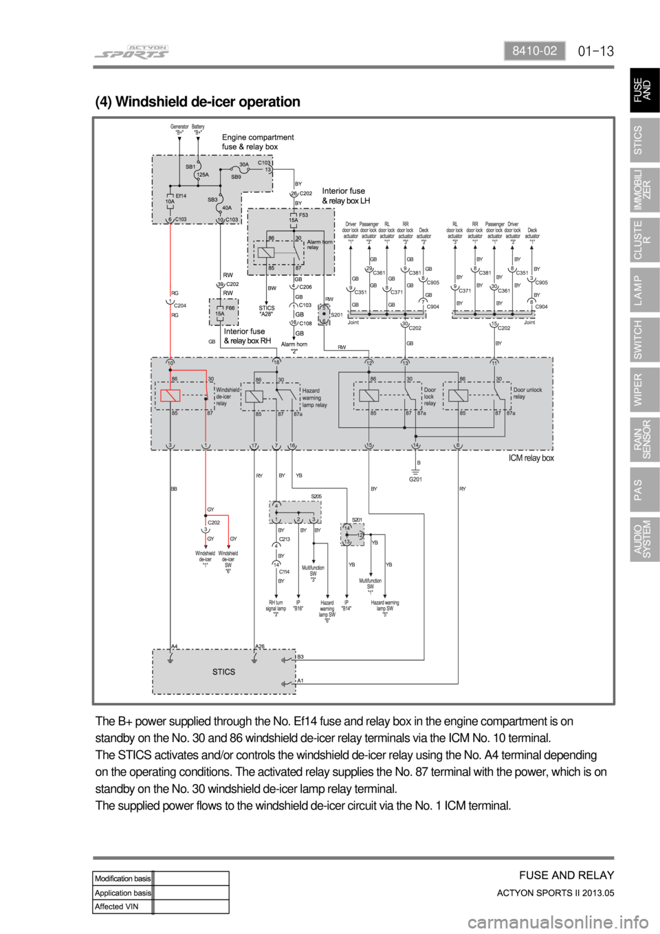
(4) Windshield de-icer operation
The B+ power supplied through the No. Ef14 fuse and relay box in the engine compartment is on
standby on the No. 30 and 86 windshield de-icer relay terminals via the ICM No. 10 terminal.
The STICS activates and/or controls the windshield de-icer relay using the No. A4 terminal depending
on the operating conditions. The activated relay supplies the No. 87 terminal with the power, which is on
standby on the No. 30 windshield de-icer lamp relay terminal.
The supplied power flows to the windshield de-icer circuit via the No. 1 ICM terminal.
Page 313 of 751

02-38710-01
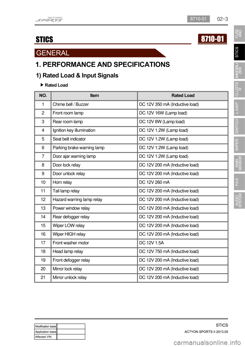
1. PERFORMANCE AND SPECIFICATIONS
1) Rated Load & Input Signals
Rated Load
▶
NO.
Item Rated Load
1 Chime bell / Buzzer DC 12V 350 mA (Inductive load)
2 Front room lamp DC 12V 16W (Lamp load)
3 Rear room lamp DC 12V 8W (Lamp load)
4 Ignition key illumination DC 12V 1.2W (Lamp load)
5 Seat belt indicator DC 12V 1.2W (Lamp load)
6 Parking brake warning lamp DC 12V 1.2W (Lamp load)
7 Door ajar warning lamp DC 12V 1.2W (Lamp load)
8 Door lock relay DC 12V 200 mA (Inductive load)
9 Door unlock relay DC 12V 200 mA (Inductive load)
10 Horn relay DC 12V 260 mA
11 Tail lamp relay DC 12V 200 mA (Inductive load)
12 Hazard warning lamp relay DC 12V 200 mA (Inductive load)
13 Power window relay DC 12V 200 mA (Inductive load)
14 Rear defogger relay DC 12V 200 mA (Inductive load)
15 Wiper LOW relay DC 12V 200 mA (Inductive load)
16 Wiper HIGH relay DC 12V 200 mA (Inductive load)
17 Front washer motor DC 12V 1.5A
18 Head lamp relay DC 12V 750 mA (Inductive load)
19 Front defogger relay DC 12V 200 mA (Inductive load)
20 Mirror lock relay DC 12V 200 mA (Inductive load)
21 Mirror unlock relay DC 12V 200 mA (Inductive load)
Page 315 of 751

02-58710-01
NO.Input Signal Name Logic Status
27 Central door lock switch ON = GND, OFF = OPEN
28 Multifunction auto light switch ON = GND, OFF = OPEN
29 Turn signal lamp switch ON = BAT/GND, OFF = OPEN
(approx. 5.1 V ~ 9.2 V)
30 Rain sensor ON = GND (DATA), OFF = BAT
31 Telematics ON = GND (DATA), OFF = BAT
32 Diagnosis ON = GND (DATA), OFF = BAT (KWP2000)
Page 330 of 751

02-20
▶Auto Light ControlThe tail lamps and headlamps can be controlled by the communication with the rain sensor only
when the auto light switch is in "AUTO" position with the ignition switc\
h "ON".
-
Rain detected headlamp: If it rains heavy which requires the highest INT speed (almost LOW),
the headlamps are turned on automatically.
-
Night detected wiping: When the auto light control turns on the headlamp\
s and the rain senso
r
detects the rain, the wiper sensitivity is automat ically increased by one level in comparison with
daytime.
(i.e. the AUTO wiper switch is at the 3rd level, but the wiper operates\
at the 4th level.)
-
Enlarged auto light sensor
Emitter lens
The LED emitting the infrared
rays is installed on the bottom
and the lens guides the infrared
rays to target point.
Auto light sensor (Vertical)
Auto light sensor (Horizon)
Page 333 of 751

02-238710-01
▶Ignition Key Reminder WarningThe chime buzzer sounds continuously when opening the driver's door whil\
e the ignition key is in
ignition switch.
When removing the ignition key or closing the driver's door during chime\
buzzer operation, the
buzzer stops.
This function does not work when the IGN1 switch is in "ON" position.
-
-
-
(The function has priority over the "TAILLAMP ON WARNING".)
Chime Buzzer
PAS buzzer
ICM relay box
STICS
Page 336 of 751

02-26
▶Tail Lamp Left On WarningThe chime buzzer sounds with the interval of 0.8 second when opening the\
driver's door while the
tail lamp is turned on and the ignition key is removed.
The c/buzzer output stops when turning off the tail lamp and closing the\
driver's door.
The system outputs "UNLOCK" signal for 5 seconds when the driver's and p\
assenger's door lock
switch is locked (while the tail lamp is turned on and the driver's doo\
r is open).
This function does not work when the IGN1 switch is in "ON" position.
-
-
-
-