warning SSANGYONG NEW ACTYON SPORTS 2013 Workshop Manual
[x] Cancel search | Manufacturer: SSANGYONG, Model Year: 2013, Model line: NEW ACTYON SPORTS, Model: SSANGYONG NEW ACTYON SPORTS 2013Pages: 751, PDF Size: 72.63 MB
Page 406 of 751
04-238210-01
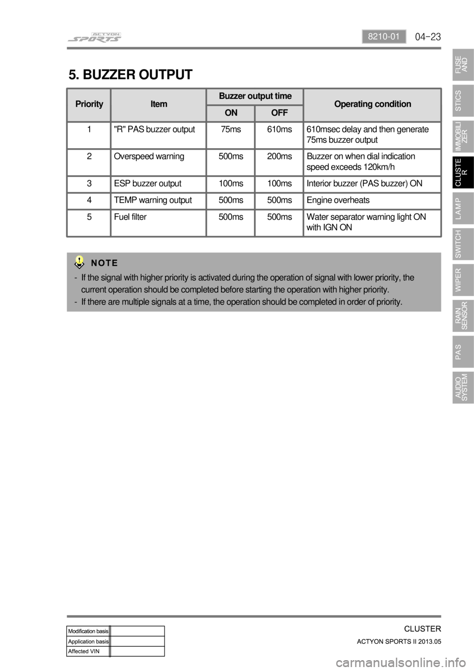
5. BUZZER OUTPUT
Priority ItemBuzzer output time
Operating condition
ON OFF
1 "R" PAS buzzer output 75ms 610ms 610msec delay and then generate
75ms buzzer output
2 Overspeed warning 500ms 200ms Buzzer on when dial indication
speed exceeds 120km/h
3 ESP buzzer output 100ms 100ms Interior buzzer (PAS buzzer) ON
4 TEMP warning output 500ms 500ms Engine overheats
5 Fuel filter 500ms 500ms Water separator warning light ON
with IGN ON
If the signal with higher priority is activated during the operation of signal with lower priority, the
current operation should be completed before starting the operation with higher priority.
If there are multiple signals at a time, the operation should be completed in order of priority. -
-
Page 407 of 751

04-24
6. CIRCUIT DIAGRAM
GAUGE (SPEED, RPM, FUEL, TEMP), WARNING LAMP (FUEL, FUEL FILTER, ABS, BRAKE, 4WD) ▶
Page 408 of 751
04-258210-01
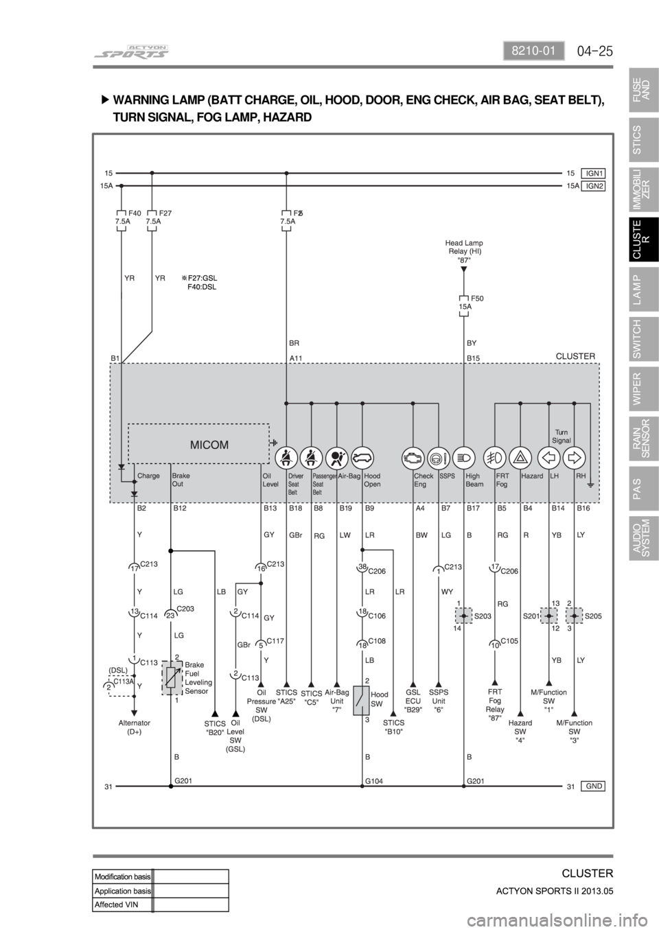
WARNING LAMP (BATT CHARGE, OIL, HOOD, DOOR, ENG CHECK, AIR BAG, SEAT BELT),
TURN SIGNAL, FOG LAMP, HAZARD ▶
Page 410 of 751
06-38610-08
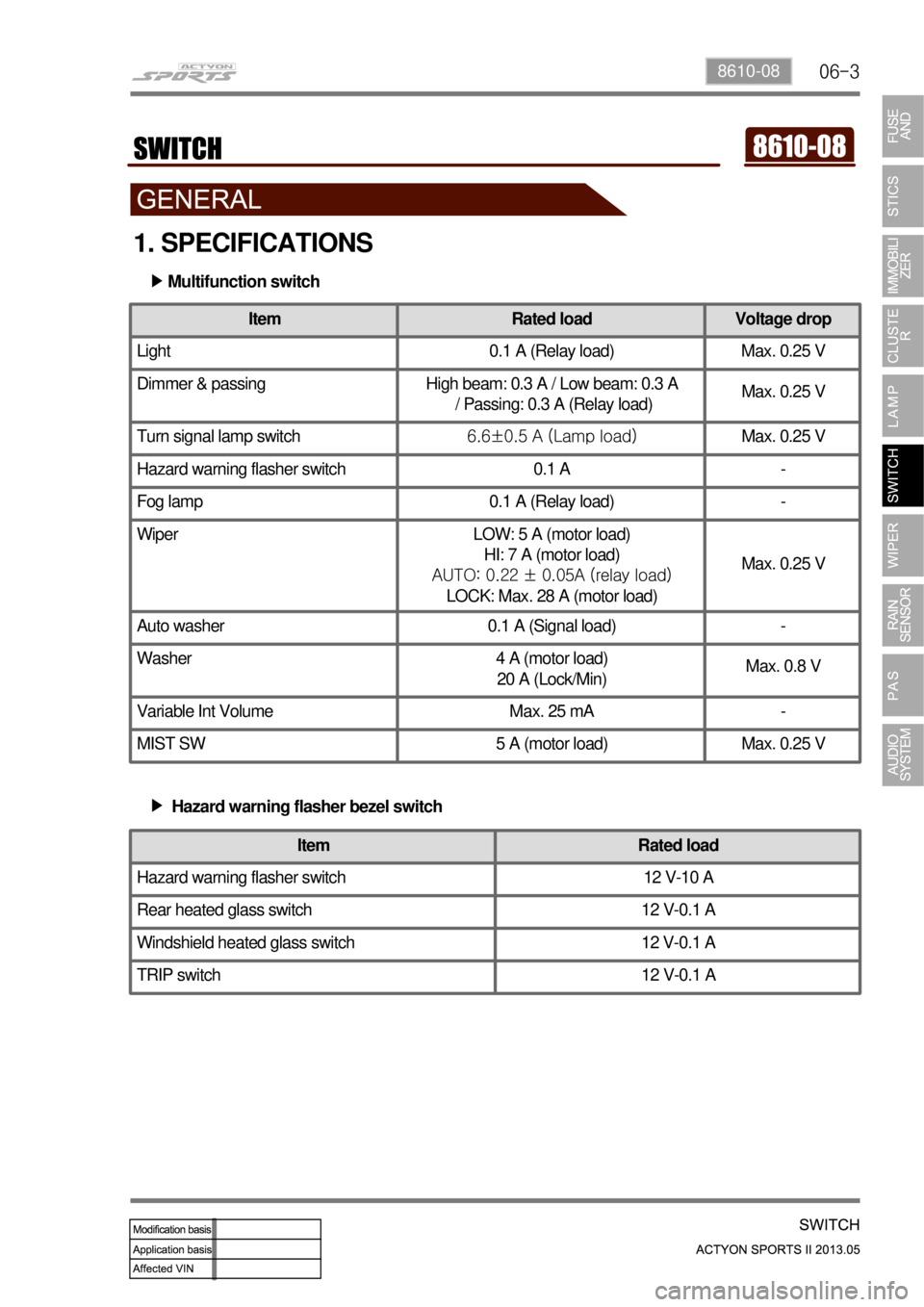
1. SPECIFICATIONS
Multifunction switch ▶
Item Rated load Voltage drop
Light 0.1 A (Relay load) Max. 0.25 V
Dimmer & passing High beam: 0.3 A / Low beam: 0.3 A
/ Passing: 0.3 A (Relay load)Max. 0.25 V
Turn signal lamp switch6.6±0.5 A (Lamp load)Max. 0.25 V
Hazard warning flasher switch 0.1 A -
Fog lamp 0.1 A (Relay load) -
Wiper LOW: 5 A (motor load)
HI: 7 A (motor load)
AUTO: 0.22 ± 0.05A (relay load)
LOCK: Max. 28 A (motor load)Max. 0.25 V
Auto washer 0.1 A (Signal load) -
Washer 4 A (motor load)
20 A (Lock/Min)Max. 0.8 V
Variable Int Volume Max. 25 mA -
MIST SW 5 A (motor load) Max. 0.25 V
Hazard warning flasher bezel switch ▶
Item Rated load
Hazard warning flasher switch 12 V-10 A
Rear heated glass switch 12 V-0.1 A
Windshield heated glass switch 12 V-0.1 A
TRIP switch 12 V-0.1 A
Page 416 of 751
06-98610-08
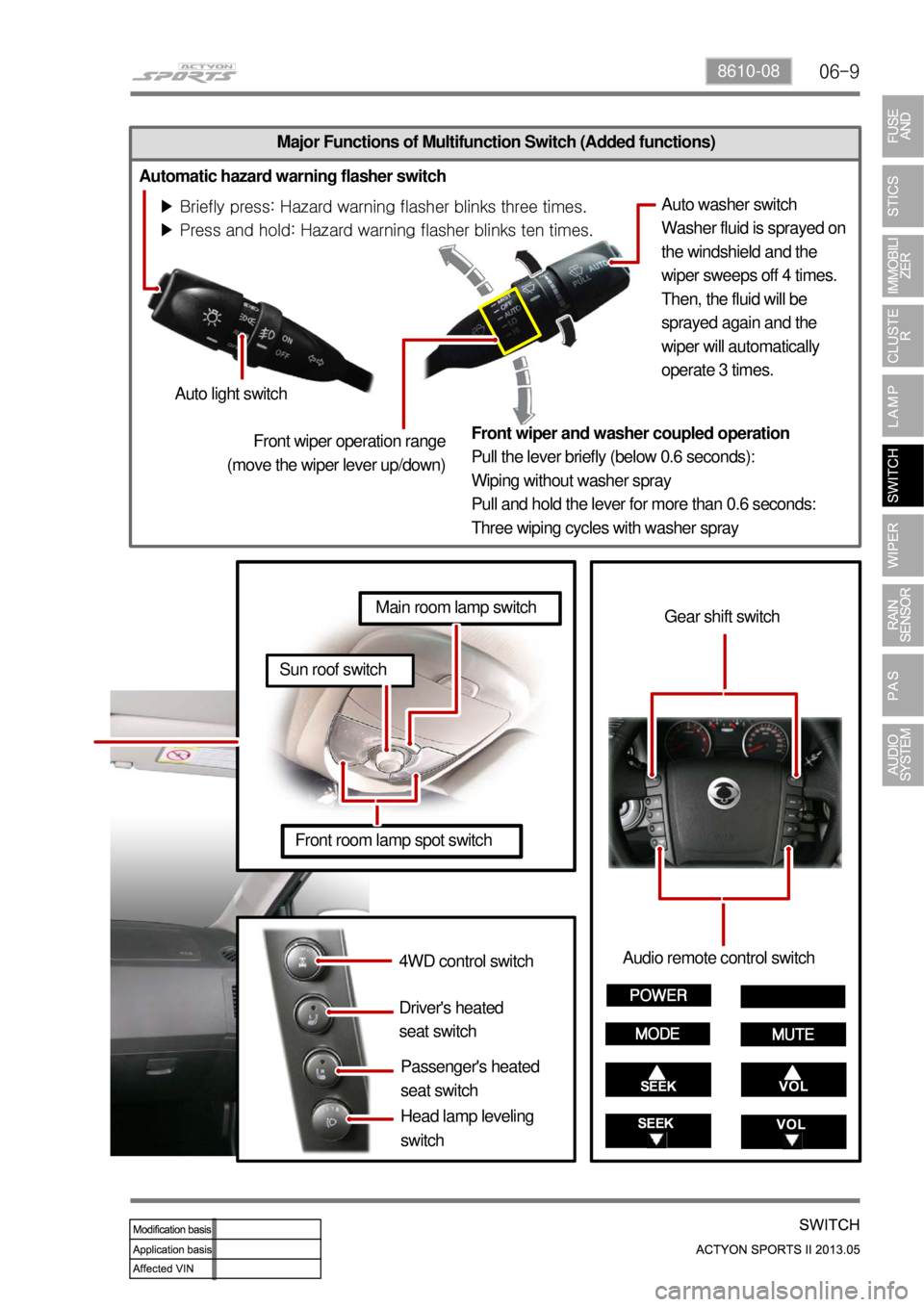
Major Functions of Multifunction Switch (Added functions)
Automatic hazard warning flasher switch
<00470047004700470d960047006900990090008c008d009300a0004700970099008c009a009a00610047006f008800a100880099008b0047009e00880099009500900095008e0047008d00930088009a008f008c0099004700890093009000950092009a00
47009b008f0099008c008c0047009b00900094008c009a0055>
<00470047004700470d96004700770099008c009a009a004700880095008b0047008f00960093008b00610047006f008800a100880099008b0047009e00880099009500900095008e0047008d00930088009a008f008c009900470089009300900095009200
9a0047009b008c00950047009b00900094008c009a0055>Auto washer switch
Washer fluid is sprayed on
the windshield and the
wiper sweeps off 4 times.
Then, the fluid will be
sprayed again and the
wiper will automatically
operate 3 times.
Auto light switch
Front wiper and washer coupled operation
Pull the lever briefly (below 0.6 seconds):
Wiping without washer spray
Pull and hold the lever for more than 0.6 seconds:
Three wiping cycles with washer spray
4WD control switch
Driver's heated
seat switch
Passenger's heated
seat switchAudio remote control switch
Gear shift switch
Front room lamp spot switch
Sun roof switch
Main room lamp switch
Front wiper operation range
(move the wiper lever up/down)
Head lamp leveling
switch
Page 440 of 751

09-6
2. ALARM INTERVAL
While reversing, if obstacles are within stage 1, the warning beep sounds with long intervals. If within
stage 2, the warning beep sounds with short intervals and if within stage 3, the warning beep sounds
continuously.
1) Sensing Distance and Range
Sensor detection range
Within 20 cm from the ground (Intrinsically, supersonic wave sensors may not detect obstacles
within 20 cm from the ground)(Area 1)
Obstacles may not be detected within 80 cm from the sensor(Area 2)
Sensor may not detect zone within 30 cm from the rear bumper (Area 3) -
-
-
Page 441 of 751

09-78790-01
When the ignition switch is in IGN1 position (shift
lever is in "R" position), the sensor will be
diagnosed once. If any malfunction due to an
open circuit in sensor or an error in
sending/receiving signals, the system warns the
driver with audible buzzer sound. If it is normal,
the warning buzzer sounds for 65 ms.
2) Troubleshooting
※ When the sensor failed in self-diagnostics
PAS buzzer
STICS
Page 444 of 751

10-4
2. CAUTIONS AND WARNING FOR SAFETY
Ssangyong is not liable for any personal injury and material damage, caused by violation of traffic
regulations or neglect of observing actual traffic and driving situations.
Colors on display figures in this manual may differ from actual display due to publication concerns. -
-
Do not disassemble or modify this system.
If doing so, it may cause an accident, fire or electric shock.
Do not use the system if it is malfunctioning (sound or video output problem).
Doing so may lead to an accident or electric shock.
Please contact a Ssangyong service dealer immediately.
The system should be used only when the engine is started.
Using the system for an extended period of the with the engine off may discharge the battery.
Do not leave beverages or foreign materials around the system.
If they enter the system, they may cause a fire.
The system may break down if a disc not supported by this system is inserted.
Do not apply impact to or drop this system.
It might cause malfunction.
Never leave the system in a hot or cold place for an extended period of time. Therefore, do not park
<009b008f008c0047009d008c008f0090008a0093008c004700900095004700880047008f0096009b0047009600990047008a00960093008b0047009700930088008a008c00550047007b008f008c00470088009400890090008c0095009b0047009b008c00
940097008c00990088009b009c0099008c0047009a008f0096>uld be -30℃ ~ +80℃ for
proper operation. -
-
-
-
-
-
-
Page 462 of 751
01-16
4. LIMP HOME MODE
In case of transmission malfunction ▶
If a serious fault occurs in the automatic transmission, the TCU enters the limp home mode to
secure safe driving and protect the automatic transmission.
As power is no longer supplied to the solenoid, the current basic function (P, R, N, D) is
maintained and the 4th gear can be maintained only by the operation of the hydraulic system
without electrical operation.
The ECU communicates with other electric modules with CAN. If a serious fault occurs, the
transmission automatically enters the limp home mode for service.
The TCU monitors all factors which can affect to the performance of the transmission and
diagnose the system according to OBD II regulation. 1.
2.
3.
4.
In case of overheated transmission ▶
The TCU enters the limp home mode when the batter voltage drops below 8 V.
If the transmission is overheated, the shift pattern is changed to the hot mode to cool the
transmission more efficiently.
While the transmission is overheated, the selector lever symbol and engine temperature warning
lamp on the instrument cluster blink until the transmission is cooled down to the normal operation
temperature. If the transmission is excessively overheated, the gear cannot be shifted but
remains in the neutral position. 1.
2.
3.
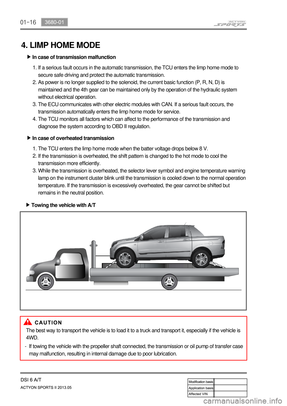
Towing the vehicle with A/T ▶
The best way to transport the vehicle is to load it to a truck and transport it, especially if the vehicle is
4WD.
If towing the vehicle with the propeller shaft connected, the transmission or oil pump of transfer case
may malfunction, resulting in internal damage due to poor lubrication. -
Page 463 of 751
01-173680-01
5. ELECTRONIC CONTROL SYSTEM
1) Overview
The transmission control unit (TCU) and its input/output networks control the operations of transmission:
Shift timing
Line pressure
Clutch pressure (shift feel)
Torque converter clutch -
-
-
-
In addition, the TCU receives input signals from certain transmission-related sensors and switches. The
TCU also uses these signals when determining transmission operating strategy. Using all of these input
signals, the TCU can determine when the time and conditions are right for a shift, or when to apply or
release the torque converter clutch. It will also determine the pressure needed to optimise shift feel. To
accomplish this, the TCU operates six variable bleed control solenoids and four ON/OFF solenoids to
control the operations of transmission.
2) Transmission Control Unit (TCU)
The transmission control unit (TCU) is mounted under the driver's seat and controls the operation of the
transmission.
TCU processes the analog information from the internal sensors and the digital information through CAN
communication lines. TCU monitors all the input and output signals. If there is any failure, TCU changes
the system to “Limp Home Mode” and alerts to the driver through the warning lamp on the
instrument cluster.
(1) Hard-wired (Analog) Input/Output
Input/Output Data between TGS Lever and TCU ▶
Position and conditions of gear select lever
Driving moded (Winter or Standard) -
-
Position of inhibitor switch - Input/Output Data between Inhibitor and TCU ▶
6 control signals for variable bleed solenoid
4 control signals for ON/OFF solenoid
Transmission input speed
Transmission output speed
Transmission oil temperature
EMM (Embeded Memory Module) -
-
-
-
-
- Input/Output Data between Automatic Transmission and TCU ▶
Input/Output Data between Self Diagnostic Connector and TCU ▶
Various DTC codes and TCU information -