check engine SSANGYONG NEW ACTYON SPORTS 2013 Workshop Manual
[x] Cancel search | Manufacturer: SSANGYONG, Model Year: 2013, Model line: NEW ACTYON SPORTS, Model: SSANGYONG NEW ACTYON SPORTS 2013Pages: 751, PDF Size: 72.63 MB
Page 562 of 751
09-134850-01
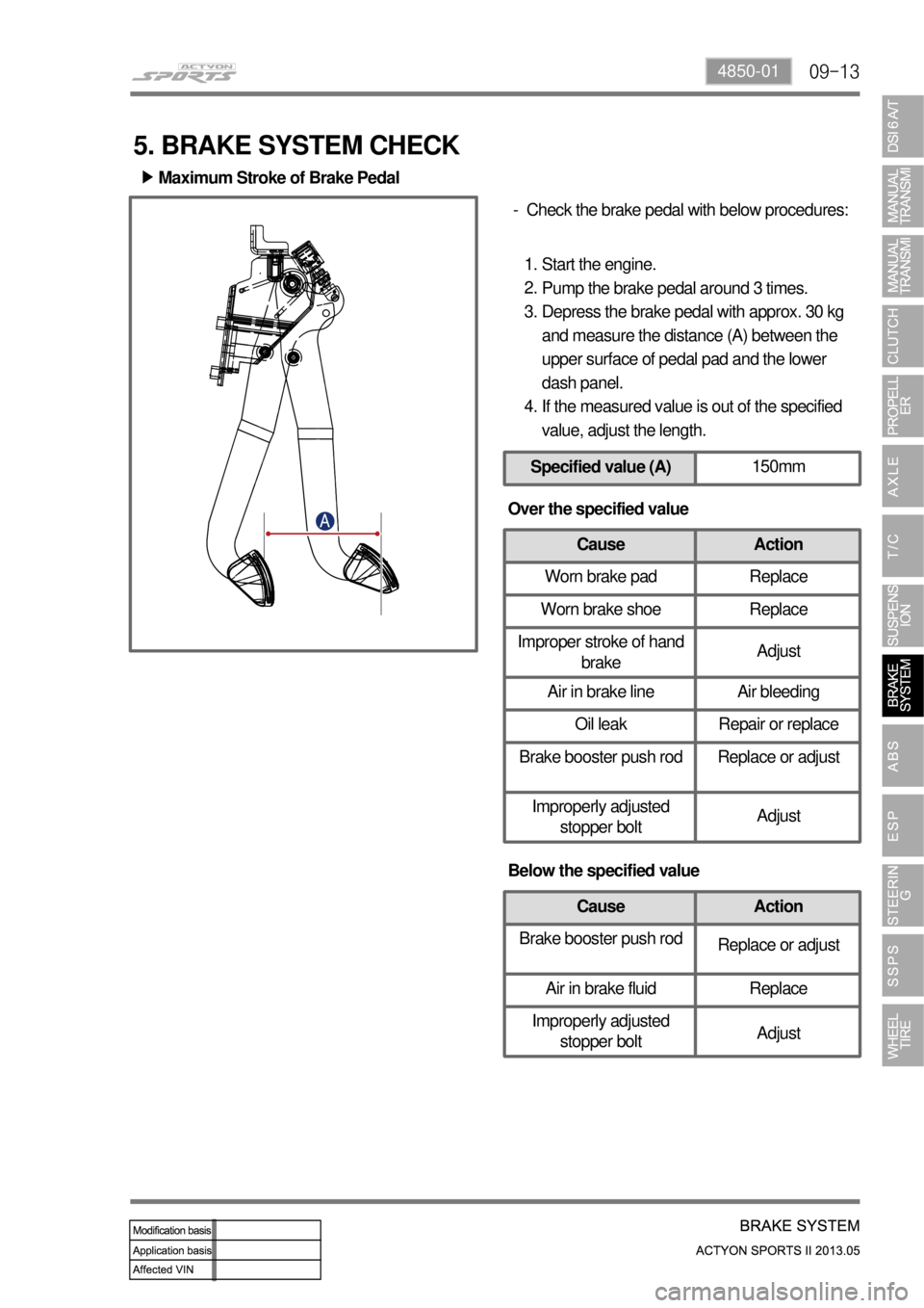
Maximum Stroke of Brake Pedal ▶
Check the brake pedal with below procedures: -
Start the engine.
Pump the brake pedal around 3 times.
Depress the brake pedal with approx. 30 kg
and measure the distance (A) between the
upper surface of pedal pad and the lower
dash panel.
If the measured value is out of the specified
value, adjust the length. 1.
2.
3.
4.
Specified value (A)150mm
5. BRAKE SYSTEM CHECK
Over the specified value
Cause Action
Worn brake pad Replace
Worn brake shoe Replace
Improper stroke of hand
brakeAdjust
Air in brake line Air bleeding
Oil leak Repair or replace
Brake booster push rod Replace or adjust
Improperly adjusted
stopper boltAdjust
Below the specified value
Cause Action
Brake booster push rod
Replace or adjust
Air in brake fluid Replace
Improperly adjusted
stopper boltAdjust
Page 563 of 751

09-14
Specified value (B)155mm
Push rod
Stop lamp
switch Pedal Height ▶
Check the pedal height with below procedures: -
Start the engine and measure the length (A)
between floor mat and pedal.
If the measured value is out of the specified
value, adjust the length. 1.
2.
Adjust the pedal height with below procedures: -
Disconnect the stop lamp switch connector.
Unscrew the lock nut and remove the stop
lamp switch assembly.
Loosen the lock nut on the pedal push rod.
Turn the pedal push rod to adjust the pedal
height.
Tighten the lock nut.
Install the stop lamp switch assembly.
Connect the stop lamp switch connector.
Check if the stop lamps come on when
pressing the brake pedal around 5 mm.
If the stop lamp dpes not come on, adjust the
stop lamp switch assembly again.
If the stop lamps come on, tighten the lock nut
and measure the pedal height again. 1.
2.
3.
4.
5.
6.
7.
8.
9.
10.
Page 564 of 751

09-154850-01
Specified value (A)3 ~ 10mm
Connect the multimeter to stop lamp switch
connector and check if the continuity exists
when pushing in the plunger. If the continuity
doesn't exist, the stop lamp switch is normal. - Pedal Free Play ▶
Stop Lamp Switch ▶Check the pedal free play with below
procedures: -
Stop the engine.
Depress the brake pedal several times to
discharge the vacuum pressure of the brake
booster.
Depress the brake pedal until you feel the
resistance, and measure the movement (A). 1.
2.
3.
Below the specified value: Check if the
distance between the outer case of stop lamp
switch and the brake pedal.
Over the specified value: It may be caused by
bigger clearance between the clevis pin and
the brake pedal arm. Replace the
components if necessary. -
-
Page 565 of 751
09-16
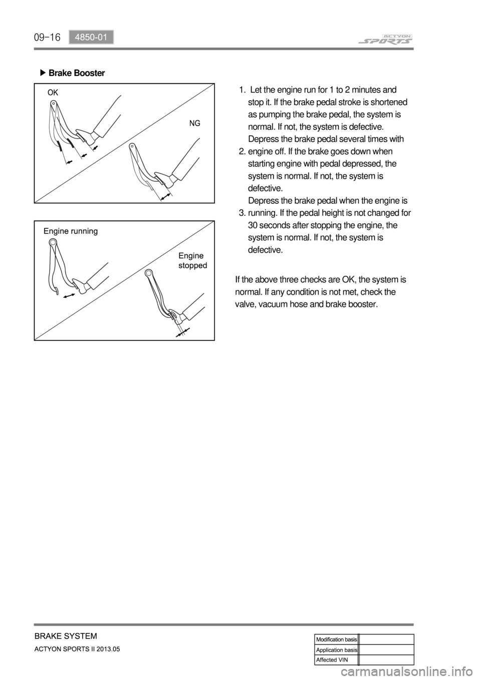
Let the engine run for 1 to 2 minutes and
stop it. If the brake pedal stroke is shortened
as pumping the brake pedal, the system is
normal. If not, the system is defective.
Depress the brake pedal several times with
engine off. If the brake goes down when
starting engine with pedal depressed, the
system is normal. If not, the system is
defective.
Depress the brake pedal when the engine is
running. If the pedal height is not changed for
30 seconds after stopping the engine, the
system is normal. If not, the system is
defective. 1.
2.
3.
If the above three checks are OK, the system is
normal. If any condition is not met, check the
valve, vacuum hose and brake booster. Brake Booster ▶
Page 644 of 751

12-154610-01
Adjusting Plug
Gear Preload Check ▶
Preload is the term used in mechanical engineering to describe the load applied to a fastener merely as
a result of being fastened (and before any external loads are applied)
5. INSPECTION AND MAINTENANCE
Place the wheels at straight ahead direction.
Lift up the vehicle with a lift.
Unscrew the adjusting plug lock nut.
Measure the torque of the adjusting plug. 1.
2.
3.
4.
If the torque is excessive or too low, adjust to
the specified torque. 5.
Place the rack gear to the center position.
Tighten the adjusting plug to 10.2 Nm.
Turn the pinion gear so that the rack gear is
turned to lock to lock 5 times.
Unscrew the adjusting plug.
Tighten the adjusting plug to 4.6 to 5.6 Nm.
Unscrew the adjusting plug to 67.5°. -
-
-
-
-
-
Lock nut
Adjusting Plug
Bushing
Rack support yokeRack support spring
Yoke plugLock nut
Page 645 of 751
12-16
The difference between both sides should be
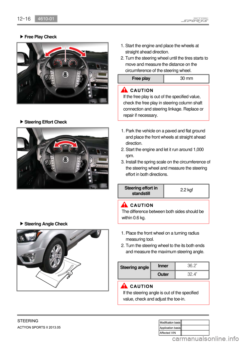
within 0.6 kg.Park the vehicle on a paved and flat ground
and place the front wheels at straight ahead
direction.
Start the engine and let it run around 1,000
rpm.
Install the spring scale on the circumference o
f
the steering wheel and measure the steering
effort in both directions. 1.
2.
3. Steering Effort Check ▶
Steering Angle Check ▶
Place the front wheel on a turning radius
measuring tool.
Turn the steering wheel to the its both ends
and measure the maximum steering angle. 1.
2.
If the steering angle is out of the specified
value, check and adjust the toe-in.
Steering angleInner36.2˚
Outer32.4˚
Free Play Check ▶
Start the engine and place the wheels at
straight ahead direction.
Turn the steering wheel until the tires starts to
move and measure the distance on the
circumference of the steering wheel. 1.
2.
If the free play is out of the specified value,
check the free play in steering column shaft
connection and steering linkage. Replace or
repair if necessary.
Free play30 mm
Steering effort in
standstill2.2 kgf
Page 646 of 751
12-174610-01
Oil Change ▶
Open the power fluid reservoir cap and drain
the fluid completely with oil suction device. To
make it easy, turn the steering wheel to its
both ends several times.
Fill up the specified fluid into fluid reservoir
and bleed air from the steering system. 1.
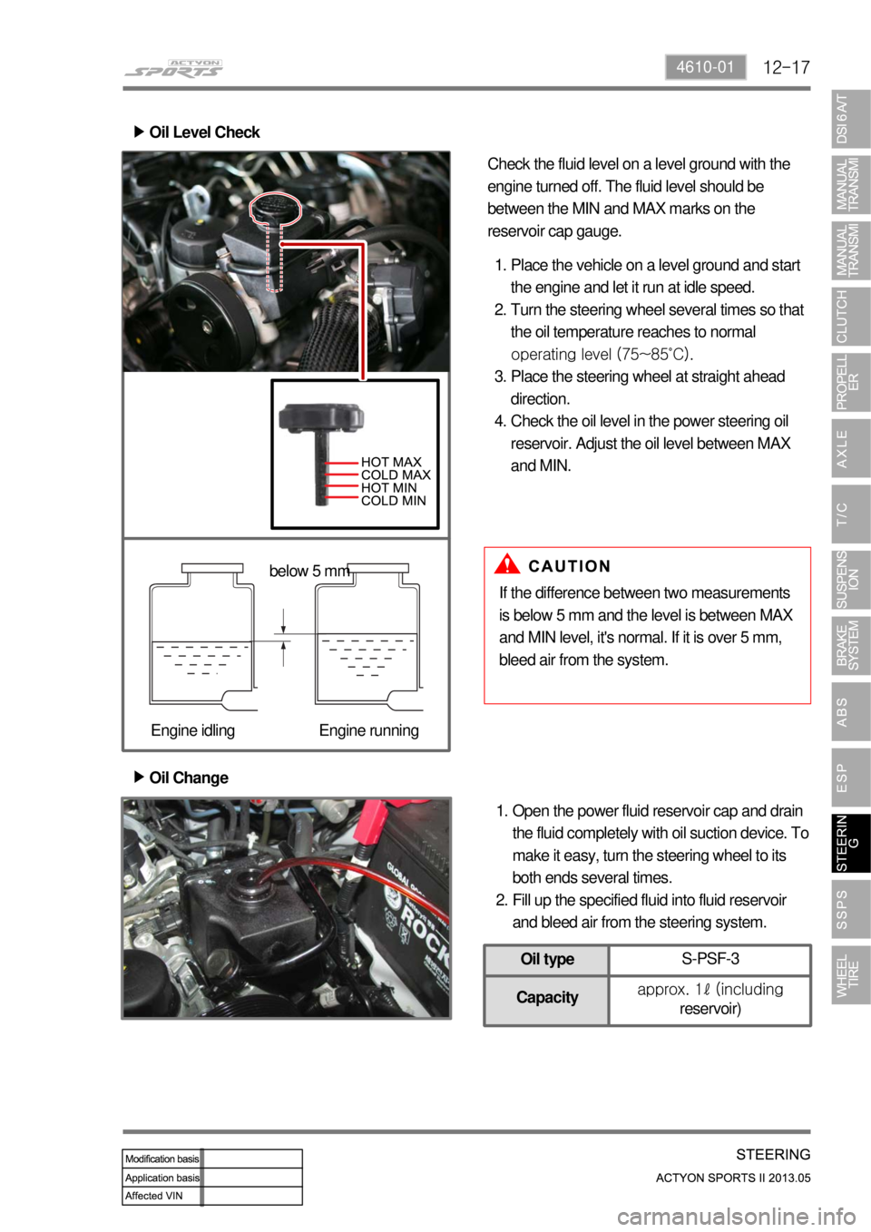
2. Oil Level Check ▶
Place the vehicle on a level ground and start
the engine and let it run at idle speed.
Turn the steering wheel several times so that
the oil temperature reaches to normal
operating level (75~85˚C).
Place the steering wheel at straight ahead
direction.
Check the oil level in the power steering oil
reservoir. Adjust the oil level between MAX
and MIN. 1.
2.
3.
4.
If the difference between two measurements
is below 5 mm and the level is between MAX
and MIN level, it's normal. If it is over 5 mm,
bleed air from the system. Check the fluid level on a level ground with the
engine turned off. The fluid level should be
between the MIN and MAX marks on the
reservoir cap gauge.
below 5 mm
Engine idling Engine running
Oil typeS-PSF-3
Capacityapprox. 1ℓ (including
reservoir)
Page 647 of 751

12-18
Air Bleeding ▶
Lift up the vehicle very carefully.
Turn the steering wheel to its both ends
several times and add the oil up to MAX line
in the steering oil reservoir.
Periodically crank the starting motor and turn
the steering wheel to its both ends without
any interruption.
Check the oil level again. If the oil level is
fluctuated, repeat the procedures from step 3
to step 5.
Start the engine.
Turn the steering wheel to its both ends until
any bubble can be found in the steering oil
reservoir.
Perform the test drive and check the steering
wheel for normal operation and noise.
If the oil level abruptly goes up, bleed the air
from the system again. 1.
2.
3.
4.
5.
6.
7.
8.
The air bleeding should be done after servicing
the power steering system and when the
difference between two measurements (cooled
and normal temperature) is prominent.
Max
Min
Normal Abnormal
If the air bleeding is not properly performed,
the life span of the power steering pump
may be shortened. -
Page 648 of 751
12-194610-01
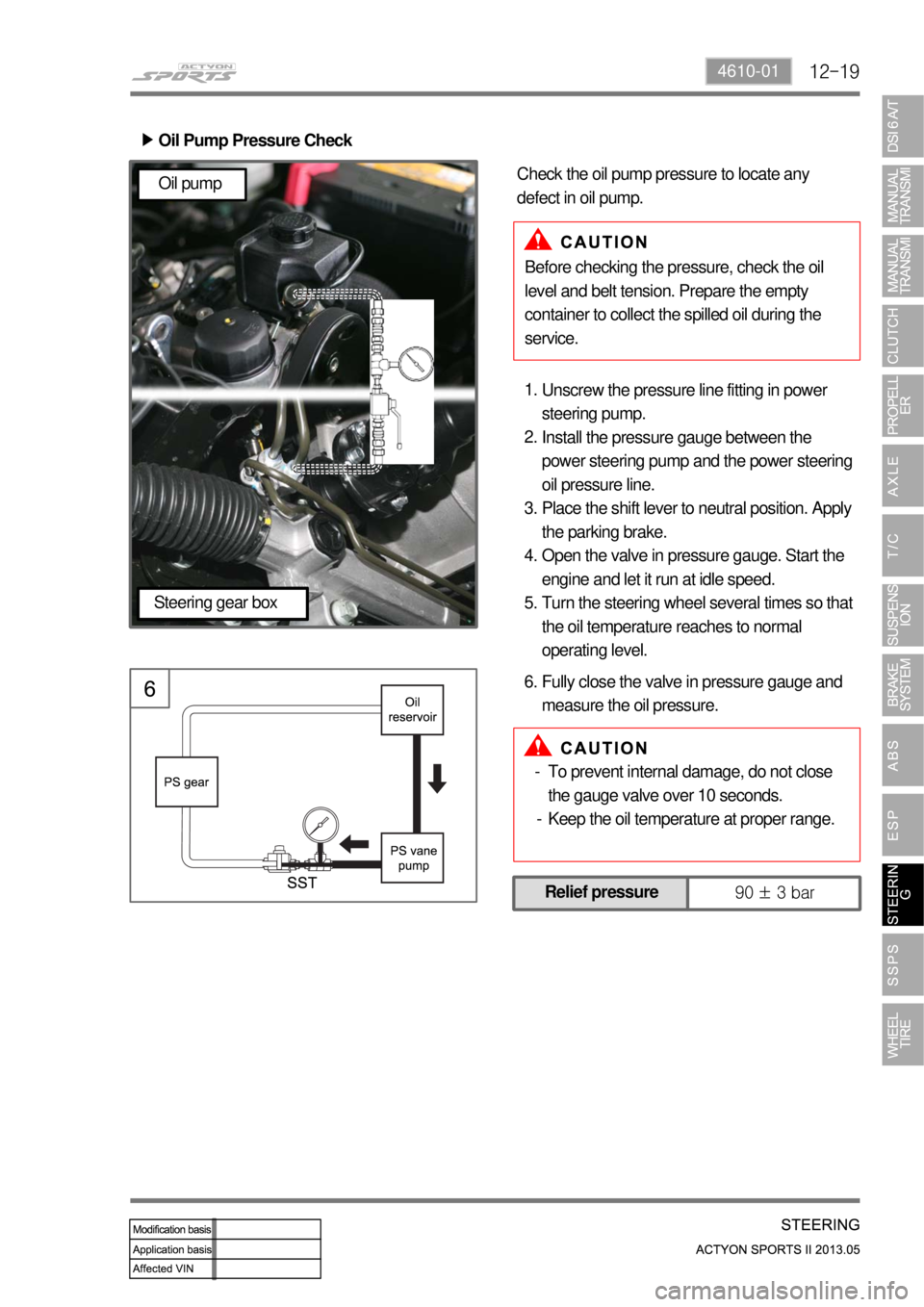
Oil Pump Pressure Check ▶
Unscrew the pressure line fitting in power
steering pump.
Install the pressure gauge between the
power steering pump and the power steering
oil pressure line.
Place the shift lever to neutral position. Apply
the parking brake.
Open the valve in pressure gauge. Start the
engine and let it run at idle speed.
Turn the steering wheel several times so that
the oil temperature reaches to normal
operating level. 1.
2.
3.
4.
5.
Before checking the pressure, check the oil
level and belt tension. Prepare the empty
container to collect the spilled oil during the
service. Check the oil pump pressure to locate any
defect in oil pump.
Fully close the valve in pressure gauge and
measure the oil pressure. 6.
Relief pressure
90 ± 3 bar
Oil pump
Steering gear box
To prevent internal damage, do not close
the gauge valve over 10 seconds.
Keep the oil temperature at proper range. -
-
Page 730 of 751
03-6
3. WARNINGS FOR POWER SEAT
Adjust the driver's seat before driving.
Make sure that the seat is firmly secured after adjusting.
Never drive the vehicle with the head restraint removed or lowered excessively. Otherwise, your neck,
spine or other parts of the body can be severely injured in the event of an accident.
If you recline the seatback excessively, you could slide under the seat belt and be injured severely in a
collision.
Do not put any object that could damage the seat on the seat.
The front and rear seats are equipped with the heated wire (seat warmer) system. Using the seat
warmer system excessively may cause minor burns. The following occupants should exercise special
care when using the heated wire seat. 1.
2.
3.
4.
5.
6.
Infant, child, old or handicapped person
Person with sensitive skin
Exhausted person
Persons who is drunk or took medicine which causes drowsiness such as sleeping pills, cold
tablets, etc. -
-
-
-
Do not place anything on the seat that insulates against the heat, such as a blanket or cushion.
Make sure that the head restraints are in place and secured properly. Never drive the vehicle with the
head restraint removed.
To minimize the injuries in a collision or an abrupt stop, make sure the seatback is in the upright
position before driving. If the seatback is reclined too much, the occupant could slide under the seat
belt in a collision or an abrupt stop and cannot be protected properly by the airbag system. 7.
5.
9.
4. CAUTIONS FOR POWER SEAT
You can operate the power seat with the ignition switch OFF. However, frequent operation of the seat
switch with the engine stopped can result in battery becoming discharged.
Operating more than one seat adjustment switch at the same time can cause damage to the seat
motor. Therefore, operate the seat switch only one at a time.
Do not use organic solvents such as benzene, thinner, alcohol or gasoline to prevent the seat cover
from being damaged while cleaning.
Do not operate the seat position adjustment switch forcefully when the seat does not move or it
contacts an object.
If the power seat is not operated, check and correct the problem before driving off. 1.
2.
3.
4.
5.