lamp SSANGYONG NEW ACTYON SPORTS 2013 Repair Manual
[x] Cancel search | Manufacturer: SSANGYONG, Model Year: 2013, Model line: NEW ACTYON SPORTS, Model: SSANGYONG NEW ACTYON SPORTS 2013Pages: 751, PDF Size: 72.63 MB
Page 415 of 751
06-8
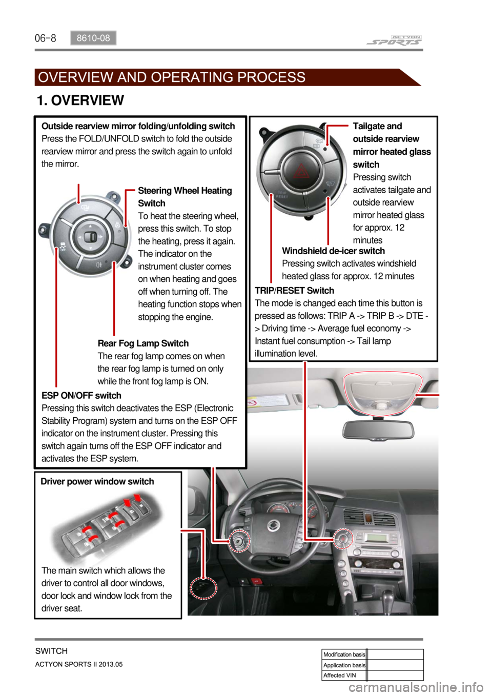
1. OVERVIEW
TRIP/RESET Switch
The mode is changed each time this button is
pressed as follows: TRIP A -> TRIP B -> DTE -
> Driving time -> Average fuel economy ->
Instant fuel consumption -> Tail lamp
illumination level.Windshield de-icer switch
Pressing switch activates windshield
heated glass for approx. 12 minutes
The main switch which allows the
driver to control all door windows,
door lock and window lock from the
driver seat. Tailgate and
outside rearview
mirror heated glass
switch
Pressing switch
activates tailgate and
outside rearview
mirror heated glass
for approx. 12
minutes
Driver power window switchESP ON/OFF switch
Pressing this switch deactivates the ESP (Electronic
Stability Program) system and turns on the ESP OFF
indicator on the instrument cluster. Pressing this
switch again turns off the ESP OFF indicator and
activates the ESP system. Outside rearview mirror folding/unfolding switch
Press the FOLD/UNFOLD switch to fold the outside
rearview mirror and press the switch again to unfold
the mirror.
Rear Fog Lamp Switch
The rear fog lamp comes on when
the rear fog lamp is turned on only
while the front fog lamp is ON.
Steering Wheel Heating
Switch
To heat the steering wheel,
press this switch. To stop
the heating, press it again.
The indicator on the
instrument cluster comes
on when heating and goes
off when turning off. The
heating function stops when
stopping the engine.
Page 416 of 751
06-98610-08
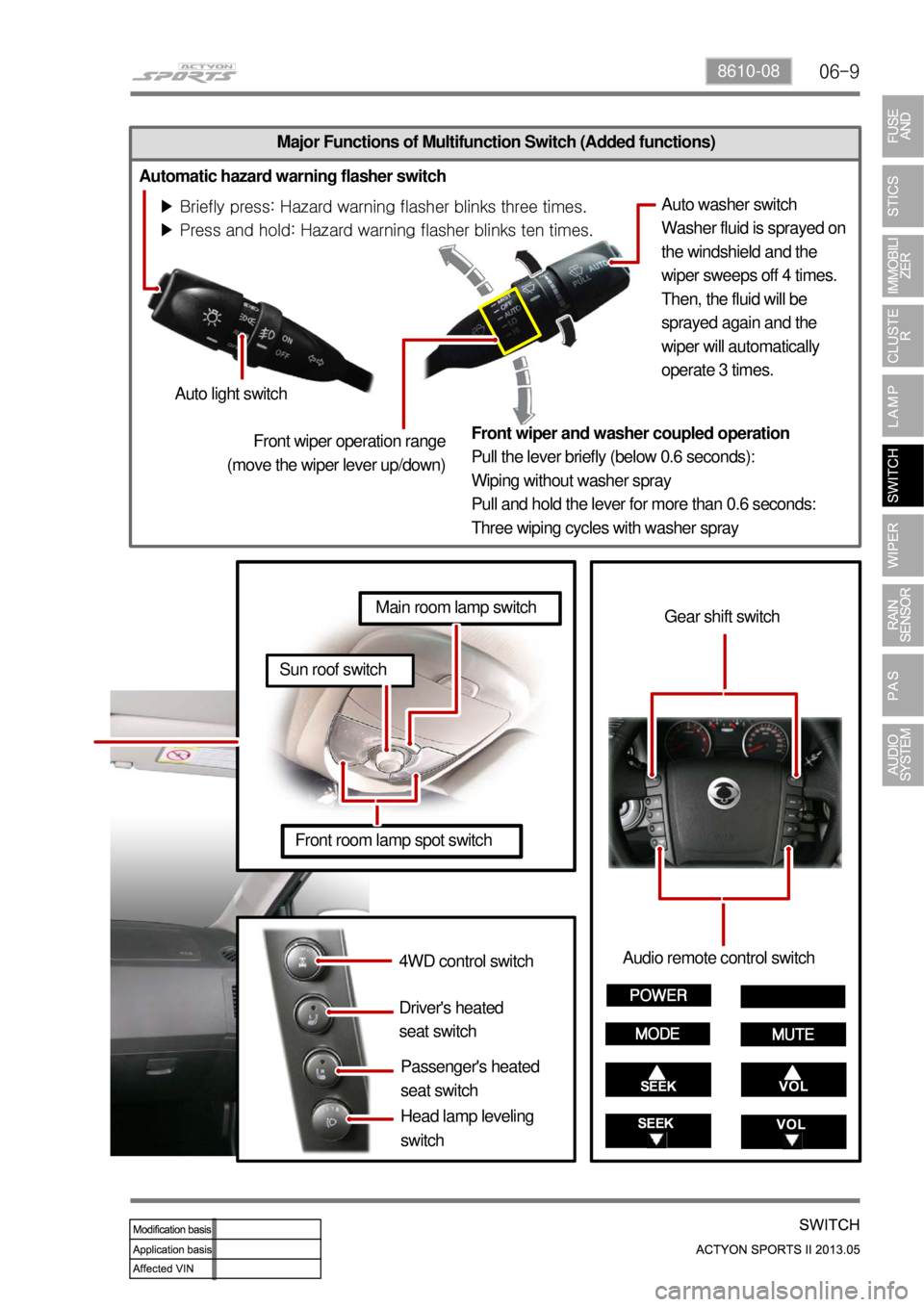
Major Functions of Multifunction Switch (Added functions)
Automatic hazard warning flasher switch
<00470047004700470d960047006900990090008c008d009300a0004700970099008c009a009a00610047006f008800a100880099008b0047009e00880099009500900095008e0047008d00930088009a008f008c0099004700890093009000950092009a00
47009b008f0099008c008c0047009b00900094008c009a0055>
<00470047004700470d96004700770099008c009a009a004700880095008b0047008f00960093008b00610047006f008800a100880099008b0047009e00880099009500900095008e0047008d00930088009a008f008c009900470089009300900095009200
9a0047009b008c00950047009b00900094008c009a0055>Auto washer switch
Washer fluid is sprayed on
the windshield and the
wiper sweeps off 4 times.
Then, the fluid will be
sprayed again and the
wiper will automatically
operate 3 times.
Auto light switch
Front wiper and washer coupled operation
Pull the lever briefly (below 0.6 seconds):
Wiping without washer spray
Pull and hold the lever for more than 0.6 seconds:
Three wiping cycles with washer spray
4WD control switch
Driver's heated
seat switch
Passenger's heated
seat switchAudio remote control switch
Gear shift switch
Front room lamp spot switch
Sun roof switch
Main room lamp switch
Front wiper operation range
(move the wiper lever up/down)
Head lamp leveling
switch
Page 428 of 751
08-4
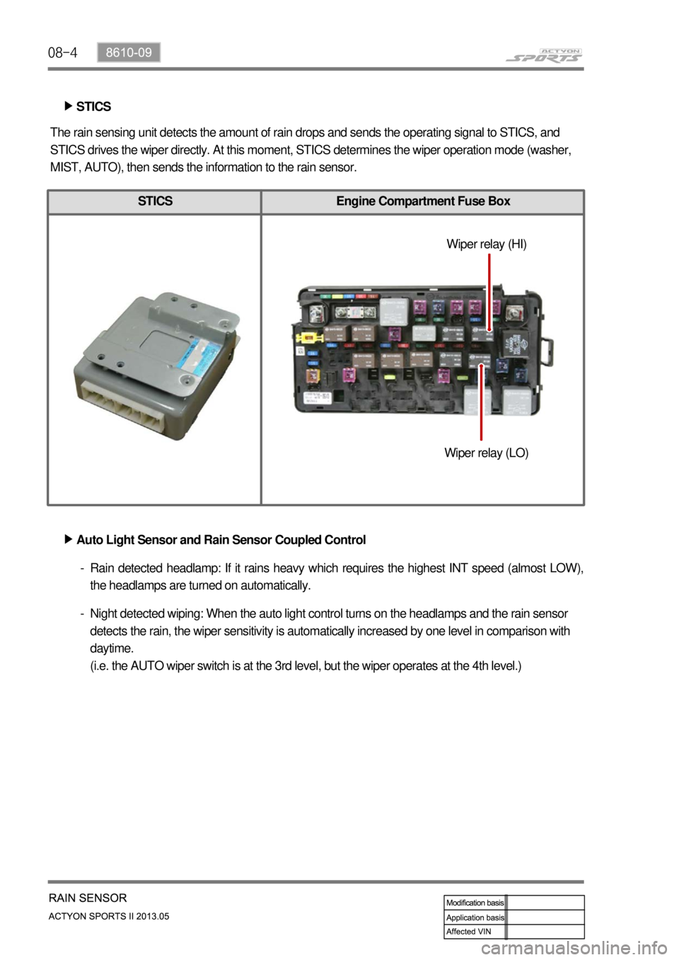
STICS Engine Compartment Fuse Box
STICS ▶
The rain sensing unit detects the amount of rain drops and sends the operating signal to STICS, and
STICS drives the wiper directly. At this moment, STICS determines the wiper operation mode (washer,
MIST, AUTO), then sends the information to the rain sensor.
Auto Light Sensor and Rain Sensor Coupled Control ▶
Rain detected headlamp: If it rains heavy which requires the highest INT speed (almost LOW),
the headlamps are turned on automatically. -
Night detected wiping: When the auto light control turns on the headlamps and the rain sensor
detects the rain, the wiper sensitivity is automatically increased by one level in comparison with
daytime.
(i.e. the AUTO wiper switch is at the 3rd level, but the wiper operates at the 4th level.) -Wiper relay (HI)
Wiper relay (LO)
Page 431 of 751

08-78610-09
3) Sensitivity Control
The wiper LOW relay is turned on and the wiper motor runs one cycle when the volume
<009a008c0095009a0090009b0090009d0090009b00a000470090009a004700900095008a0099008c0088009a008c008b0047004f008c009f00610047009a008c0095009a0090009b0090009d0090009b00a00047005700470d7d0047005800500047009e00
8f00900093008c0047009b008f008c00470090008e00950090>tion switch and the INT switch is
in the "ON" position, and the wiper motor is in "Parked" position). However, the wiper motor can
be operated only when the rain sensor detects the "Rain Detected" signal. 1.
If the volume sensitivity is changed more than 1 stage within 2 seconds, the wiper motor runs only
one cycle.
4) Auto Light Control
Only when the auto light switch is in "AUTO" position, it controls the tail lamp and headlamp by
communicating with the rain sensor (while the ignition key is in "ON" position). 1.
Page 436 of 751

08-12
Rain detected headlamp: If it rains heavy which requires the highest INT speed (almost LOW), the
headlamps are turned on automatically.
Night detected wiping: When the auto light control turns on the headlamps and the rain sensor
detects the rain, the wiper sensitivity is automatically increased by one level in comparison with
daytime.
(i.e. the AUTO wiper switch is at the 3rd level, but the wiper operates at the 4th level.) 1.
2.
3. OPERATION MODE OF RAIN SENSING WIPER SYSTEM
Page 462 of 751
01-16
4. LIMP HOME MODE
In case of transmission malfunction ▶
If a serious fault occurs in the automatic transmission, the TCU enters the limp home mode to
secure safe driving and protect the automatic transmission.
As power is no longer supplied to the solenoid, the current basic function (P, R, N, D) is
maintained and the 4th gear can be maintained only by the operation of the hydraulic system
without electrical operation.
The ECU communicates with other electric modules with CAN. If a serious fault occurs, the
transmission automatically enters the limp home mode for service.
The TCU monitors all factors which can affect to the performance of the transmission and
diagnose the system according to OBD II regulation. 1.
2.
3.
4.
In case of overheated transmission ▶
The TCU enters the limp home mode when the batter voltage drops below 8 V.
If the transmission is overheated, the shift pattern is changed to the hot mode to cool the
transmission more efficiently.
While the transmission is overheated, the selector lever symbol and engine temperature warning
lamp on the instrument cluster blink until the transmission is cooled down to the normal operation
temperature. If the transmission is excessively overheated, the gear cannot be shifted but
remains in the neutral position. 1.
2.
3.
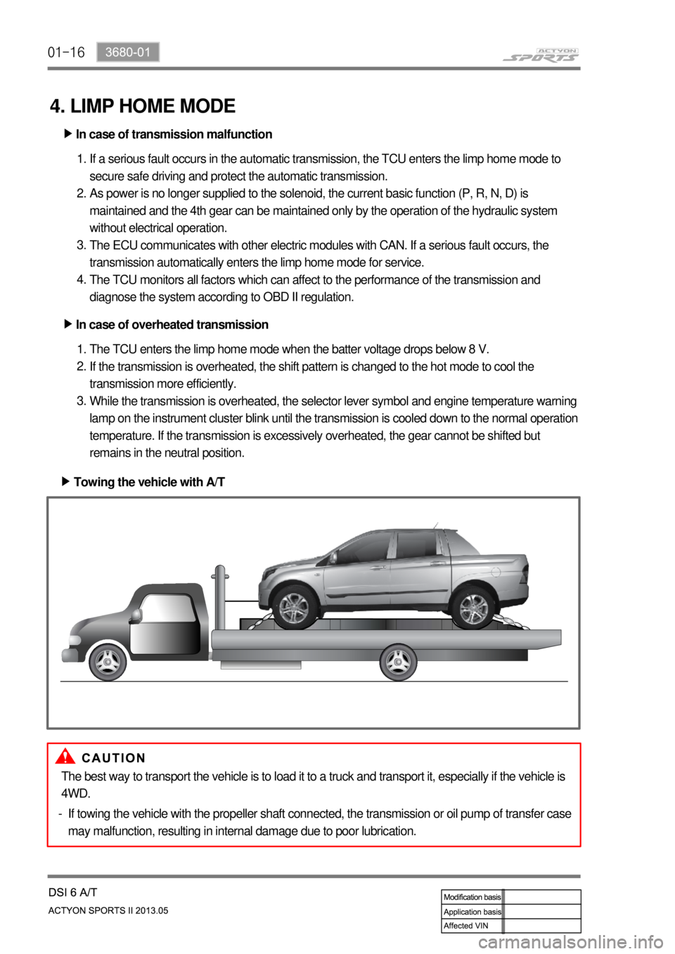
Towing the vehicle with A/T ▶
The best way to transport the vehicle is to load it to a truck and transport it, especially if the vehicle is
4WD.
If towing the vehicle with the propeller shaft connected, the transmission or oil pump of transfer case
may malfunction, resulting in internal damage due to poor lubrication. -
Page 463 of 751
01-173680-01
5. ELECTRONIC CONTROL SYSTEM
1) Overview
The transmission control unit (TCU) and its input/output networks control the operations of transmission:
Shift timing
Line pressure
Clutch pressure (shift feel)
Torque converter clutch -
-
-
-
In addition, the TCU receives input signals from certain transmission-related sensors and switches. The
TCU also uses these signals when determining transmission operating strategy. Using all of these input
signals, the TCU can determine when the time and conditions are right for a shift, or when to apply or
release the torque converter clutch. It will also determine the pressure needed to optimise shift feel. To
accomplish this, the TCU operates six variable bleed control solenoids and four ON/OFF solenoids to
control the operations of transmission.
2) Transmission Control Unit (TCU)
The transmission control unit (TCU) is mounted under the driver's seat and controls the operation of the
transmission.
TCU processes the analog information from the internal sensors and the digital information through CAN
communication lines. TCU monitors all the input and output signals. If there is any failure, TCU changes
the system to “Limp Home Mode” and alerts to the driver through the warning lamp on the
instrument cluster.
(1) Hard-wired (Analog) Input/Output
Input/Output Data between TGS Lever and TCU ▶
Position and conditions of gear select lever
Driving moded (Winter or Standard) -
-
Position of inhibitor switch - Input/Output Data between Inhibitor and TCU ▶
6 control signals for variable bleed solenoid
4 control signals for ON/OFF solenoid
Transmission input speed
Transmission output speed
Transmission oil temperature
EMM (Embeded Memory Module) -
-
-
-
-
- Input/Output Data between Automatic Transmission and TCU ▶
Input/Output Data between Self Diagnostic Connector and TCU ▶
Various DTC codes and TCU information -
Page 504 of 751

02-6
3. TIGHTENING TORQUE
Part nameTightening torque
(Nm)Numbers Adhesive
1. Seal bolt (rolling plunger and guide spring) 53.9~67.6 1EA Loctite
2. Guide bolt 14.7~21.5 1EA Loctite
3. Pocket ball bearing bolt 29.4~41.1 1EA Loctite
4. Reverse shift fork retainer bolt 53.9~67.6 2EA Loctite
5. Backup lamp switch 29.4~34.3 1EA Loctite
6. Oil drain plug 58.8~78.4 1EA Loctite
7. Interlock bolt 14.7~21.5 1EA -
8. Neutral switch 29.4~34.3 1EA Loctite
9. Oil filler plug 58.8~78.4 1EA Loctite
10. Extension housing bolt 42.1~53.9 12EA -
11. Concentric slave cylinder bolt 9.8~15.6 3EA -
12. Front bearing retainer bolt 19.6~24.5 8EA Loctite
Page 511 of 751

02-133170-01
3166-00 Extension housing ▶
Lever assembly - Semi remote
Lever - Shift
Boot - Rubber
Ring - Retainer
O-ring
Bearing
Shim
Arm - Control
Damper assembly
Rod assembly
Bushing assembly - TGS mounting
Pin - TGS mounting
Pin - Spring
Pin - Spring
Adapter - Case 1.
3.
4.
5.
6.
7.
8.
9.
10.
13.
14.
15.
16.
17.
20.Bolt - Flange (42.1 ~ 53.9 Nm)
Seal - Oil
Seal - Oil
Pin - Dowel
Switch - Neutral (29.4 ~ 34.3 Nm)
Gasket
Bolt - Interlock (14.7 ~ 21.5 Nm)
Pin - Detent
Switch - Backup lamp (29.4 ~ 34.3 Nm)
Bolt - Fork hinge (53.9 ~ 67.6 Nm)
Bearing - Poppet ball (29.4 ~ 41.1 Nm)
Bolt - Guide (14.7 ~ 21.5 Nm)
Bolt (2.9 ~ 4.9 Nm)
Bracket - Wiring 21.
22.
23.
24.
25.
26.
27.
28.
29.
30.
31.
32.
33.
34.
Page 518 of 751

02-20
3. SHIFTING MECHANISM
High-Force mechanism for
reverse gear shift
3rd/4th 1st/2ndR
5th/6th
Neutral switch
Backup lamp switch
Control shaft
Control finger
Lug arrangement