ignition SSANGYONG NEW ACTYON SPORTS 2013 Manual Online
[x] Cancel search | Manufacturer: SSANGYONG, Model Year: 2013, Model line: NEW ACTYON SPORTS, Model: SSANGYONG NEW ACTYON SPORTS 2013Pages: 751, PDF Size: 72.63 MB
Page 592 of 751
10-12
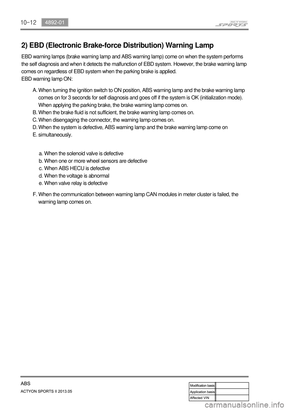
2) EBD (Electronic Brake-force Distribution) Warning Lamp
EBD warning lamps (brake warning lamp and ABS warning lamp) come on when the system performs
the self diagnosis and when it detects the malfunction of EBD system. However, the brake warning lamp
comes on regardless of EBD system when the parking brake is applied.
EBD warning lamp ON:
When turning the ignition switch to ON position, ABS warning lamp and the brake warning lamp
comes on for 3 seconds for self diagnosis and goes off if the system is OK (initialization mode).
When applying the parking brake, the brake warning lamp comes on.
When the brake fluid is not sufficient, the brake warning lamp comes on.
When disengaging the connector, the warning lamp comes on.
When the system is defective, ABS warning lamp and the brake warning lamp come on
simultaneously. A.
B.
C.
D.
E.
When the solenoid valve is defective
When one or more wheel sensors are defective
When ABS HECU is defective
When the voltage is abnormal
When valve relay is defective a.
b.
c.
d.
e.
When the communication between warning lamp CAN modules in meter cluster is failed, the
warning lamp comes on. F.
Page 615 of 751

11-134890-10
5. WARNING LAMPS
1) ABS Warning Lamp
ABS warning lamp module indicates the self diagnosis and malfunction.
ABS warning lamp ON:
When turning the ignition switch to ON position, ABS warning lamp comes on for 3 seconds for
self diagnosis and goes off if the system is OK (initialization mode).
When the system is defective, the warning lamp comes on.
When disengaging the connector, the warning lamp comes on.
ABS is not available during lamp ON. In this condition, Only normal brake system without ABS
function is available.
When the communication between warning lamp CAN module in meter cluster, the warning
lamp comes on. 1.
2.
3.
4.
5.ABS warning lamp
Brake warning lamp
ESP OFF indicator
ESP warning lamp/indicator
EBD warning lamp 1.
2.
3.
4.
5.
Page 616 of 751
11-14
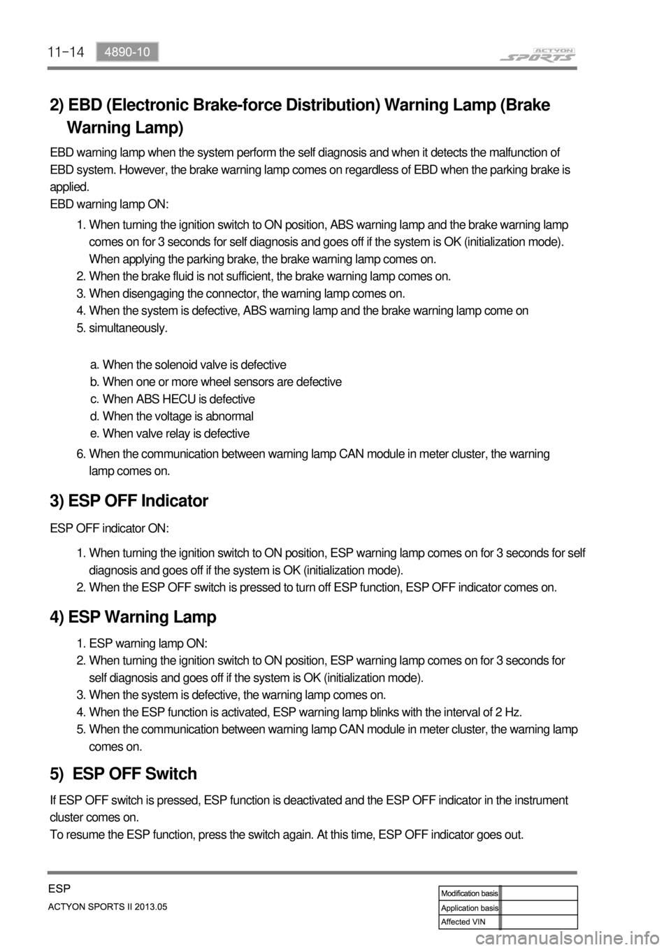
2) EBD (Electronic Brake-force Distribution) Warning Lamp (Brake
Warning Lamp)
EBD warning lamp when the system perform the self diagnosis and when it detects the malfunction of
EBD system. However, the brake warning lamp comes on regardless of EBD when the parking brake is
applied.
EBD warning lamp ON:
When turning the ignition switch to ON position, ABS warning lamp and the brake warning lamp
comes on for 3 seconds for self diagnosis and goes off if the system is OK (initialization mode).
When applying the parking brake, the brake warning lamp comes on.
When the brake fluid is not sufficient, the brake warning lamp comes on.
When disengaging the connector, the warning lamp comes on.
When the system is defective, ABS warning lamp and the brake warning lamp come on
simultaneously. 1.
2.
3.
4.
5.
When the solenoid valve is defective
When one or more wheel sensors are defective
When ABS HECU is defective
When the voltage is abnormal
When valve relay is defective a.
b.
c.
d.
e.
When the communication between warning lamp CAN module in meter cluster, the warning
lamp comes on. 6.
3) ESP OFF Indicator
ESP OFF indicator ON:
When turning the ignition switch to ON position, ESP warning lamp comes on for 3 seconds for self
diagnosis and goes off if the system is OK (initialization mode).
When the ESP OFF switch is pressed to turn off ESP function, ESP OFF indicator comes on. 1.
2.
4) ESP Warning Lamp
ESP warning lamp ON:
When turning the ignition switch to ON position, ESP warning lamp comes on for 3 seconds for
self diagnosis and goes off if the system is OK (initialization mode).
When the system is defective, the warning lamp comes on.
When the ESP function is activated, ESP warning lamp blinks with the interval of 2 Hz.
When the communication between warning lamp CAN module in meter cluster, the warning lamp
comes on. 1.
2.
3.
4.
5.
5) ESP OFF Switch
If ESP OFF switch is pressed, ESP function is deactivated and the ESP OFF indicator in the instrument
cluster comes on.
To resume the ESP function, press the switch again. At this time, ESP OFF indicator goes out.
Page 688 of 751
01-96810-01
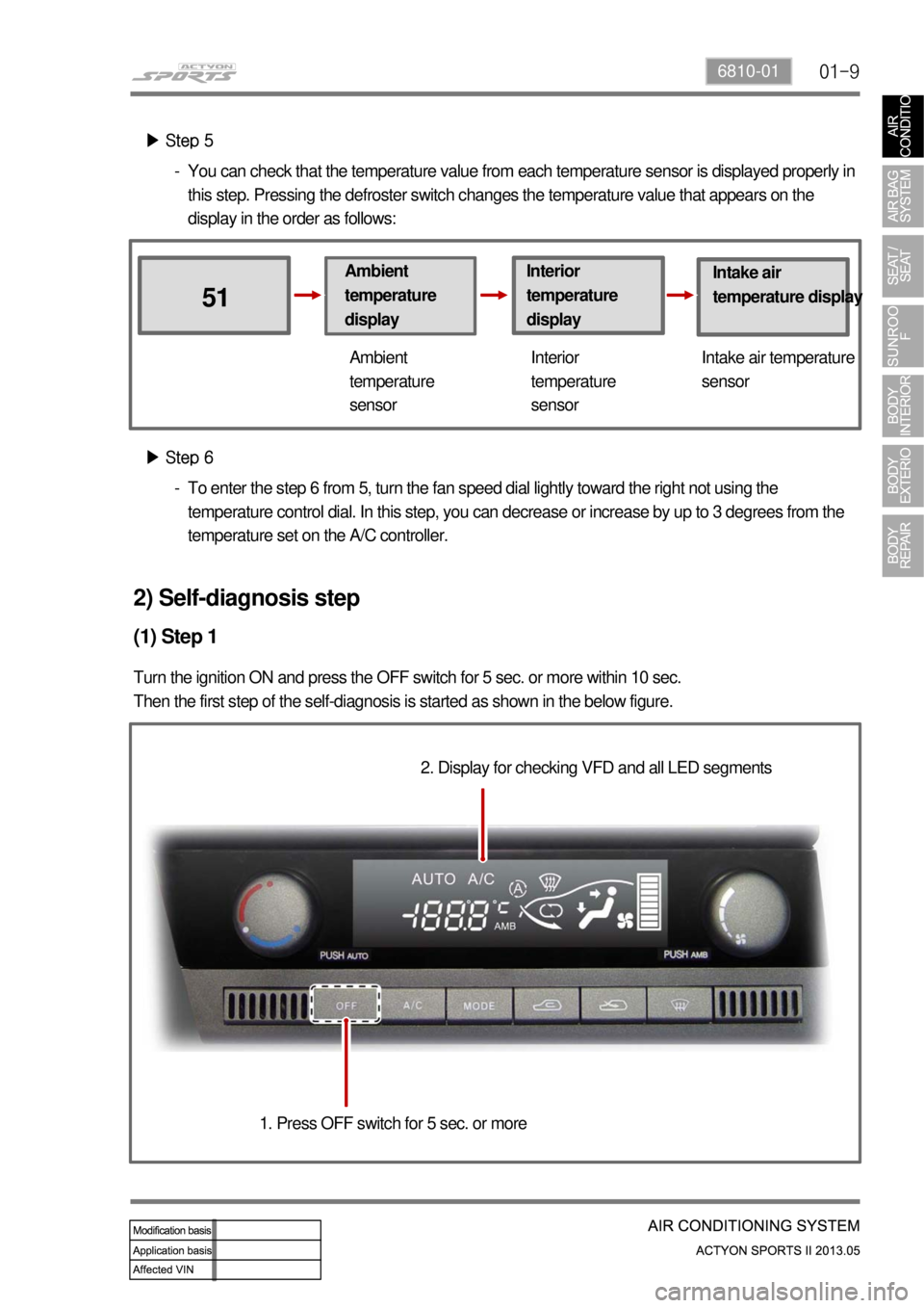
▶ Step 5
Ambient
temperature
display
51
Interior
temperature
displayIntake air
temperature display
Ambient
temperature
sensorInterior
temperature
sensorIntake air temperature
sensor
▶ Step 6
To enter the step 6 from 5, turn the fan speed dial lightly toward the right not using the
temperature control dial. In this step, you can decrease or increase by up to 3 degrees from the
temperature set on the A/C controller. -You can check that the temperature value from each temperature sensor is displayed properly in
this step. Pressing the defroster switch changes the temperature value that appears on the
display in the order as follows: -
2) Self-diagnosis step
(1) Step 1
Turn the ignition ON and press the OFF switch for 5 sec. or more within 10 sec.
Then the first step of the self-diagnosis is started as shown in the below figure.
2. Display for checking VFD and all LED segments
1. Press OFF switch for 5 sec. or more
Page 693 of 751

01-14
(7) How to end self-diagnosis
Turn the AUTO switch ON or turn OFF the ignition key.
(8) When A/C system is faulty (Initial auto-diagnosis)
The fault code for the faulty sensor is not displayed. Therefore you should start the self-diagnosis to
check the system.
Page 694 of 751

01-156810-01
3) Trouble Diagnosis
(1) Duct Temperature Sensor
If the fault code for the duct temperature sensor (DTC 3) appears on the display, check the sensor as
follows:
Remove the duct temperature sensor and measure the resistance between the terminals of the
<008a009600950095008c008a009b009600990047004f009a0097008c008a0090008d0090008a0088009b0090009600950061004700880097009700990096009f0055004700590055005900470092007e00470088009b00470059005c0b4500500055004700
70008d0047009b008f008c00470099008c009a0090009a009b>ance value is extremely high or
low, replace the duct temperature sensor.
If the result is not as specified, replace the duct temperature sensor. If the result is as specified,
proceed to the next step.
Turn the ignition switch to ON position and measure the voltage between the connector of the FATC
<008a00960095009b0099009600930093008c0099004700880095008b0047009b008f008c0047008b009c008a009b0047009b008c00940097008c00990088009b009c0099008c0047009a008c0095009a009600990047004f009a0097008c008a0090008d00
90008a0088009b009000960095006100470088009700970099>ox. 2 V at 25℃).
If the voltage cannot be measured, check the wiring for open circuit. If the result is as specified,
replace the FATC controller. A.
B.
C.
D.
(2) Power Transistor
If the fault code for the power transistor (DTC 6) is displayed, check as follows:
Turn the ignition switch to ON position.
Measure the voltage between the terminals of the blower motor while changing the fan speed from
the lowest level to the highest level.
The specified voltage value in each stage: A.
B.
C.
If the voltage is out of specified value, check the wiring for open circuit. If the wiring is intact, replace
the power transistor. D.
(3) Thermo AMP Sensor (Intake Air Sensor)
If the A/C is not turned on, check as follows:
Remove the thermo AMP and measure the voltage between the terminals no. 1 and 2 of the
connector.
Check if the voltage is approx. 12 V when the output is ON and 0 V when the output is OFF.
If the voltage value is not as specified, replace the thermo AMP. If the value is as specified, proceed
to the next step.
Turn the ignition switch to ON position and turn on the A/C by pressing the A/C button. And measure
the voltage between the terminals A12 and A11 of the FATC controller connector (specification:
approx. 12 V).
If the voltage cannot be measured, check the wiring for open circuit. If the result is not as specified,
replace the thermo AMP. A.
B.
C.
D.
E.
Page 695 of 751

01-16
(4) Sun-load sensor
Remove the sun-load sensor and measure the current between the terminals with the sensor
exposed to direct sunlight.
Measure the current again in the shade. If this value is lower than the measured value in the
sunlight, the sensor is intact.
Turn the ignition switch to the "ON" position.
Measure the voltage between the terminals of the sun sensor at the FATC connector. (approx. 2.5 V
under sunlight and approx. 4.8 V under shade)
If the voltage cannot be measured, check the wiring for open circuit. If the result is not as specified,
replace the FATC controller. A.
B.
C.
D.
E.
Page 723 of 751
02-14
4. DEPLOYMENT
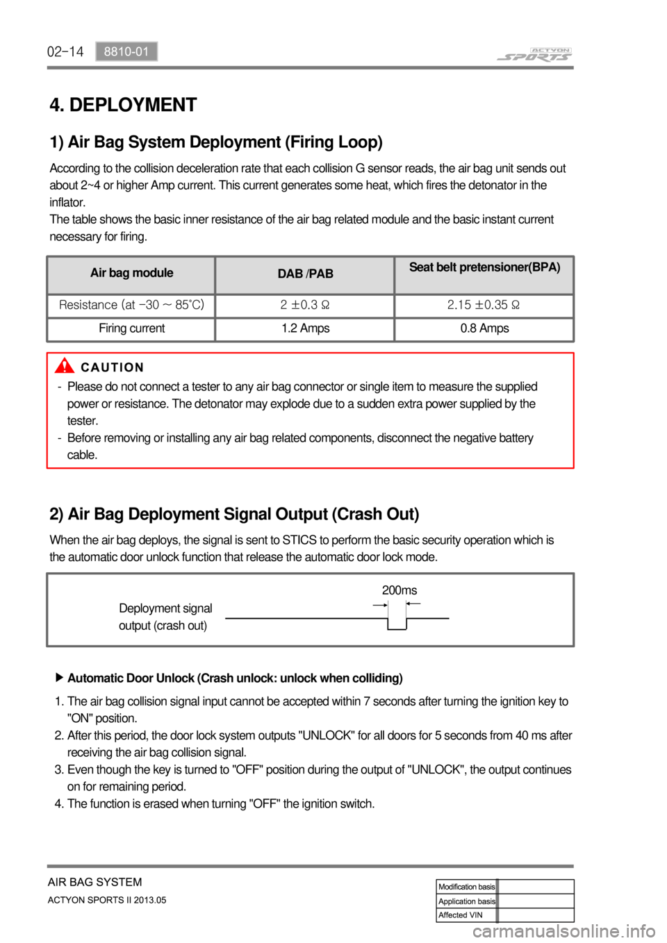
According to the collision deceleration rate that each collision G sensor reads, the air bag unit sends out
about 2~4 or higher Amp current. This current generates some heat, which fires the detonator in the
inflator.
The table shows the basic inner resistance of the air bag related module and the basic instant current
necessary for firing.
1) Air Bag System Deployment (Firing Loop)
2) Air Bag Deployment Signal Output (Crash Out)
When the air bag deploys, the signal is sent to STICS to perform the basic security operation which is
the automatic door unlock function that release the automatic door lock mode.
Deployment signal
output (crash out)200ms
Automatic Door Unlock (Crash unlock: unlock when colliding) ▶
The air bag collision signal input cannot be accepted within 7 seconds after turning the ignition key to
"ON" position.
After this period, the door lock system outputs "UNLOCK" for all doors for 5 seconds from 40 ms after
receiving the air bag collision signal.
Even though the key is turned to "OFF" position during the output of "UNLOCK", the output continues
on for remaining period.
The function is erased when turning "OFF" the ignition switch. 1.
2.
3.
4.
Air bag module
DAB /PABSeat belt pretensioner(BPA)
Resistance (at -30 ~ 85˚C) 2 ±0.3 Ω 2.15 ±0.35 Ω
Firing current 1.2 Amps 0.8 Amps
Please do not connect a tester to any air bag connector or single item to measure the supplied
power or resistance. The detonator may explode due to a sudden extra power supplied by the
tester.
Before removing or installing any air bag related components, disconnect the negative battery
cable. -
-
Page 724 of 751

02-158810-01
The "Unlock" control by air bag signal prevails over any "LOCK" or "UNLOCK" control by other
functions.
The "LOCK/UNLOCK" request by other functions will be ignored after/during the output of
"UNLOCK" by the air bag.
However, the door lock is controlled by other functions when the ignition switch is "OFF".
"LOCK" (or "UNLOCK") output is ignored if "LOCK" (or "UNLOCK") output is required while
performing the output of "LOCK" (or "UNLOCK").
However, UNLOCK by air bag signal and operation by the remote control key are valid.
If the door lock system outputs "LOCK" and "UNLOCK" simultaneously, only the "LOCK" output can
be activated. 1.
2.
3.
4.Cautions for Door Lock/Unlock Control ▶
ING KEY
SW(*1)
Deployment
signal
Door unlock
relayON
OFF
ON
OFF
ON
OFF
T1 : 200ms T2 : 40ms T3 : 5s T3 T2 T1
Page 725 of 751
02-16
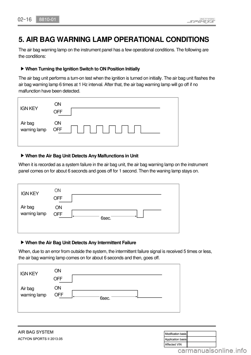
5. AIR BAG WARNING LAMP OPERATIONAL CONDITIONS
The air bag warning lamp on the instrument panel has a few operational conditions. The following are
the conditions:
When Turning the Ignition Switch to ON Position Initially ▶
The air bag unit performs a turn-on test when the ignition is turned on initially. The air bag unit flashes the
air bag warning lamp 6 times at 1 Hz interval. After that, the air bag warning lamp will go off if no
malfunction have been detected.
When the Air Bag Unit Detects Any Malfunctions in Unit ▶
When the Air Bag Unit Detects Any Intermittent Failure ▶ When it is recorded as a system failure in the air bag unit, the air bag warning lamp on the instrument
panel comes on for about 6 seconds and goes off for 1 second. Then the waning lamp stays on.
When, due to an error from outside the system, the intermittent failure signal is received 5 times or less,
the air bag warning lamp comes on for about 6 seconds and then, goes off.
IGN KEY
Air bag
warning lamp
IGN KEY
Air bag
warning lamp IGN KEY
Air bag
warning lamp
ON
OFF
OFF ON
OFF
ON
OFF
ON
OFF
ON
OFF
6sec.
6sec. ON