steering SSANGYONG RODIUS 2005 Service Manual
[x] Cancel search | Manufacturer: SSANGYONG, Model Year: 2005, Model line: RODIUS, Model: SSANGYONG RODIUS 2005Pages: 502, PDF Size: 70.43 MB
Page 212 of 502
0-5
TORQUE ON DEMAND
RODIUS 2005.07
3240-01
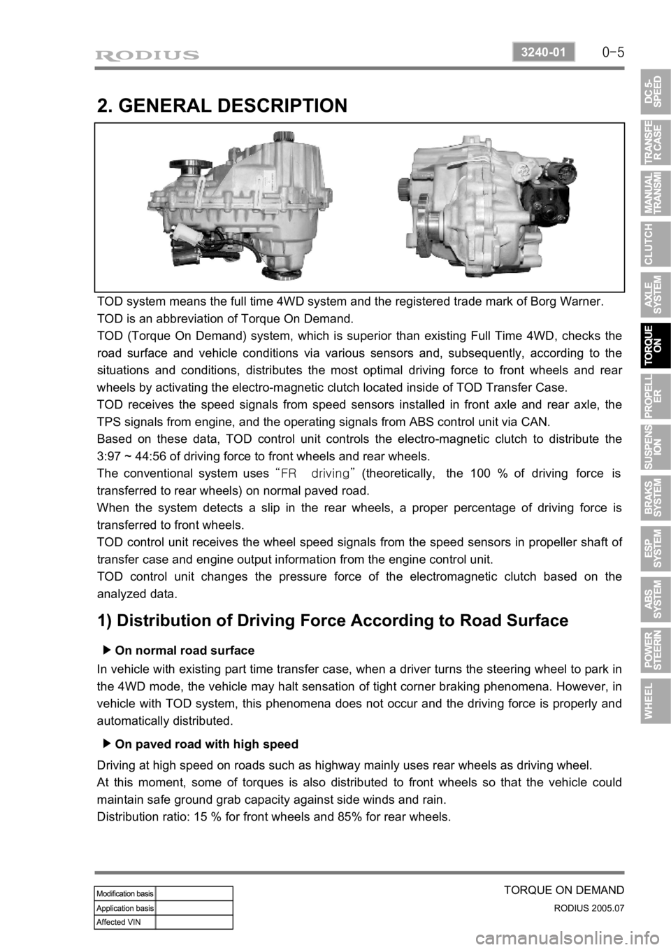
2. GENERAL DESCRIPTION
TOD system means the full time 4WD system and the registered trade mark of Borg Warner.
TOD is an abbreviation of Torque On Demand.
TOD (Torque On Demand) system, which is superior than existing Full Time 4WD, checks the
road surface and vehicle conditions via various sensors and, subsequently, according to the
situations and conditions, distributes the most optimal driving force to front wheels and rea
r
wheels by activating the electro-magnetic clutch located inside of TOD Transfer Case.
TOD receives the speed signals from speed sensors installed in front axle and rear axle, the
TPS signals from engine, and the operating signals from ABS control unit via CAN.
Based on these data, TOD control unit controls the electro-magnetic clutch to distribute the
3:97 ~ 44:56 of driving force to front wheels and rear wheels.
The conventional system uses “FR driving” (theoretically, the 100 % of driving force is
transferred to rear wheels) on normal paved road.
When the system detects a slip in the rear wheels, a proper percentage of driving force is
transferred to front wheels.
TOD control unit receives the wheel speed signals from the speed sensors in propeller shaft o
f
transfer case and engine output information from the engine control unit.
TOD control unit changes the pressure force of the electromagnetic clutch based on the
analyzed data.
1) Distribution of Driving Force According to Road Surface
On normal road surface ▶
In vehicle with existing part time transfer case, when a driver turns the steering wheel to park in
the 4WD mode, the vehicle may halt sensation of tight corner braking phenomena. However, in
vehicle with TOD system, this phenomena does not occur and the driving force is properly and
automatically distributed.
On paved road with high speed ▶
Driving at high speed on roads such as highway mainly uses rear wheels as driving wheel.
At this moment, some of torques is also distributed to front wheels so that the vehicle could
maintain safe ground grab capacity against side winds and rain.
Distribution ratio: 15 % for front wheels and 85% for rear wheels.
Page 213 of 502
0-6
RODIUS 2005.07
3240-01
TORQUE ON DEMAND
When turning on the road with low friction rate ▶
During cornering on roads such as unpaved, snowy, icy and muddy, ground grab capacity is
increased by distributing required torque and, at the same time, comfortable steering operation
is maintained by controlling the ground grab capacity at high level.
Distribution ratio: 30 % for front wheels and 70 % for rear wheels.
When climbing or starting off on the road with low friction rate ▶
In order to secure the maximum ground grab capacity and driving force during climbing o
r
starting off on the roads such as unpaved, snowy and icy road, the system controls the driving
force to distribute properly in full 4WD mode.
Distribution ratio: 44 % for front wheels and 56 % for rear wheels.
Page 236 of 502
0-3
ESP SYSTEM
RODIUS 2005.07
4892-01
8510-56ABS/ESP System
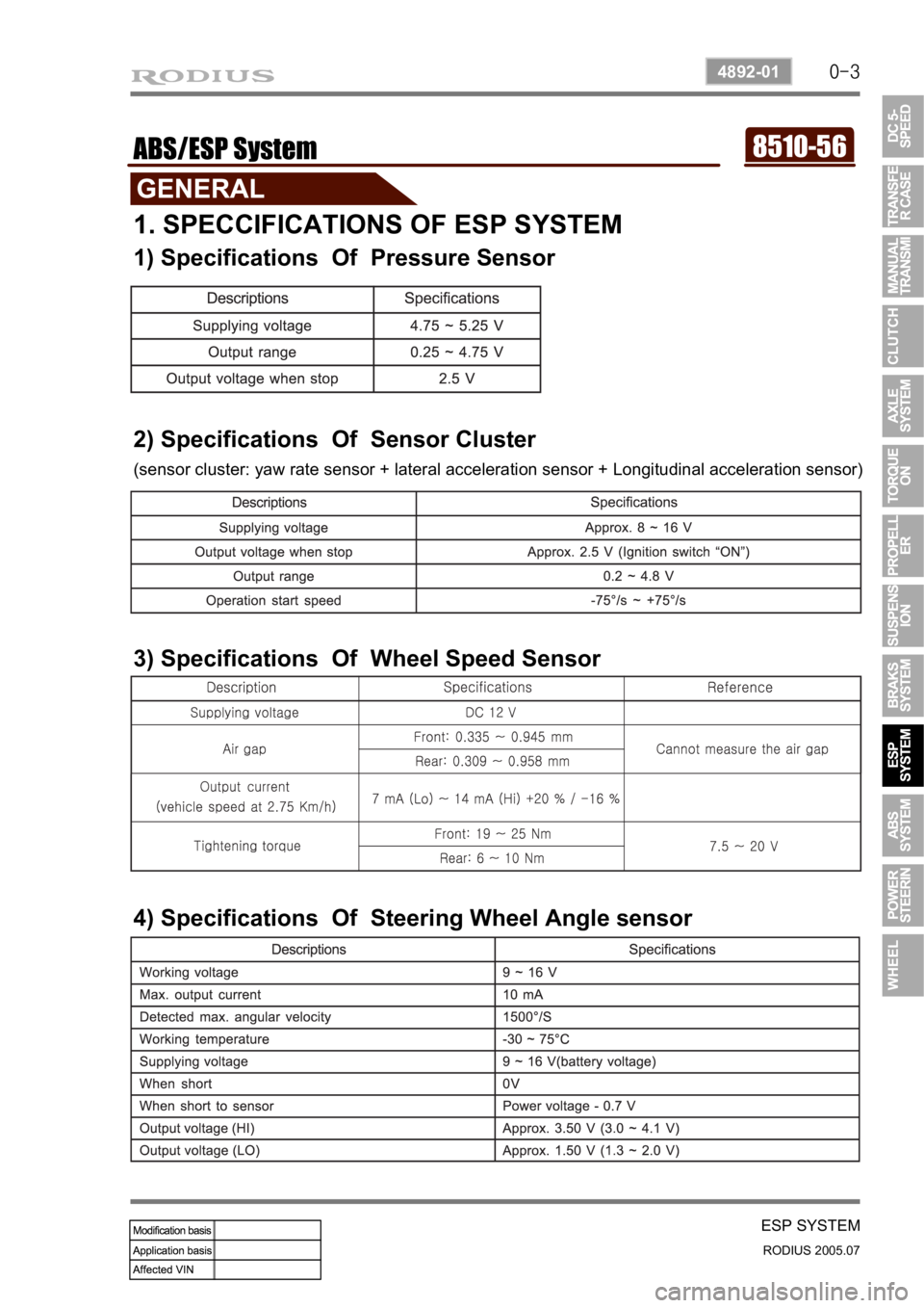
1. SPECCIFICATIONS OF ESP SYSTEM
1) Specifications Of Pressure Sensor
2) Specifications Of Sensor Cluster
(sensor cluster: yaw rate sensor + lateral acceleration sensor + Longitudinal acceleration sensor)
3) Specifications Of Wheel Speed Sensor
4) Specifications Of Steering Wheel Angle sensor
Page 237 of 502
0-4
RODIUS 2005.07
4892-01
ESP SYSTEM
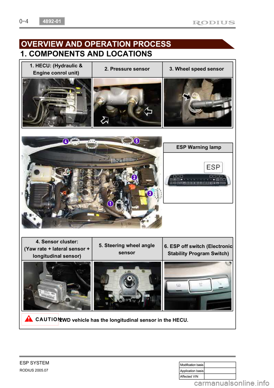
1. COMPONENTS AND LOCATIONS
2WD vehicle has the longitudinal sensor in the HECU.
1. HECU: (Hydraulic &
Engine conrol unit) 2. Pressure sensor 3. Wheel speed sensor
4. Sensor cluster:
(Yaw rate + lateral sensor + longitudinal sensor) 5. Steering wheel angle
sensor 6. ESP off switch (Electronic
Stability Program Switch) ESP Warning lamp
Page 239 of 502
0-6
RODIUS 2005.07
4892-01
ESP SYSTEM
3. ESP SYSTEM DESCRIPTION
1) Principle of ESP
ESP (Electronic Stability Program) recognizes critical driving conditions, such as panic
reactions in dangerous situations, and stabilizes the vehicle by wheel-individual braking and
engine control intervention with no need for actuating the brake. This system is developed to
help the driver avoid the danger of losing the control of the vehicle stability due to under-
steering or over-steering during cornering.
The yaw rate sensor, lateral sensor and longitudinal sensor in the sensor cluster and the
steering wheel angle sensor under the steering column detect the spin present at any wheels
during over-steering, under-steering or cornering. The ESP ECU controls against over-steering
or under-steering during cornering by controlling the vehicle stability using the input values from
the sensors and applying the brakes independently to the corresponding wheels.
The system also controls during cornering by detecting the moment right before the spin and
automatically limiting the engine output (coupled with the ASR system).
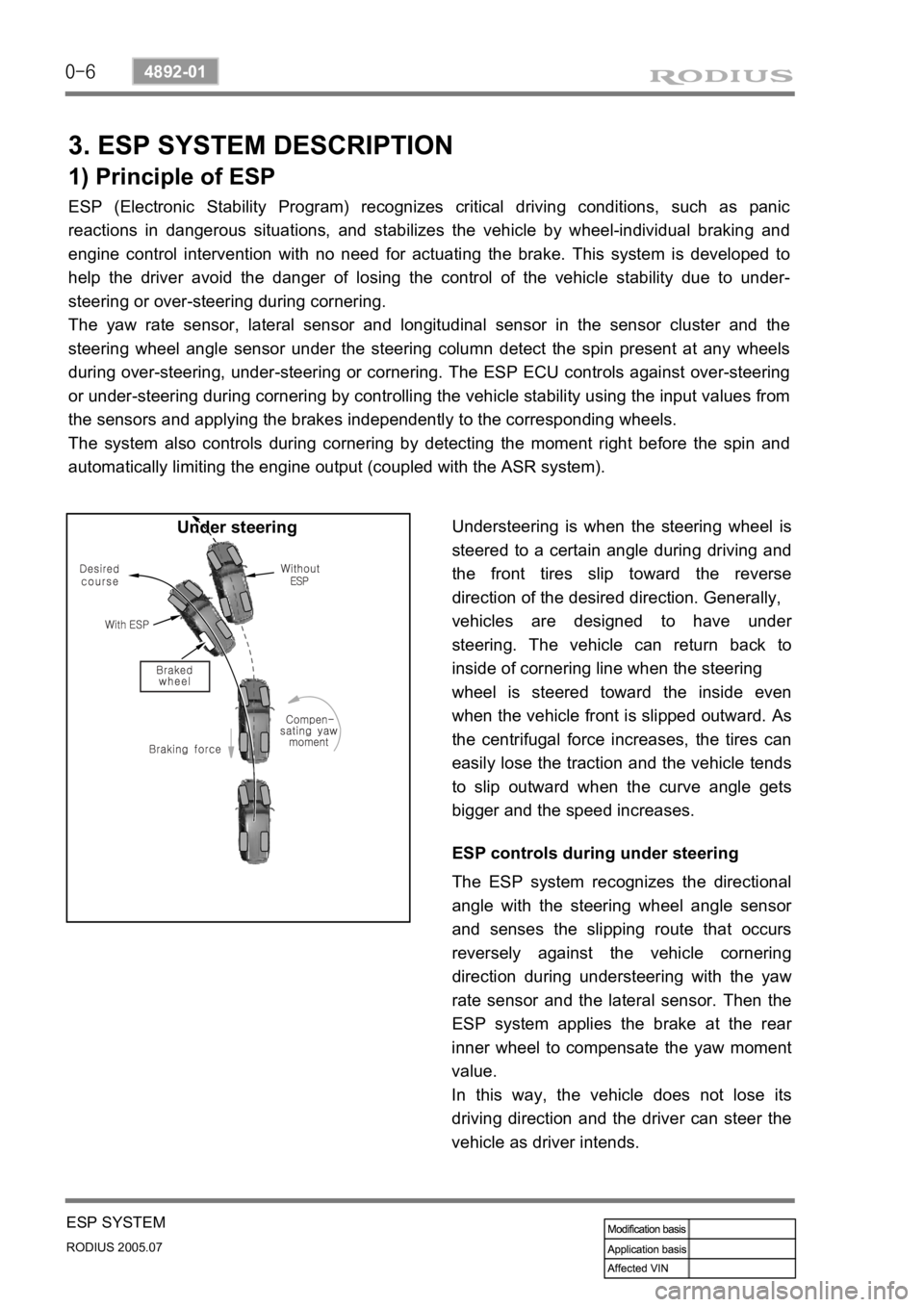
Understeering is when the steering wheel is
steered to a certain angle during driving and
the front tires slip toward the reverse
direction of the desired direction. Generally,
vehicles are designed to have unde
r
steering. The vehicle can return back to
inside of cornering line when the steering
wheel is steered toward the inside even
when the vehicle front is slipped outward.
As
the centrifugal force increases, the tires can
easily lose the traction and the vehicle tends
to slip outward when the curve angle gets
bigger and the speed increases. Under steering
ESP controls during under steering
The ESP system recognizes the directional
angle with the steering wheel angle senso
r
and senses the slipping route that occurs
reversely against the vehicle cornering
direction during understeering with the yaw
rate sensor and the lateral sensor. Then the
ESP system applies the brake at the rea
r
inner wheel to compensate the yaw moment
value.
In this way, the vehicle does not lose its
driving direction and the driver can steer the
vehicle as driver intends.
Page 240 of 502
0-7
ESP SYSTEM
RODIUS 2005.07
4892-01
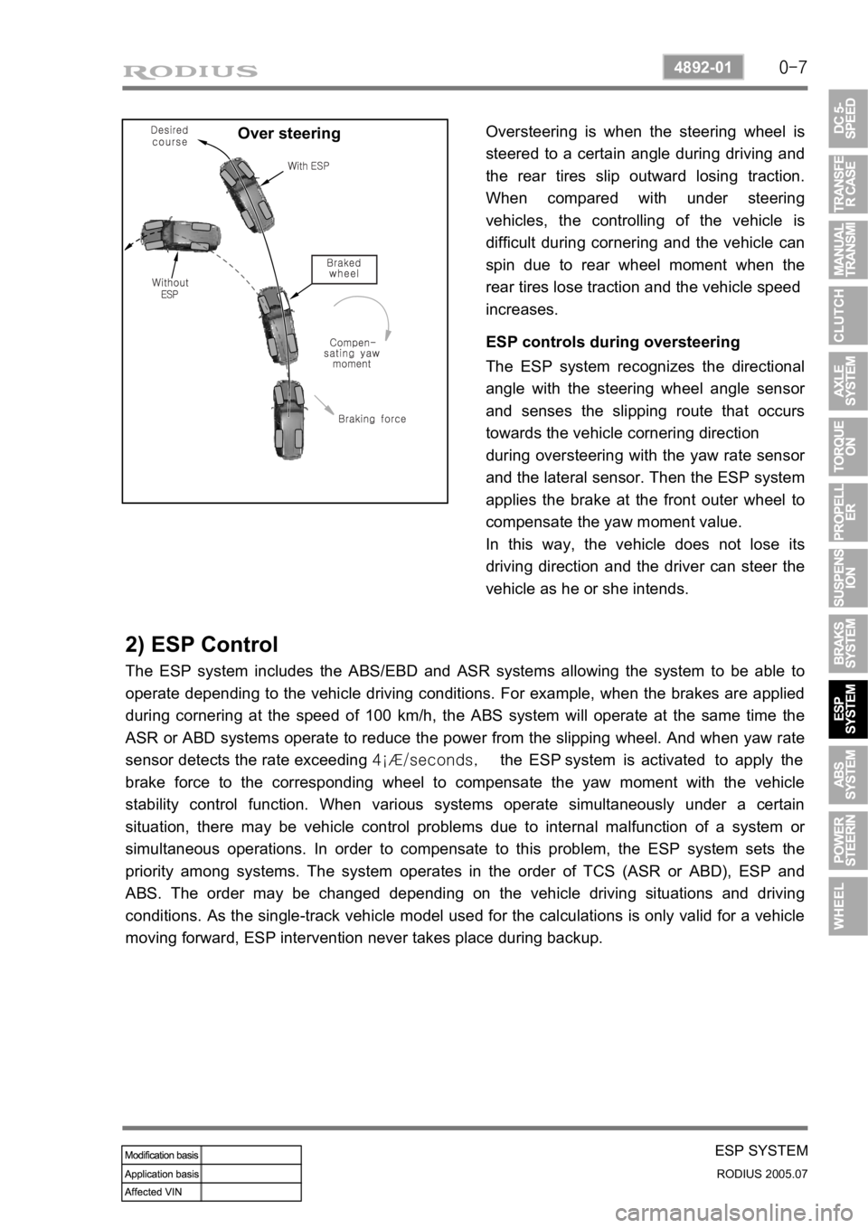
Over steeringOversteering is when the steering wheel is
steered to a certain angle during driving and
the rear tires slip outward losing traction.
When compared with under steering
vehicles, the controlling of the vehicle is
difficult during cornering and the vehicle can
spin due to rear wheel moment when the
rear tires lose traction and the vehicle speed
increases.
ESP controls during oversteering
The ESP system recognizes the directional
angle with the steering wheel angle senso
r
and senses the slipping route that occurs
towards the vehicle cornering direction
during oversteering with the yaw rate senso
r
and the lateral sensor. Then the ESP system
applies the brake at the front outer wheel to
compensate the yaw moment value.
In this way, the vehicle does not lose its
driving direction and the driver can steer the
vehicle as he or she intends.
2) ESP Control
The ESP system includes the ABS/EBD and ASR systems allowing the system to be able to
operate depending to the vehicle driving conditions. For example, when the brakes are applied
during cornering at the speed of 100 km/h, the ABS system will operate at the same time the
ASR or ABD systems operate to reduce the power from the slipping wheel. And when yaw rate
sensor detects the rate exceeding 4¡Æ/seconds, the ESP system is activated to apply the
brake force to the corresponding wheel to compensate the yaw moment with the vehicle
stability control function. When various systems operate simultaneously under a certain
situation, there may be vehicle control problems due to internal malfunction of a system o
r
simultaneous operations. In order to compensate to this problem, the ESP system sets the
priority among systems. The system operates in the order of TCS (ASR or ABD), ESP and
ABS. The order may be changed depending on the vehicle driving situations and driving
conditions. As the single-track vehicle model used for the calculations is only valid for a vehicle
moving forward, ESP intervention never takes place during backup.
Page 275 of 502

0-3
POWER STEERING SYSTEM
RODIUS 2005.07
4610-00
4610-00POWER STEERING SYSTEM
1. SPECIFICATION
Page 276 of 502

0-4
RODIUS 2005.07
4610-00
POWER STEERING SYSTEM
2. TIGHTENING TORQUE
3. SPECIAL TOOLS AND EQUIPMENT
Page 277 of 502
0-5
POWER STEERING SYSTEM
RODIUS 2005.07
4610-00
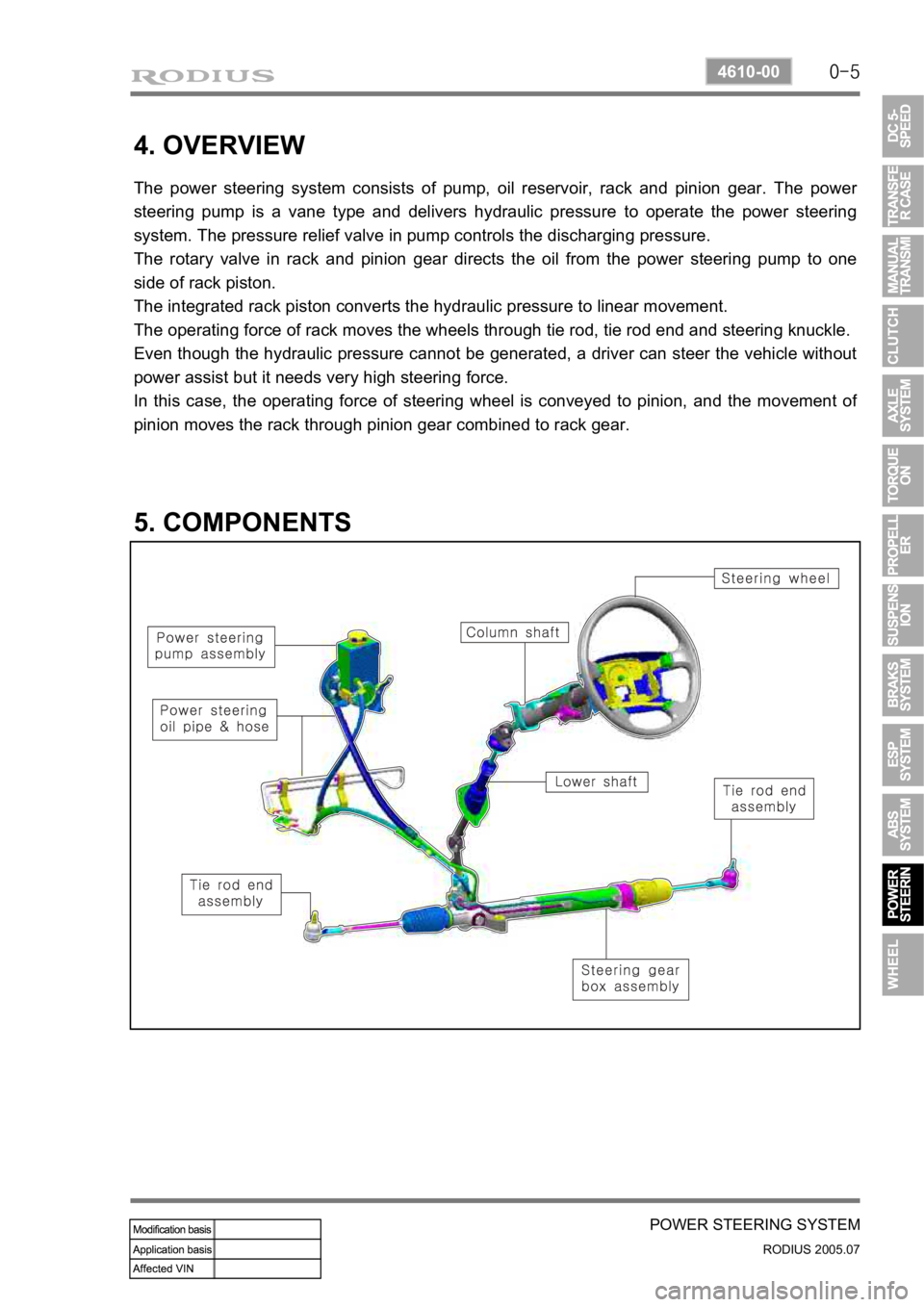
4. OVERVIEW
The power steering system consists of pump, oil reservoir, rack and pinion gear. The power
steering pump is a vane type and delivers hydraulic pressure to operate the power steering
system. The pressure relief valve in pump controls the discharging pressure.
The rotary valve in rack and pinion gear directs the oil from the power steering pump to one
side of rack piston.
The integrated rack piston converts the hydraulic pressure to linear movement.
The operating force of rack moves the wheels through tie rod, tie rod end and steering knuckle.
Even though the hydraulic pressure cannot be generated, a driver can steer the vehicle without
power assist but it needs very high steering force.
In this case, the operating force of steering wheel is conveyed to pinion, and the movement o
f
pinion moves the rack through pinion gear combined to rack gear.
5. COMPONENTS
Page 278 of 502

0-6
RODIUS 2005.07
4610-00
POWER STEERING SYSTEM
1. COMPONENTS OF POWER STEERING ASSEMBLY